
Abstract
The 0.1%C–5%Mn steel is a new type low carbon medium-manganese steel adapted to the requirements of auto light weight, good safety, low energy consumption and low manufacturing cost. Lots of thermal simulation experiments and macrostructure detections have been carried out to analyse solidification characteristics of this steel. The effect of composition of steel, casting process and slab section on solidified structure and the quality defects have been analysed. The results showed that there are interdendritic crack, centre segregation, porosity and shrinkage cavity in the internal of this steel. In order to improve internal quality of the ingot, small cross section ingot should be chosen preferentially to obtain small dense structure by increasing the cooling rate meanwhile the ingot stripped should be cooled slowly. The main casting measures for heavy section ingot should include reducing the degree of superheat and casting speed, slowing down the mould cooling intensity, prolonging the ingot upper cap time and using slow cooling mode.
Introduction
Reasonable lightweight of automobile is the key technology route to reduce fuel consumption and exhaust emissions, has become the main development direction of automobile industry in recent years. Therefore, the effective ways and means to reduce car weight is being sought actively in the global automotive industry aiming at developing environmentally friendly and safer cars. The researchers in steel industry is also take an active part in that development of materials with high strength, good plasticity, formability and weld properties through technological innovation in order to reduce the weight of automobile and improve the crash safety [1–4].
In October 2010, China launched the 973 project ‘basic research on organization control theory and technology of high performance steel’, which mainly focused on the development the third generation of automotive steel technology equal to the international advanced level. Developing the third generation of automotive steel with more than 30 GPa•% of tensile strength (>500 MPa) and total elongation (>20%) product has become a hot work in recent years [5–13] in order to achieve the goal of both lightweight and safety improvement in automobile industry. The 0.5%C–0.1%Mn steel is one of the third generation of automotive steel. Solidification characteristics have been researched using the method of thermal simulation experiment in this paper aiming at providing theoretical guidance for optimization of continuous casting industrial experiment.
Thermal simulation experiment research on solidification character of ingot
Thermal simulation experiment method and process
A large number of casting experiments were carried out using a 30 kg vacuum induction furnace with double function of solidification and casting, the process was: dosing, vacuum melting, casting, heating preservation of ingots, cutting and sampling of the ingot, structure analysis, and performance test.
The vacuum induction furnace includes medium frequency power supply and control system, water cooling system, temperature measuring and feeding and sampling system, vacuum system, heating electrode, furnace body, furnace cover, induction furnace and rotary casting system, liquid steel separator (nozzle), casting mould, etc.
The rated power of the vacuum induction furnace is 75 kW, the rated frequency is 2500 Hz, and the ultimate vacuum degree is 0.006 Pa. In the process of smelting, the pure iron bar is put into the induction furnace to melt, and the alloy elements are added after being melted. The temperature is measured, the vacuum is broken, and at last the casting is finished.
The molten steel is solidified by injection into a self-made water cooling mould through the liquid steel separator, and the water-cooled copper mould is equivalent to a continuous casting mould. The height of the mould is 230 mm, and the section and cooling mode of the ingot can be designed according to the experimental requirements. At the end of casting, the casting mould can be separated quickly to ensure that the casting ingot is removed at the required temperature. Some ingots which are put into the holding furnace have been cooled slowly when their surface temperature reaches 400°C or so.
Experimental scheme of die casting.
Notes: (1) The meaning of Air cooling is that ingots are cooled in the air after demoulding. (2) The meaning of slow cooling is that ingots are cooled put to the holding furnace.
Effect of casting process on microstructure of the solidified ingot
(1) Effect of superheat on solidification structure of ingot
Casting temperature in No. 2 and No. 3 furnace experiment is 1535°C and 1580°C, respectively while other processes are the same. Ingot solidification structure of the longitudinal cross section has been shown in Figure 1. Effect of casting temperature on solidification structure of ingot. (a) No.2 furnace experiment, casting temperature :1535°C, Air cooling,230mm(length)×110mm(thickness) (b) No.3 furnace experiment, casting temperature :1580°C, Air cooling,230mm(length)×110mm(thickness).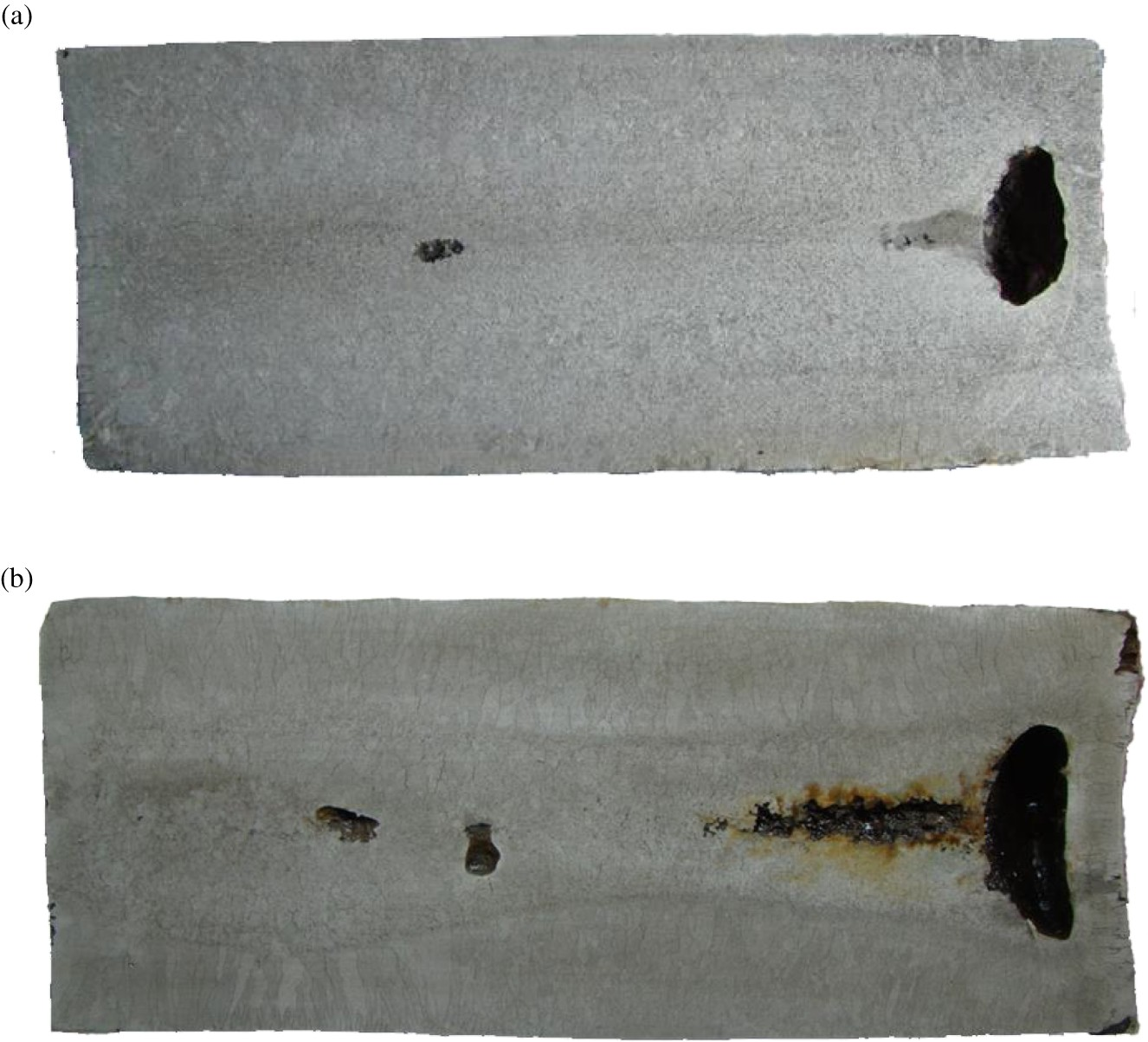
It can be seen that after superheat is increased, the internal shrinkage cavity and interdendritic crack are more serious, and the equiaxed grain ratio is lower. When casting temperature is 1535°C, the average equiaxed grain ratio of ingot is about 62%, and the equiaxed grain and columnar grain are both dense. When casting temperature is 1580°C, the average equiaxed grain ratio of ingot is about 45%, the equiaxed grain is dense while the columnar grain is bulky. The equiaxed grain zone is seemed as ‘vase’ shape from bottom to top of ingot. The bottom equiaxed grain zone is wider. (2) Effect of section size on solidification structure of ingot
Thickness of ingot in No. 6.8 furnace experiment is 110 mm and 50 mm, respectively while other processes are similar. Ingot solidification structure of the longitudinal cross section has been shown in Figure 2. Effect of section size on solidification structure of ingot. (a) No.6 furnace experiment, casting temperature :1567°C, 400°C slow cooling,230mm(length)×110mm(thickness) (b) No.8 furnace experiment, casting temperature :1560°C, 350°C slow cooling,230mm(length)×50mm(thickness).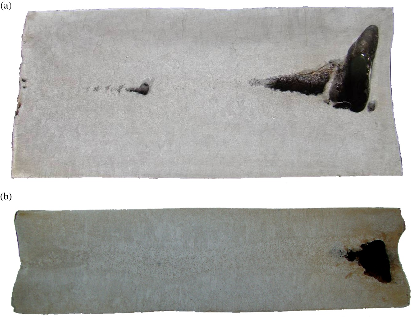
It can be seen that after the thickness of ingot decreases from 110 to 50 mm, under the condition of slow cooling, the crack between dendrites and the central shrinkage cavity is alleviated. Although the proportion of the central equiaxed zone is slightly decreased, the equiaxed and columnar microstructure is more dense, especially the columnar microstructure has been refined and densified. (3) Effect of cooling method on solidification structure of ingot
Compared with the No. 6 experiment (Figure 2(a)), the No. 5 experiment changed the cooling mode of the casting mould. During the solidification process, insulating refractory material was embedded in the upper part of the water-cooled mould. In this case, the solidification rate of molten steel on the upper part of the casting mould is greatly reduced. The No. 5 experiment ingot solidification structure of the longitudinal cross section is shown in Figure 3. The casting temperature is 1565°C and the casting speed is slow (about 1.0 m/min). The ingot which has been put into the holding furnace have been cooled slowly when the surface temperature reaches 400°C or so. It can be seen from Figure 3 that the central shrinkage cavity of ingot was improved and the crack between dendrites was reduced using this casting process. The width and number of cracks are reduced by more than one time. The longitudinal section solidification structure of No. 5 furnace experimental ingot with slow cooling mould.
Compared with No. 3 experiment (Figure 1(b)), the No. 4 experiment changed the cooling mode of the demoulding ingot from ‘direct air cooling’ to ‘400°C temperature holding furnace slow cooling to room temperature’. The No. 4 experiment ingot solidification structure of the longitudinal cross section is shown in Figure 4. The casting temperature is 1580°C and the casting speed is high (about 1.5 m/min). It can be seen that although the ingot is cooled slowly by the holding furnace, the cracks between dendrites and the central shrinkage cavity are not alleviated, which is related to the high casting temperature and speed. The longitudinal section solidification structure of No. 4 furnace experimental ingot with slow cooling and heat preservation.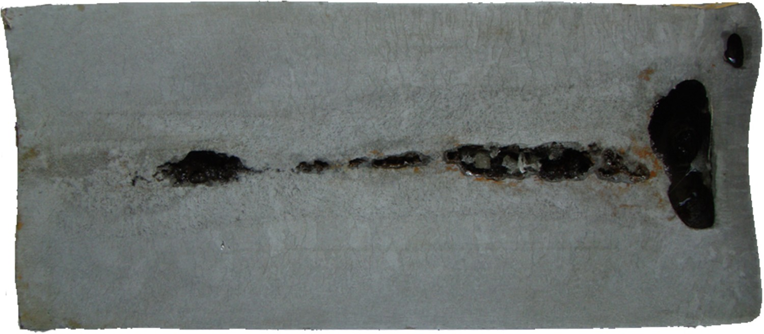
Compared with No. 8 experiment (Figure 2(b)), the No. 7 experiment changed the cooling mode of the demoulding ingot from ‘holding furnace slow cooling’ to ‘direct air cooling’. The No. 7 experiment ingot solidification structure of the longitudinal cross section is shown in Figure 5. The casting temperature is 1560°C and the casting speed is lower. It can be seen that the cracks between dendrites and the central shrinkage cavity are more serious. The longitudinal section solidification structure of No. 7 furnace experimental 50 mm thick ingot with air cooling.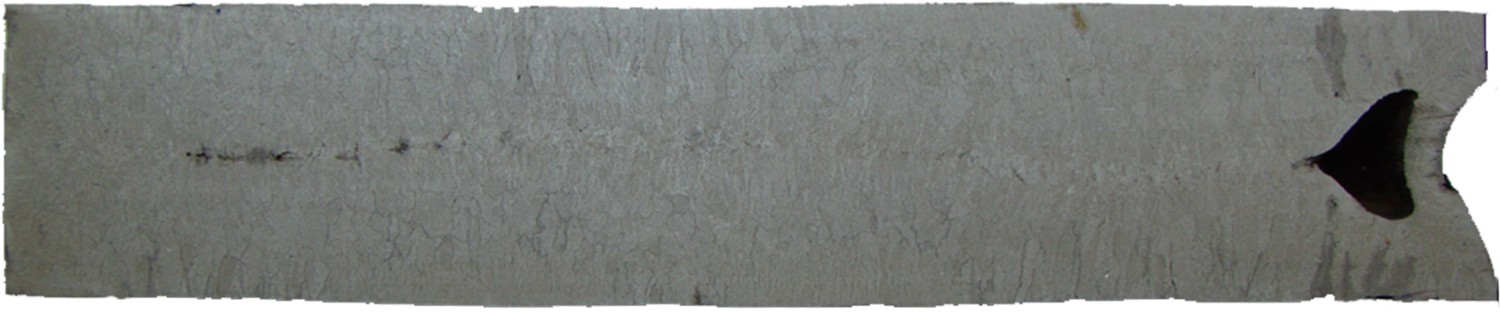
It can be seen from the above comparative analysis of solidification structure that, in order to reduce the central shrinkage and crack, the casting of ingot with small section can be firstly selected to obtain small and dense structure. Meanwhile, the casting ingot should be put into holding furnace to be cooled slowly after demoulding. Comprehensive experimental results show that the main casting measures for heavy section ingot should include reducing the degree of superheat and casting speed, slowing down the mould cooling intensity, prolonging the ingot upper cap time and using slow cooling mode for demoulding ingot.
Microstructure characteristics of ingot dendrite
For the cross section 100 mm×110 mm and 100 mm×50 mm ingot, solidification microstructure at different distances from the surface are shown in Figures 6 and 7, respectively. Solidification microstructure of 100 mm×110 mm ingot. (a) 10 mm away from the surface (b) 20mm away from the surface (c) 30 mm away from the surface (d) 40 mm away from the surface. Solidification microstructure of 100 mm×50 mm ingot. (a) 10mm away from the surface (b) 20mm away from the surface (c) 25 mm away from the surface.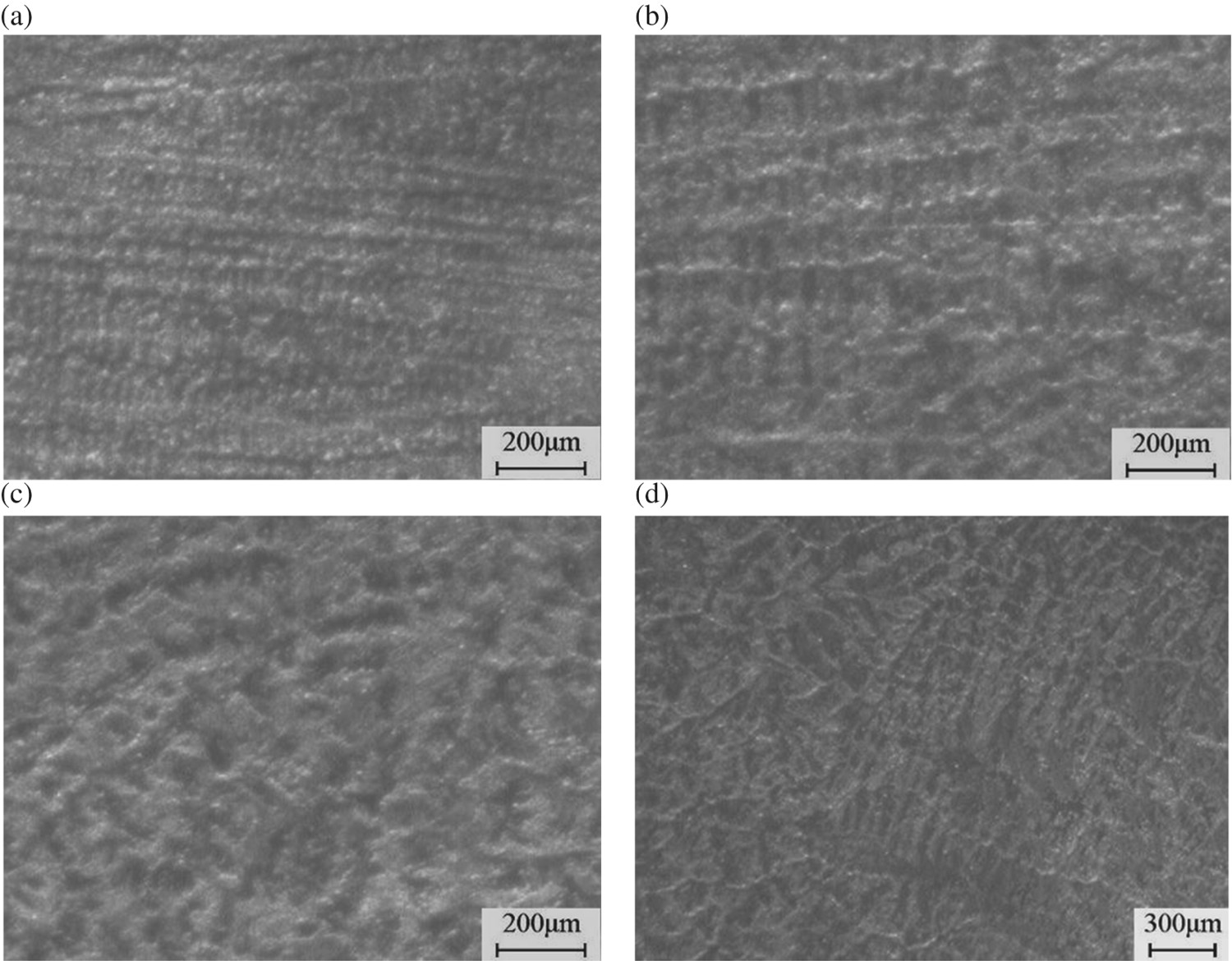
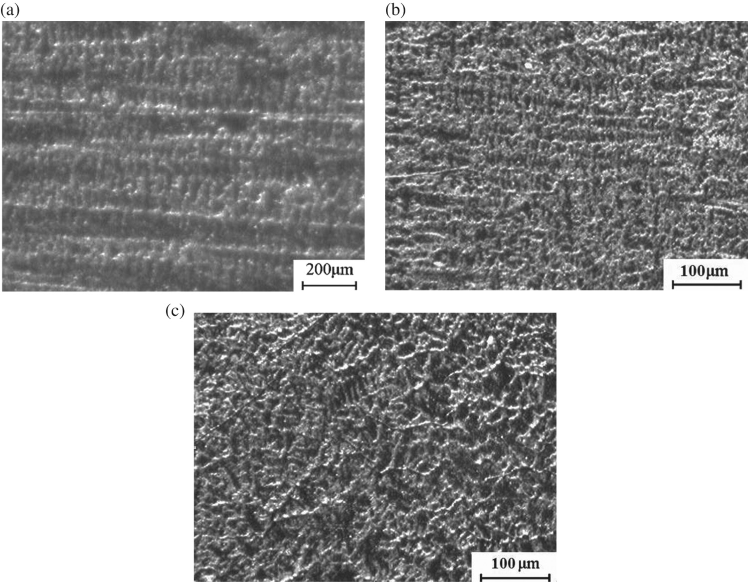
The results show that the ingot is composed of fine equiaxed grains, dendrites and coarse equiaxed grains from surface to core. It can be seen from Figures 6 and 7 that for ingots with a section of 100 mm×110 mm, the growth orientation of dendrites begins to be disordered at 30 mm from the surface (core is 55 mm from the surface) where CET takes place. For ingots with a section of 100 mm×50 mm, CET takes place at 20 mm from the surface (core is 25 mm from the surface). It can be seen that CET takes place much earlier for small cross-sectional ingots because of its higher columnar crystal ratio. The above studies on CET has important reference significance for developing solidification structure control technology.
Solidification structure characteristics of slab and ingot
In order to investigate the feasibility of producing 0.1%C–5%Mn steel by continuous casting process and study the quality of slab, the first industrial production test has been carried out at TISCO, in Taiyuan, China. The section of continuous casting slab is 220 mm×1260 mm, and the casting speed is 0.85 m/min. After casting, the slab is put into a annealing furnace for slow cooling.
Solidification structure characteristics of slab
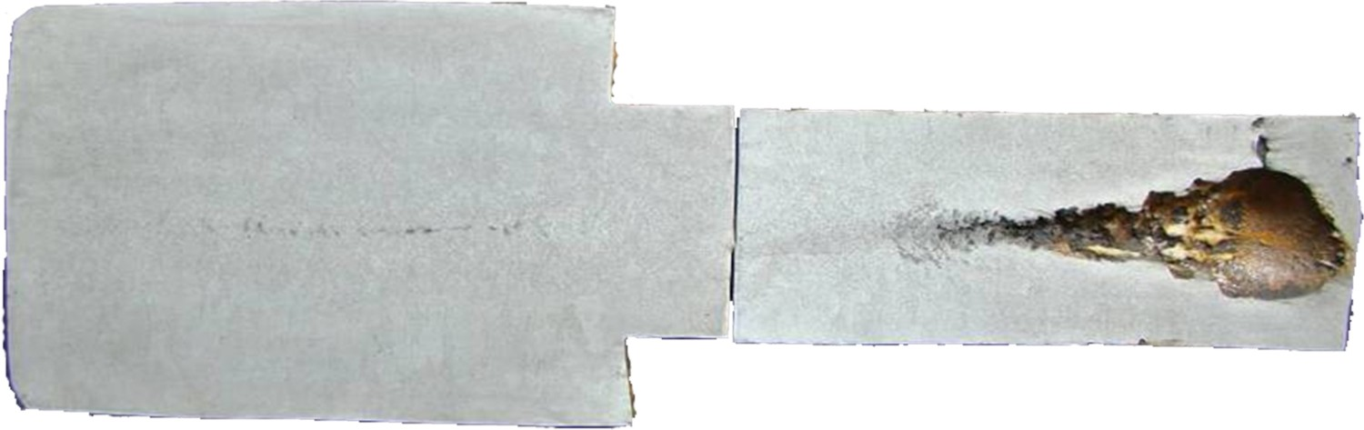
After slab was taken out from the annealing furnace, the transverse and longitudinal samples of slab were intercepted by means of artificial flame cutting, as shown in Figure 8. Slab sampling method.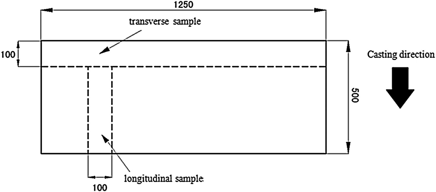
In order to the solidification macrostructure of slab has been analysed by heat etching test using HCl solution whose temperature is 70∼80°C and concentration is 50%. The dendritic microstructure of slab has been analysed by etching test using HNO3 solution.
Figures 9 and 10 show the solidification structure of the cross section and longitudinal section of the slab produced by industrial test, in which the thickness of the slab is 220 mm. The results of field sulphur print analysis show that the central segregation and porosity of the slab are serious, and the grade reaches 2.0. Solidification structure of slab cross section (outside-in oriented casting direction). (a) Side macrostructure (b) Central macrostructure. Solidification structure of slab with longitudinal section.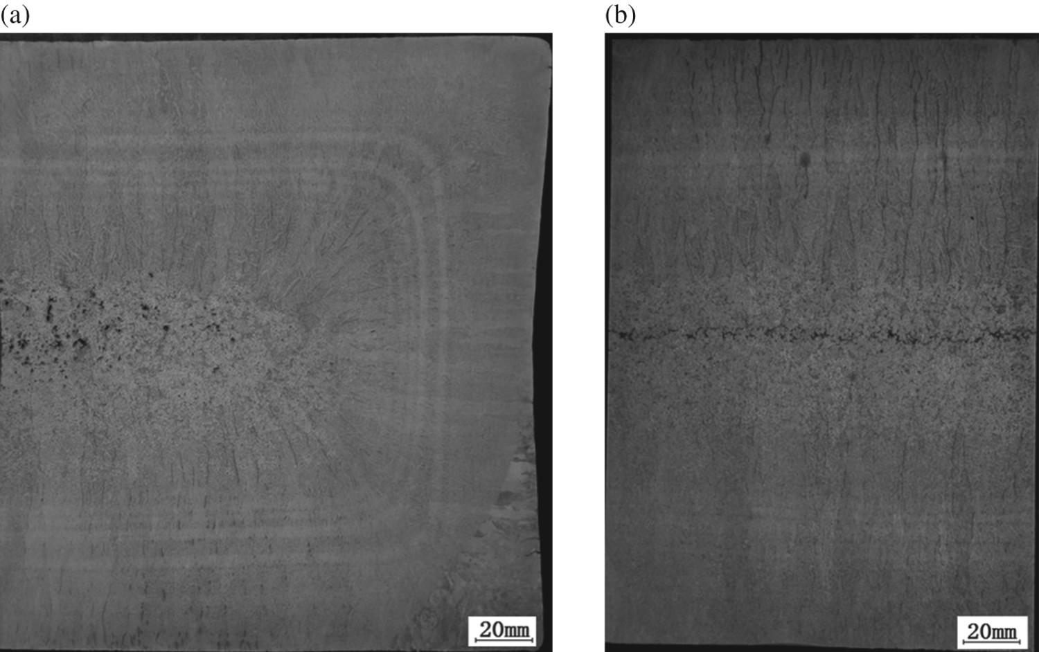
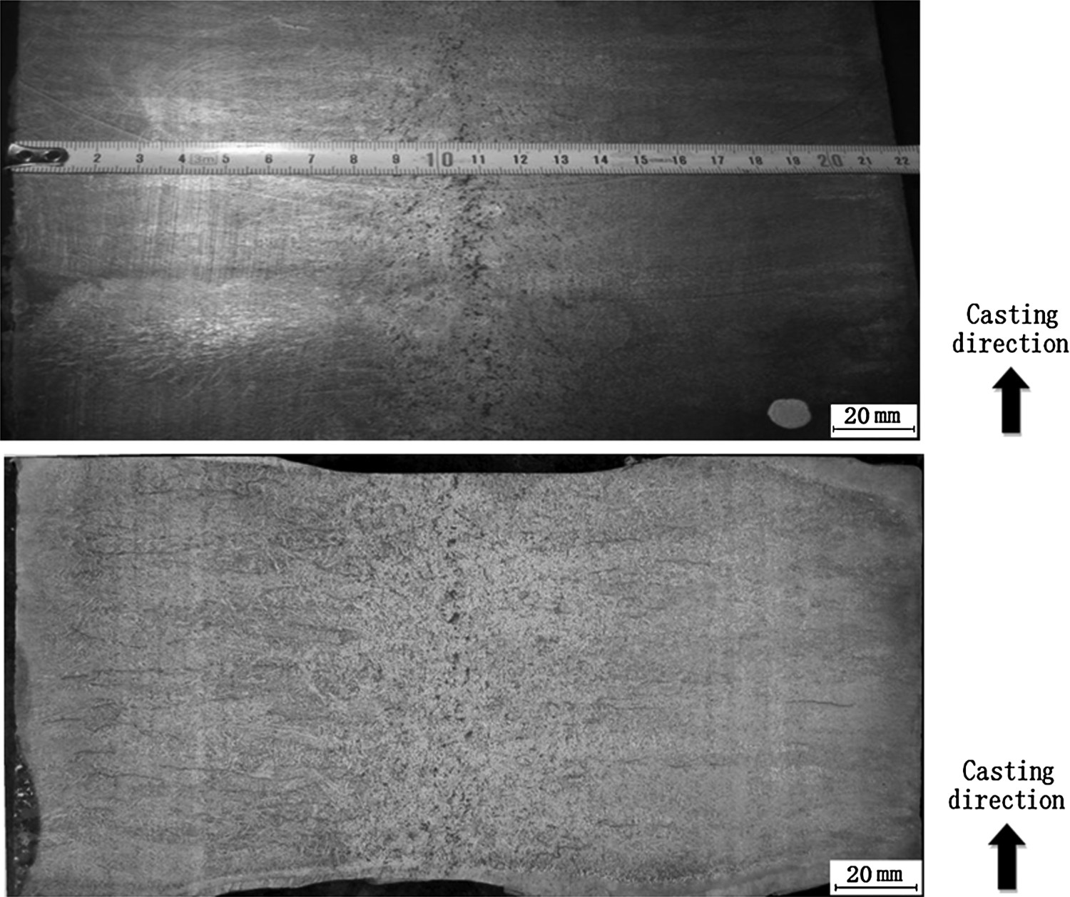
It can be seen that the solidification structure from the surface to the centre of slab is in turn chilling layer, columnar grain zone and central equiaxed grain zone.
According to the side cross-section structure shown in Figure 9(a), dendritic structure is dense and there are only a little cracks in corner and right side area. After the surface distance is about 100 mm away from the corner, interdendritic microcracks appear in columnar grain zone from outside to inside. A large number of shrinkage cavity appear in the equiaxed zone, with the maximum diameter of shrinkage cavity up to 5 mm. The proportion of equiaxed grain in thickness is about 24%.
According to the central cross-section structure shown in Figure 9(b), first of all, the boundary between columnar grain and equiaxed grain is clear, and there is no obvious columnar crystal disorder zone or CET transition zone. Second, there are a large number of cracks in the same direction as the columnar grain, and most of them are near the inner arc area. Some of the cracks penetrate through the chilling layer surface,and some extend throughout the entire columnar grain and even into the central equiaxed zone. Third, there is centreline segregation in the geometric centre of slab. The centre line of the isometric zone deviates from the geometric centre, close to the outer arc side. In the end, the crystal in central equiaxed grain zone is relatively dense. The proportion of equiaxed grain in thickness is also 24%.
According to the longitudinal section structure shown in Figure 10, segregation exists not only in the geometric centre line of the slab, but also in the central equiaxed grain region. The other characteristics of the longitudinal section structure are similar to the cross-section structure.
Figure 11 shows the dendritic microstructure of the industrial test slab from the surface to the centre. Solidification microstructure of slab at different distance from surface. (a) surface (b) 10mm away from the surface (c) 25mm away from the surface (d) 50mm away from the surface (e) 60mm away from the surface (f) 70mm away from the surface (g) 75mm away from the surface (h) 80mm away from the surface (i) 90mm away from the surface (j) 105mm away from the surface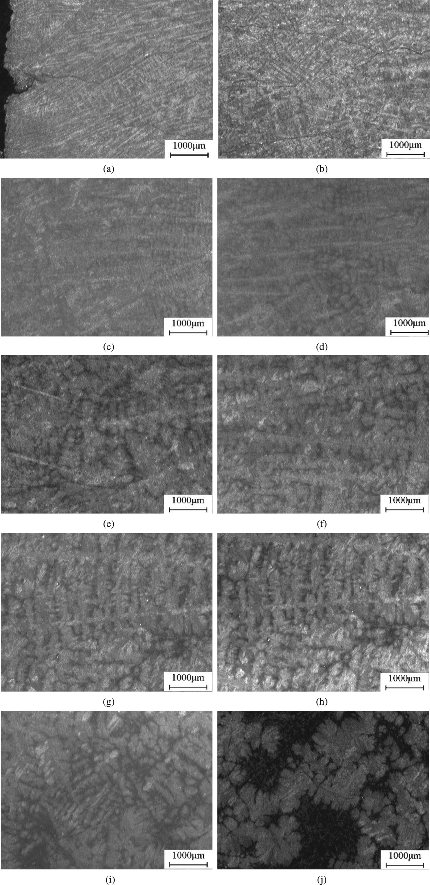
It can be seen that the dendrite crystals of the chilling layer on the surface of the cast slab are very fine and have no obvious orientation. In the slab thickness direction from the outside to inside, with the increase of distance from the surface, the dendrite size keeps growing, dendrite growth is consistent with the solidification direction gradually. When the distance from the surface of slab is 90 mm, the dendrite is no longer oriented, and the size of the dendrite is obviously different. The morphology is similar to that of the dendrite molten in the columnar grain region, indicating that the region from 80 to 90 mm away from the surface is the CET transition region.
When the distance from the slab surface is 105 mm, namely in the central regions of the slab, the dendrites are completely out of orientation, their sizes are almost uniform in all directions, appear as the equiaxed dendrites grain. Compared with dendrites in columnar grain area, the length of primary dendrite arm in central area is smaller obviously.
Dendrite spacing and cooling rate in ingot and slab
According to Figures 6, 7 and 11, the second dendrite spacing can be detected at different distances from the surface using a high magnification microscope.
Won and Thomas [14] summarized a large number of literature data. In view of the relationship between secondary dendrite spacing and cooling rate of steel, a widely used relational expression was obtained as follows:
λSDAS = (169.1−720.9C 0)CR − 0.4935 while 0 < [%C] ≤ 0.15 (1)
λSDAS = 143.9CR −0.3616 C 0 (0.5501−1.9996C 0) while [%C]>0.15 (2)
where λSDAS is secondary dendritic arm spacing (μm); C 0 is initial carbon content in steel (%); CR is cooling rate (°C/s).
Secondary dendrite spacing and cooling rate at different distances from the surface.
Macrosegregation of ingot and slab
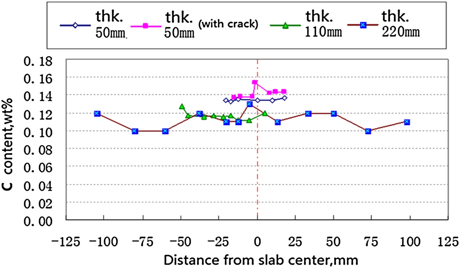
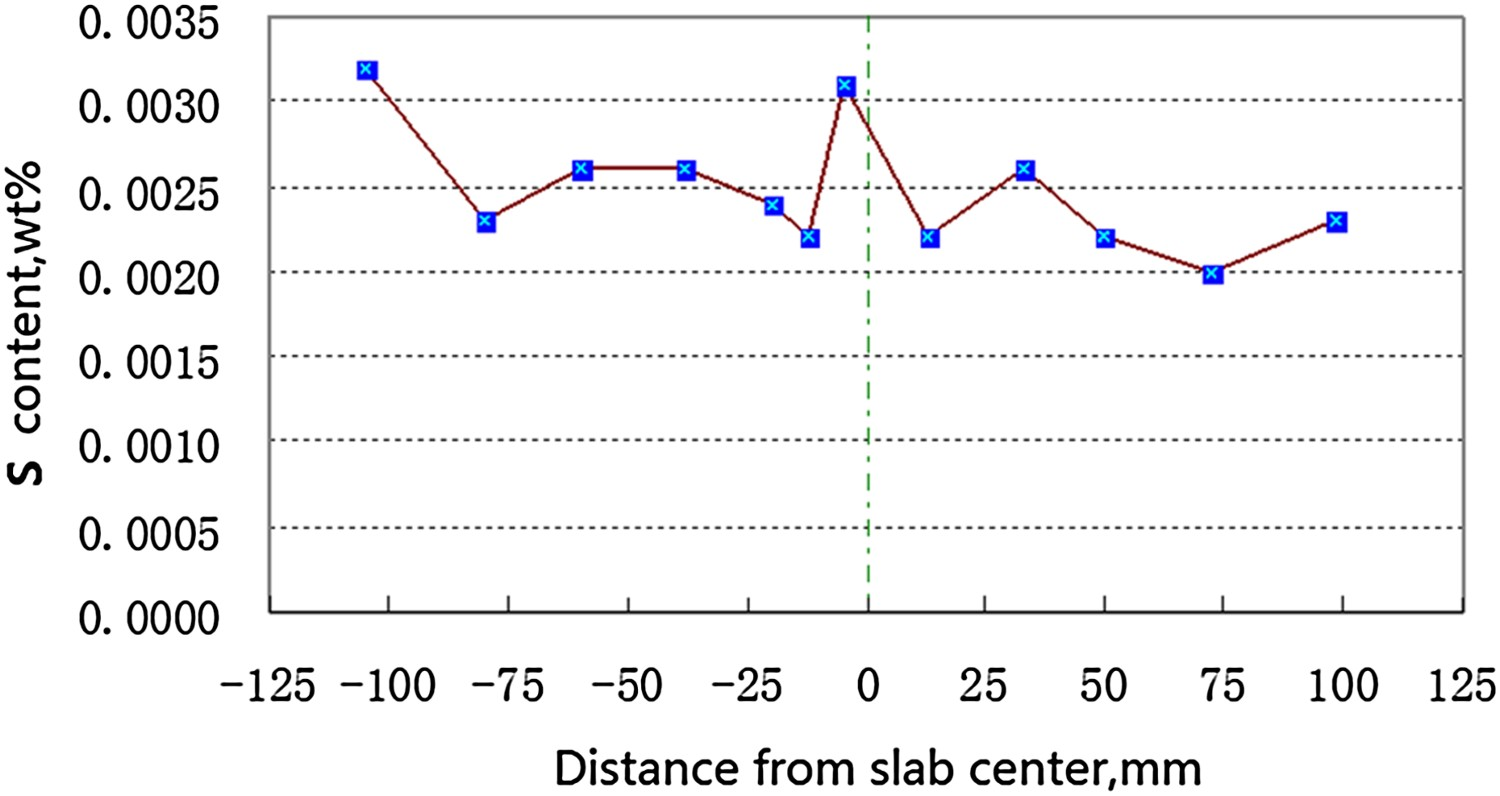
The compositions of ingot with a thickness of 50 and 110 mm produced in laboratory experiment and slab with a thickness of 220 mm produced in industrial test have been analysed. The composition changes of Mn, C and S elements in the thickness direction are detected by direct reading spectroscopy. The results are shown in Figures 12–14. Distribution of Mn elements in different section ingot in thickness direction. Distribution of C elements in different section ingot in thickness direction. Distribution of S elements in thickness direction of industrial continuous casting slab.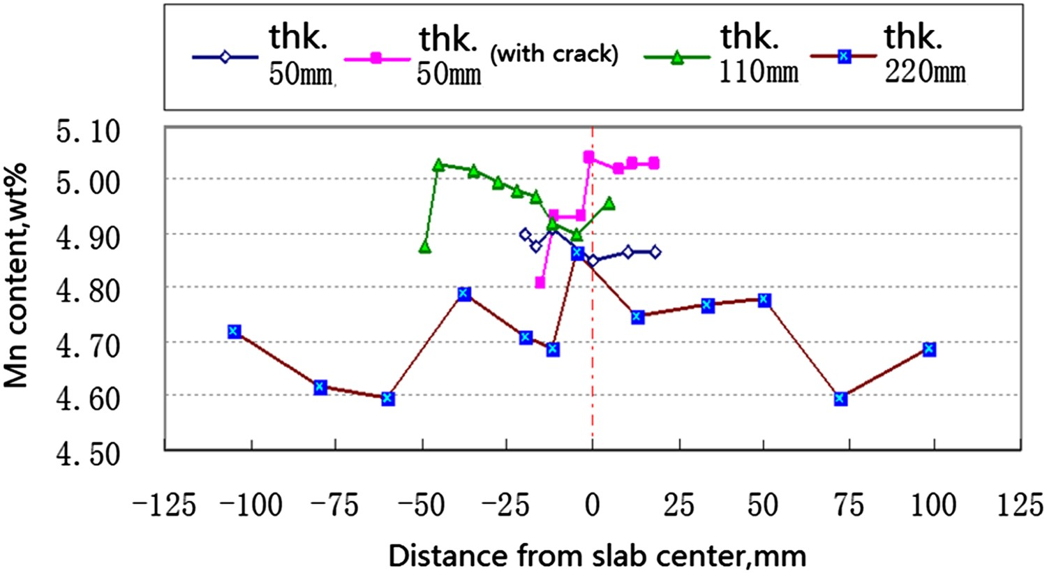
As can be seen from Figure 12, for ingot with a thickness of 50 mm, there is no obvious symmetrical distribution of Mn content in the thickness direction, while for industrial continuous casting slab, there is a symmetrical distribution of compositions. The content of Mn in the central area and at 50 mm away from the surface of slab is 4.87% and 4.60%, respectively.
It can be seen from Figure 13 that there is a symmetrical distribution of C content. For the industrial continuous casting slab, the content of C is in the central area and at 50 mm away from the surface of slab is 0.13% and 0.10%, respectively.
As can be seen from Figure 14, the S content is about 0.0031% at 5 mm away from surface and central area and 0.0020% at 182 mm away from surface.
Maximum segregation of Mn, C and S elements for different section castings in thickness direction.
Typical quality defects of ingot and slab
Centre segregation, looseness and shrinkage cavity
Upper shrinkage cavity of ingot
The heat simulation experiment of solidification structure of ingot shows that even if the upper part of mould has been embedded heat resistant refractory to reinforce shrinkage of steel, large shrinkage cavity will inevitably occur in the middle of the upper part of the ingot. The overall structure of the longitudinal section of the ingot is shown in Figure 15. It is very difficult to eliminate the upper shrinkage cavity of ingot. In the industrial production of die casting, the solution to the upper shrinkage cavity is to add the heating agent and thermal insulation material to the steel liquid surface quickly, and extend the sealing time of the upper ingot. Central segregation The longitudinal section of the centre of the ingot cast with the upper part of the mould with heat insulation refractory material.
The central segregation of continuous casting slab is more serious than that of laboratory ingot, in which the maximum segregation of C and S elements is 1.16 and 1.29, respectively, while the macroscopic segregation of Mn elements in ingot and slab is not obvious, and the maximum segregation of Mn elements in industrial slab is only 1.03. Central porosity and shrinkage cavity
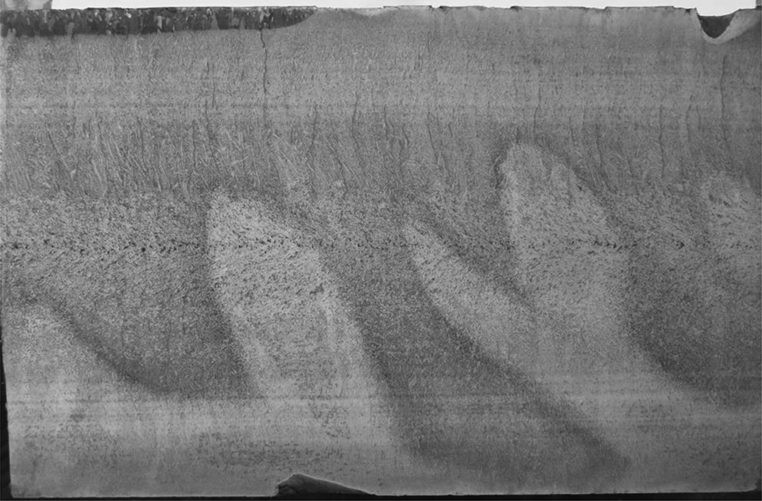
For ingot with a thickness of 110 mm and slab with a thickness of 220 mm, a certain number of porosity and shrinkage cavity defects exist in the central region. The central portion of slab is dominated by scattered porosity and the shrinkage cavity in ingot is more concentrated. The typical solidified structure at cross section of ingot is shown in Figure 16. Solidification structure at cross section of ingot with thickness of 110 mm.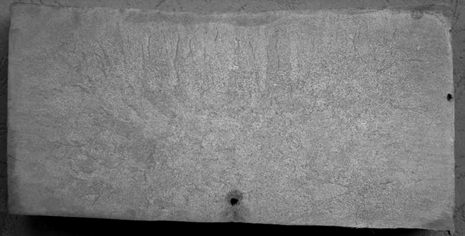
Interdendritic crack
Large number of microcrack defects exist between that solidified structure dendrites of the ingot and slab, and the typical cracks are shown in Figures 17 and 18. Crack morphology of cross section of ingot with thickness of 110 mm. Crack morphology of cross section of slab with thickness of 220 mm.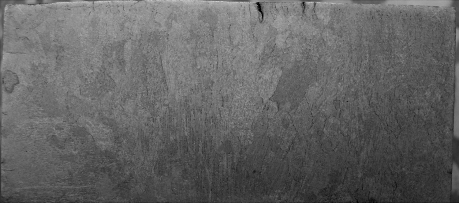
As can be seen from Figures 17 and 18, the main characteristics of internal interdendritic cracks are as follows: (1) The cracks are mainly distributed in the columnar grain region, and the equiaxial crystal region is mainly composed of segregation and shrinkage cavity defects. (2) The crack is very small, different in length, and a small number of microcracks appear through the surface. (3) The direction of the crack is roughly perpendicular to the surface. (4) The interdendritic cracks in the slab appear mostly in the inner arc zone.
Conclusion
The effect of casting process on solidification structure of ingot has been studied by casting test, and the characteristics of solidification structure of ingot and slab are analysed and the typical quality defects are clarified. The main results are as follows: In order to improve internal quality of the ingot, the cooling rate may be increased to obtain small dense structure for the small cross-section ingot meanwhile the ingot stripped should be cooled slowly. The main casting measures for heavy section ingot should include reducing the degree of superheat and casting speed, slowing down the mould cooling intensity, prolonging the ingot upper cap time and using slow cooling mode for solidified ingot. Compared with ingots, the segregation degree of continuous casting slab is relatively higher, and the main elements of the macrosegregation of slab are C and S, and their maximum segregation degree is 1.16 and 1.29, respectively, while the macrosegregation of Mn is not serious, and the maximum segregation degree of manganese in the slab is 1.03. The internal cracks are mainly distributed in the columnar grain region which is very small, different in length. The direction of the crack is roughly perpendicular to the surface. The interdendritic cracks in the slab appear mostly in the inner arc zone. For ingots with a section of 100 mm×110 mm, the growth orientation of dendrites begins to be disordered at 30 mm from the surface where CET takes place. For ingots with a section of 100 mm×50 mm, CET takes place at 20 mm from the surface.
Footnotes
Disclosure statement
No potential conflict of interest was reported by the authors.