
Abstract
Roll neck fracture was the result of the rotational-bending fatigue due to uncontrolled decreasing of the inlet rolling temperature. Three groups of design modifications of the roll neck have been considered to decrease maximum local stresses and to increase roll service life. In order to reduce energy consumption, influence of three different inlet rolling temperatures has also been considered. The negative influence of rolling temperature decreasing on roll fatigue life can be completely compensated by the adequate shape of roll neck and in that way reduce energy consumption and overall costs.
Introduction
For rolling mill rolls, flat or with grooves, the shoulder between roll necks is the most critical area on the rotational-bending fatigue due to stress concentration. For the rolls with grooves, the grooves can also be critical areas mostly depending on their shape [1]. Rolling force and rolling torque intensity depend on technological parameters. One of them is the temperature of the rolling material. The first part of this paper deals with one fracture of the roll neck during the rolling with stocks not warmed enough due to uncontrolled decreasing of the rolling stock inlet temperature. Based on the analysed fracture in the first part, three groups of design modifications of the roll neck have been considered to decrease maximum local stresses and to increase roll service life. Also, in order to reduce energy consumption, influences of three different inlet rolling temperatures were also considered.
Roll neck fracture
Rolls with grooves 3-roughing mill stand were fractured four times at the roll barrel [1] and two times at the roll neck (Figure 1). Regular service life of the roll is estimated on 16000 rolling tons of production (3 times machining due to wearing). The upper roll was in operation 4000 rolling tons, machined by a turning machine due to wearing and broke after 72 hours of operation after machining. In total, the roll fractured after 5000 rolling tons of production. Roll neck failures on 3-roughing mill stand. (a) Upper roll, (b) middle roll.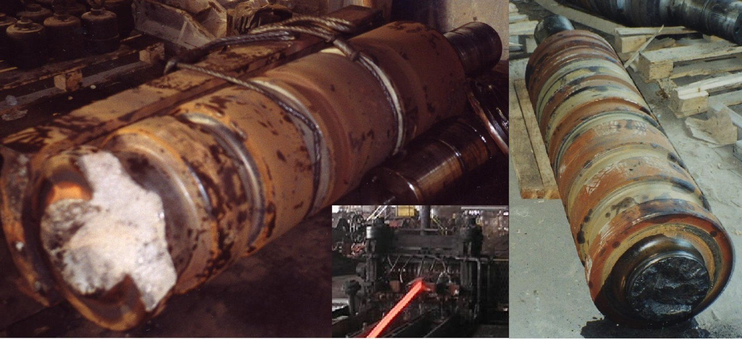
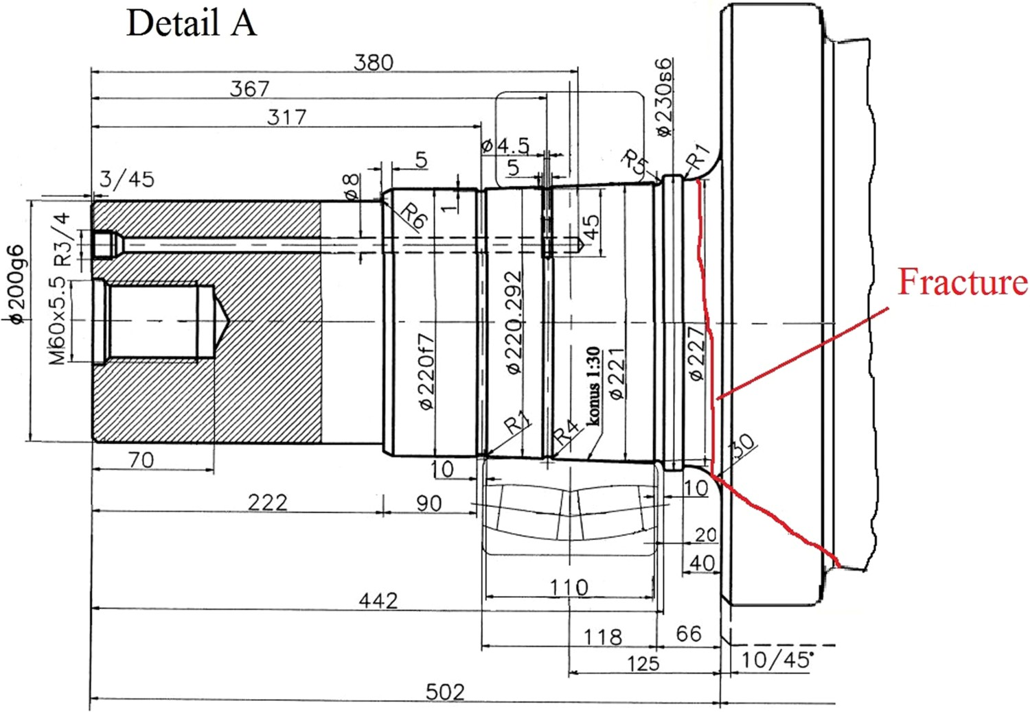
The fracture started on the fillet at the change between two different diameters of the roll approximately 30 mm from the bearing and spread through the roll barrel till the corner of the first groove (Figures 2 and 3). Upper roll with position of rolling stock at the time of the fracture. Roll neck with fracture position.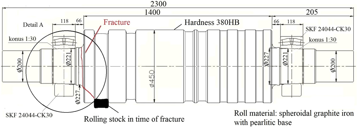
Fracture investigation
The chemical composition of the material was checked by quantimeter. The hardness testing and the microstructure confirmed that material of the roll was spheroidal graphite iron with the pearlitic base. The fracture surface was divided into three fracture regions (Figure 4); Region A – a region around the outer perimeter with multiple crack origins separated by ratchet marks; Region B – a region of the crack propagation zone in the middle; and Region C – a region of the final, fast fracture. Fracture surface.
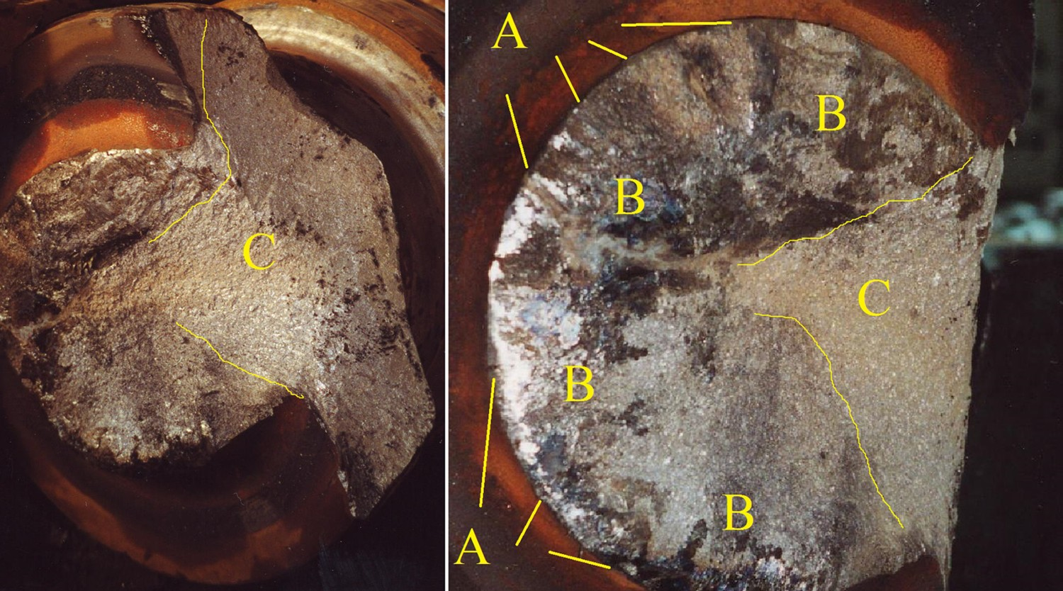
The cracks propagated circumferentially around the roll neck. The final fracture was a brittle fracture from the middle of the roll to the corner of the first groove (at C). The appearance of the fracture surfaces suggested that the roll fractured as a result of rotational-bending fatigue with a high stress concentration.
Roll stress analysis
Initial rolling stock was a billet with cross-section 100 mm square and 3 m initial length. During rolling in 3-roughing mill, the rolling stock had to pass through 10 passes; 8 passes in the first stand and 2 passes in the second stand following the rolling sequence (Figure 5). Rolling in 3-roughing mill stand.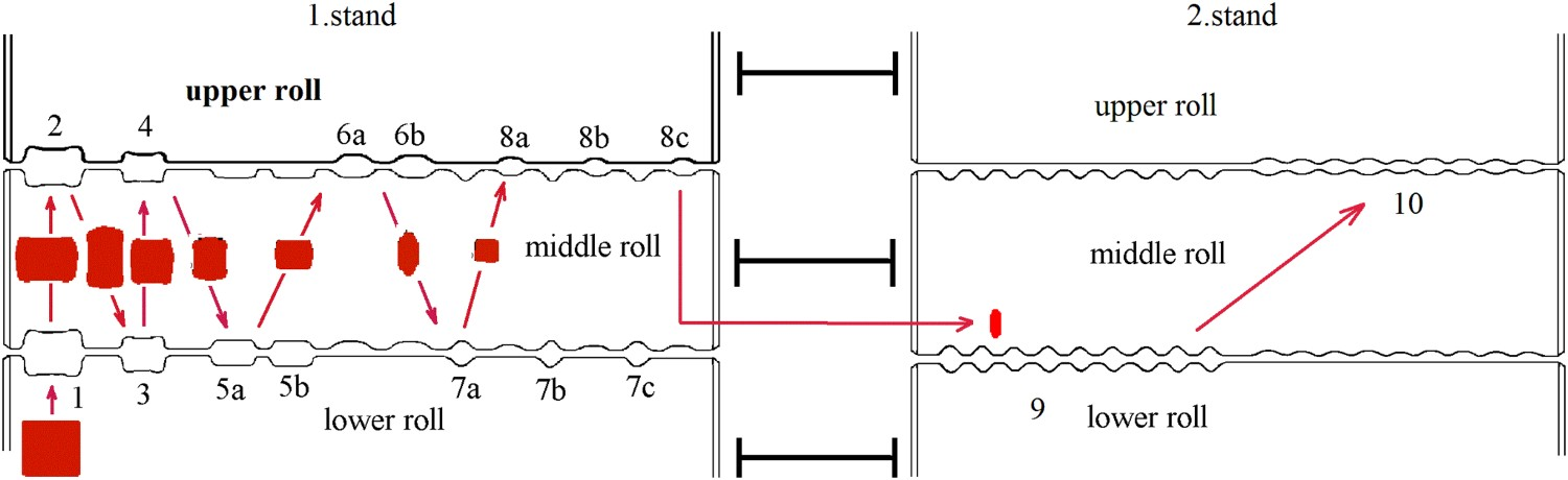
The lower and the middle rolls of the first stand were loaded during rolling in passes 1, 3, 5 and 7 and the middle and the upper rolls were loaded during rolling in passes 2, 4, 6 and 8. The lower and the middle rolls of the second stand were loaded during rolling in pass 9 and the middle and the upper rolls were loaded during rolling in pass 10 (Figure 6). The loading of rolls continues according to the rolling sequence and repeats until the rolling stops. During rolling in passes 1, 3, 5, 7 and pass 9 the upper roll is not loaded. Rolling forces between the upper and the middle rolls and the middle and the lower rolls.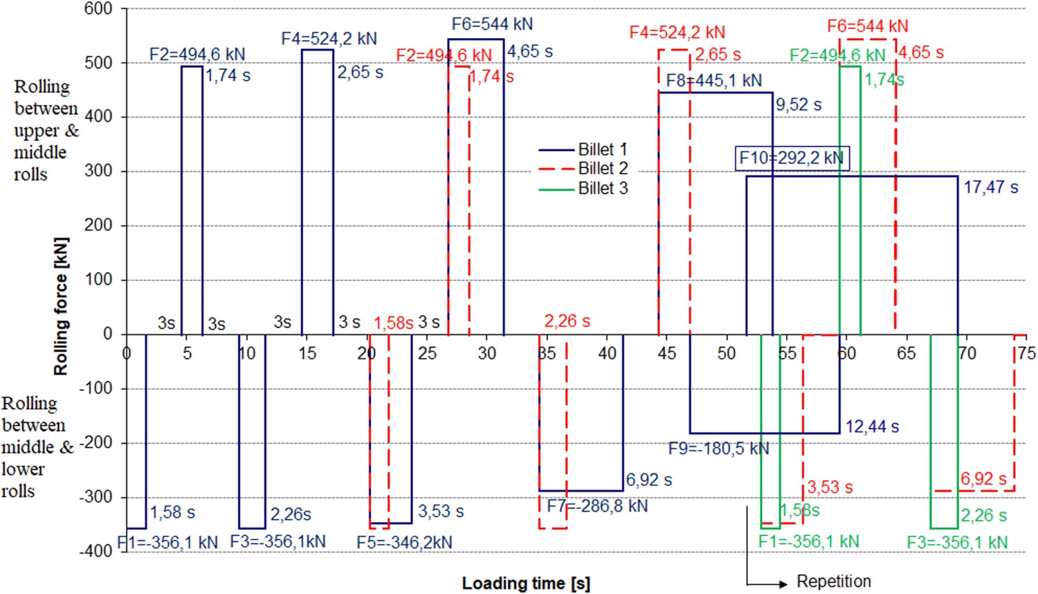
Bending stresses
The local stresses were obtained by the finite element method using ADINA software. Linear elastic model with 3D solid elements with eight DOF per nodes was used (Figure 7). Each node had 3 degrees of freedom, translation in X, Y and Z direction. The model was fixed on both ends in the line and loaded with concentrated forces in the nodes (Figure 7). Bending stresses obtained by numerical analysis for 12 cases of loading are presented in Table 2. Stress concentration factors at critical areas are in good coherence with the literature [4]. Linear elastic model with concentrated forces in the nodes.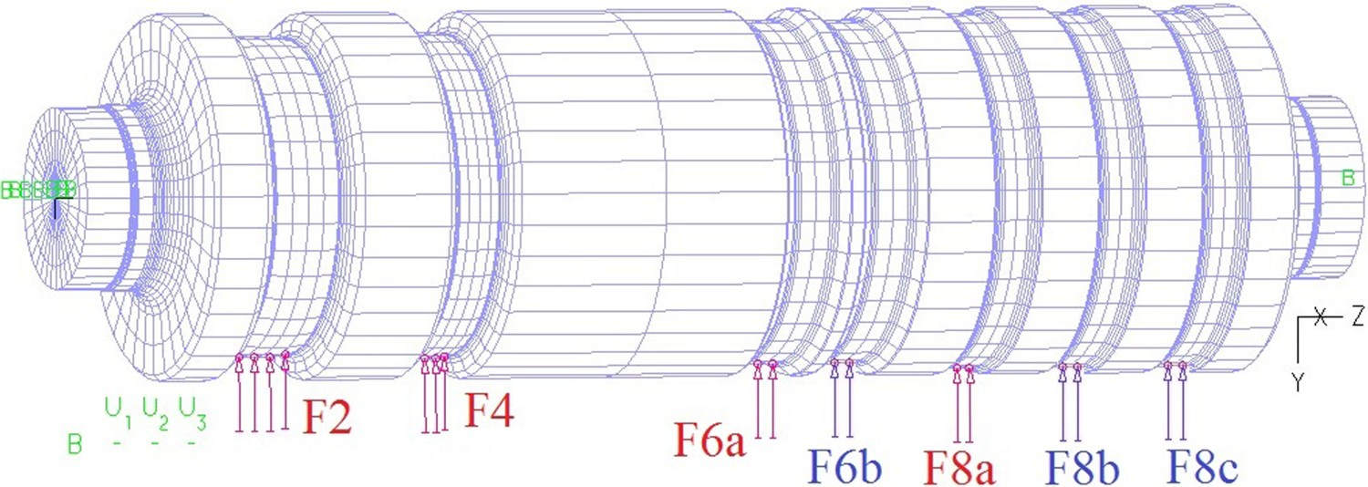
Rolling forces and bending stresses at upper roll neck during rolling.
The maximum stress occurs at the roll neck during rolling in passes 2 and 6 at the same time. Figure 8 shows FEM model of the upper roll with rolling forces 2 and 6 and corresponding stresses in direction Z. Maximum stress at roll neck.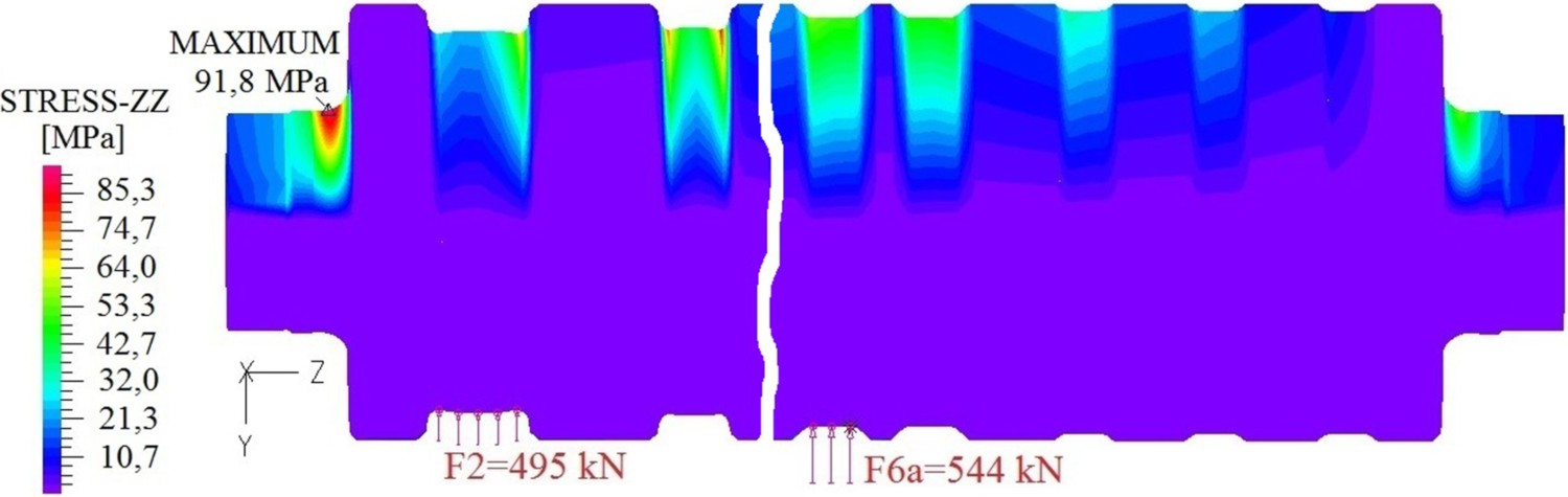
The bending stresses at roll neck also change according to time following rolling forces changes (Figure 9). Bending stresses change at upper roll neck during rolling.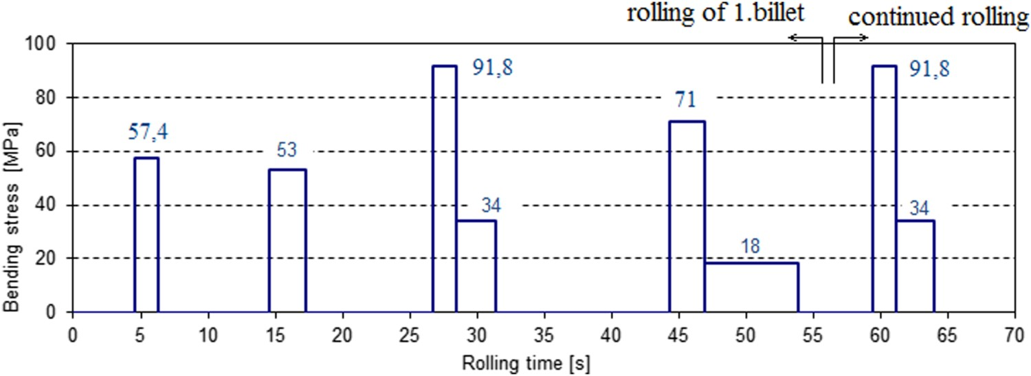
Bending stresses changes were used to obtain stress time history for the rolling of one billet and stress spectrum for rolling 4000 tons of billets (Figure 10). Stress time history for one billet and stress spectrum for rolling 4000 tons.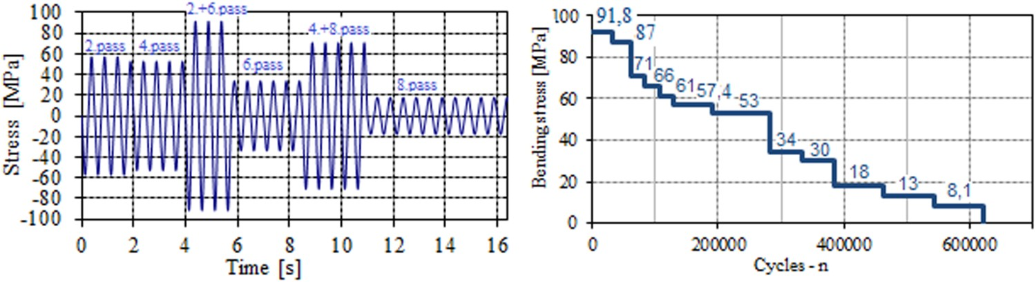
Torsional stresses
The rolling stock passes between two rolls and the torque required for deformation is the torque of two rolls (Figure 11). Rolling force and rolling deformation torque.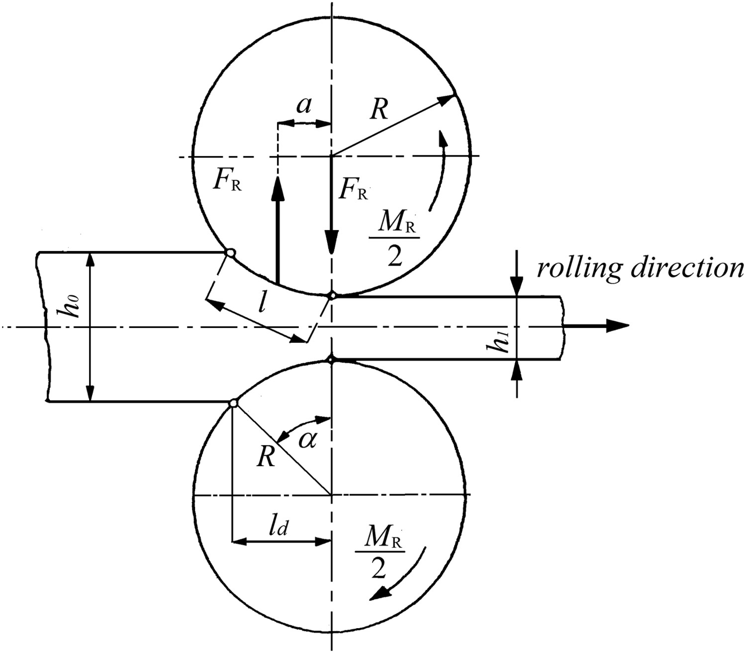
The equation for rolling deformation torque is given by
Each roll is loaded by half of the total rolling torque
Roll torque for each separate pass is obtained from Equations (1) and (2) (Table 1). The roll torque change follows the rolling sequence and the maximum rolls torque of 22.7 kNm occurs during rolling in passes 2, 6 and 10 (Figure 12). Upper rolls torque change according to time.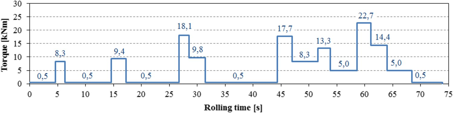
The calculated nominal shear stress for the roll diameter of 227 mm is 9.7 MPa. The stress concentration factor due to torsional stress at the change of the shaft diameter according to the literature [4] is 1.34. The maximum shear local stress at the intersection of the change of the shaft diameter due to stress concentration was 13 MPa. From the comparison between bending and shear stresses it is visible that bending stresses were dominant for the roll fracture.
Influence of rolling temperature
During the investigation of failures, it was observed that rolling stock did not have requested temperature. The measurement of the rolling temperature by manual pyrometer showed decreasing of the initial rolling temperature from 1200 to 1000°C. The result of decreasing the initial rolling temperature is increasing of the rolling forces (Figure 13; [5]). Influence of rolling temperature on rolling force.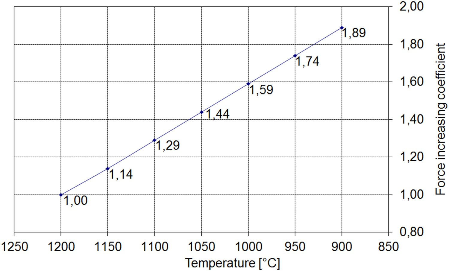
The influence of decreasing the initial rolling temperature from 1200 to 1000°C on stress spectrum is shown in Figure 14. Three stress spectra are shown; the basic stress spectrum for the initial rolling temperature 1200°C and 4000 rolling tons of production, stress spectrum for the inlet temperature 1000°C and 5000 rolling tons of production and stress spectrum for the initial rolling temperature 1200°C and 16000 rolling tons of production. 4000 rolling tons is estimated time of the roll service life before machining due to wearing of pass groves. 5000 rolling tons is the service life of broken roll. 16,000 rolling tons is the estimated service life of the roll. Experimentally determined fatigue strength curve of the material was used from literature [6]. Influence of rolling temperature decreasing on roll fatigue life.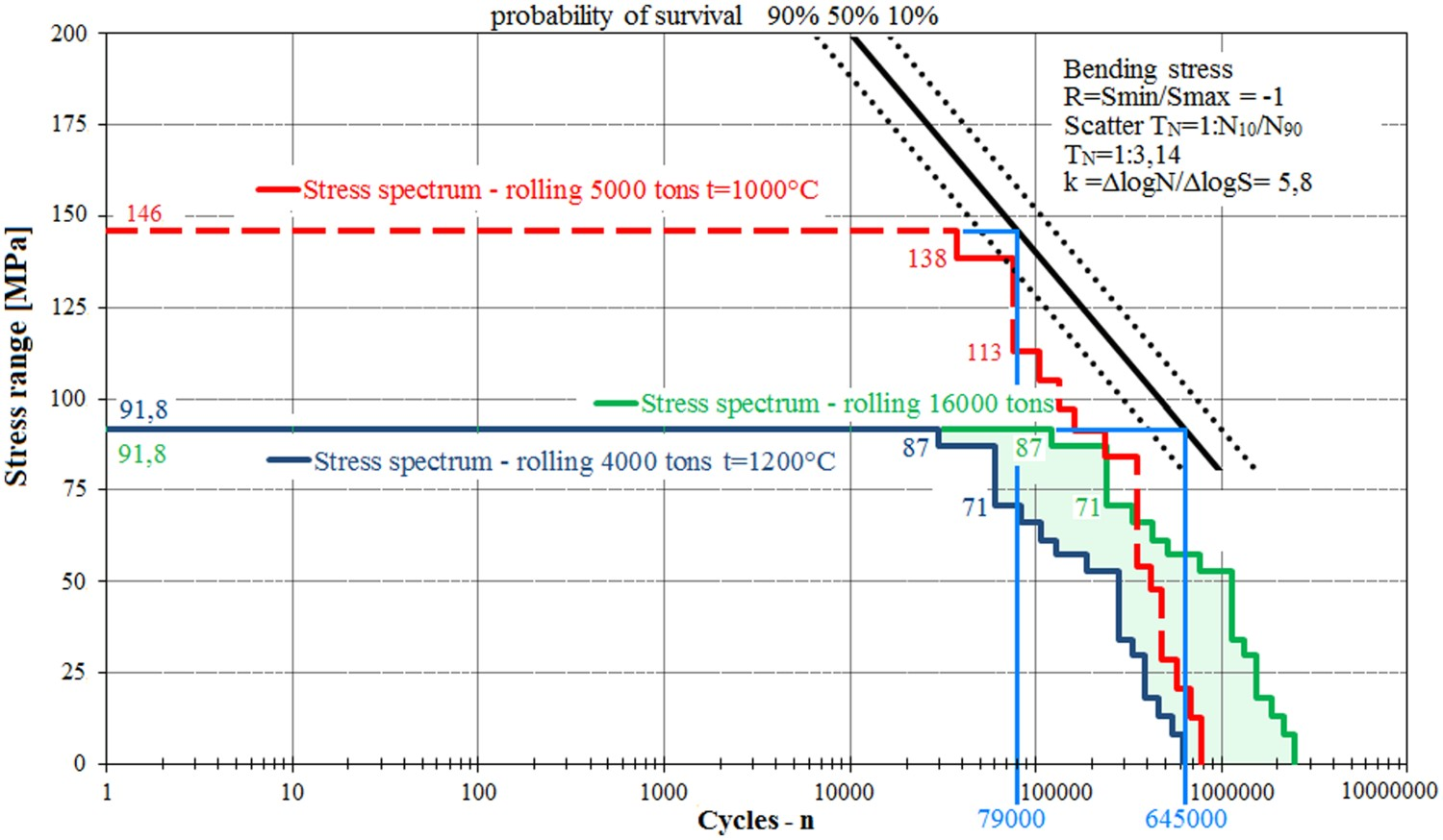
It can be seen from the curves shown in Figure 14 that fracture of the roll neck during the rolling of 5000 tons with initial temperature 1200°C should not occur.
Decreasing of the initial rolling temperature from 1200 to 1000°C increases the maximum stress at roll neck from 91.8 MPa to 146 MPa (1.59 time) and reduces roll fatigue life from 645,000 cycles to 79000 cycles (about 8 times). The curve of material for 50% probability of survival is taken for reference. The bending overload which caused the roll fracture was the result of decreasing the initial rolling temperature.
Proposed design modifications
From Figure 14, it is obvious that the stress spectrum for 16,000 rolling tons of production is very near of reaching Wöhler curve. In order to reduce energy costs by decreasing the rolling temperature, design modifications of the roll were considered without change of the sealing part or with some small modification (Figure 15): Roll neck detail B.
Three groups of design modifications were considered to decrease stress concentration: Increasing size of the fillet radius from 30 mm to 40 and 45 mm (Figure 16); Using angular fillets of 30, 40 and 45 mm with radii 5 mm on the ends (Figure 17) and Using elliptical shoulder fillets with two radii (Figure 18). Fillet radius; (a) 30 mm, (b) 40 mm and (c) 45 mm. Angular fillets with radii on the ends. Elliptical fillets with two radii.
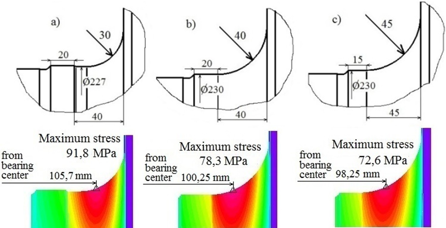
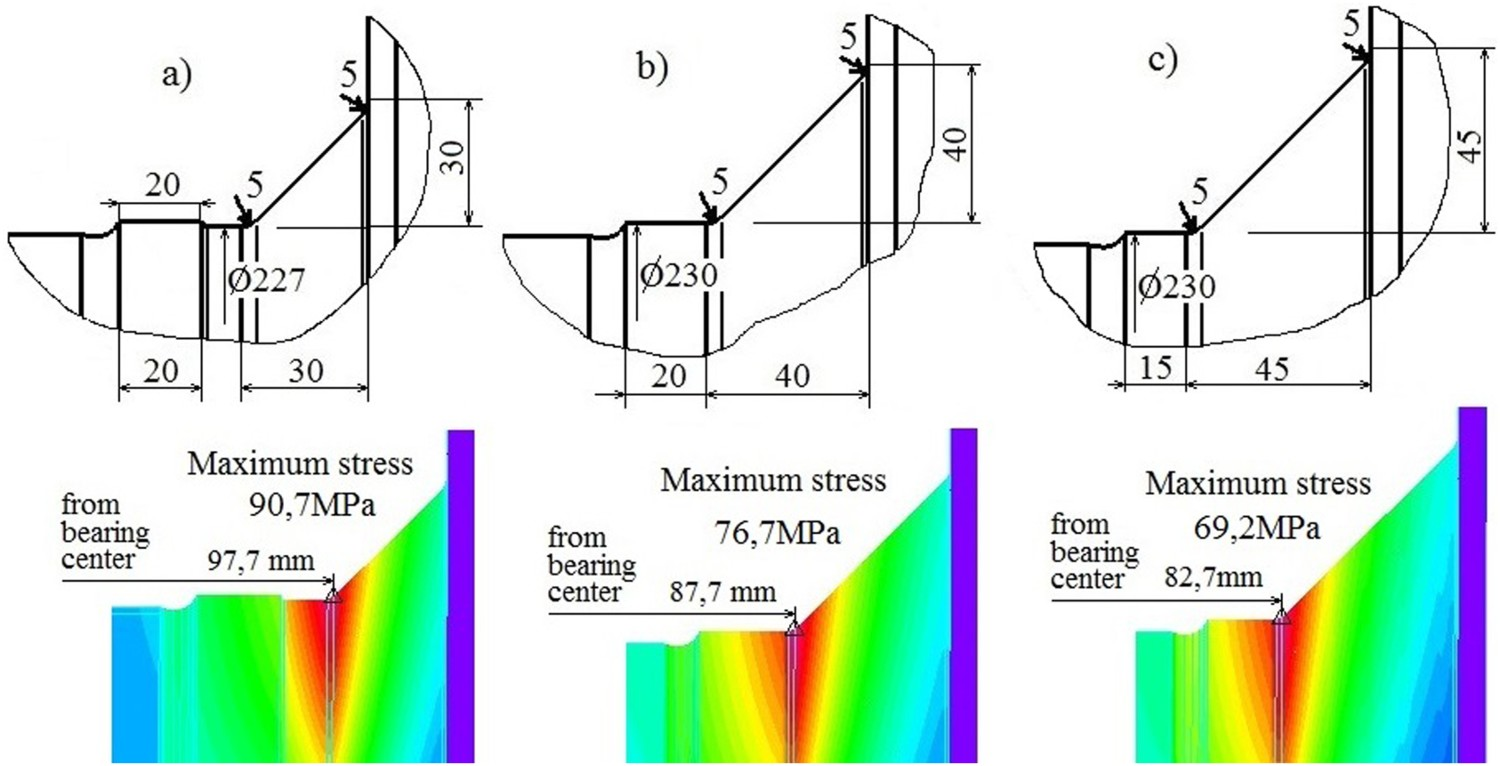
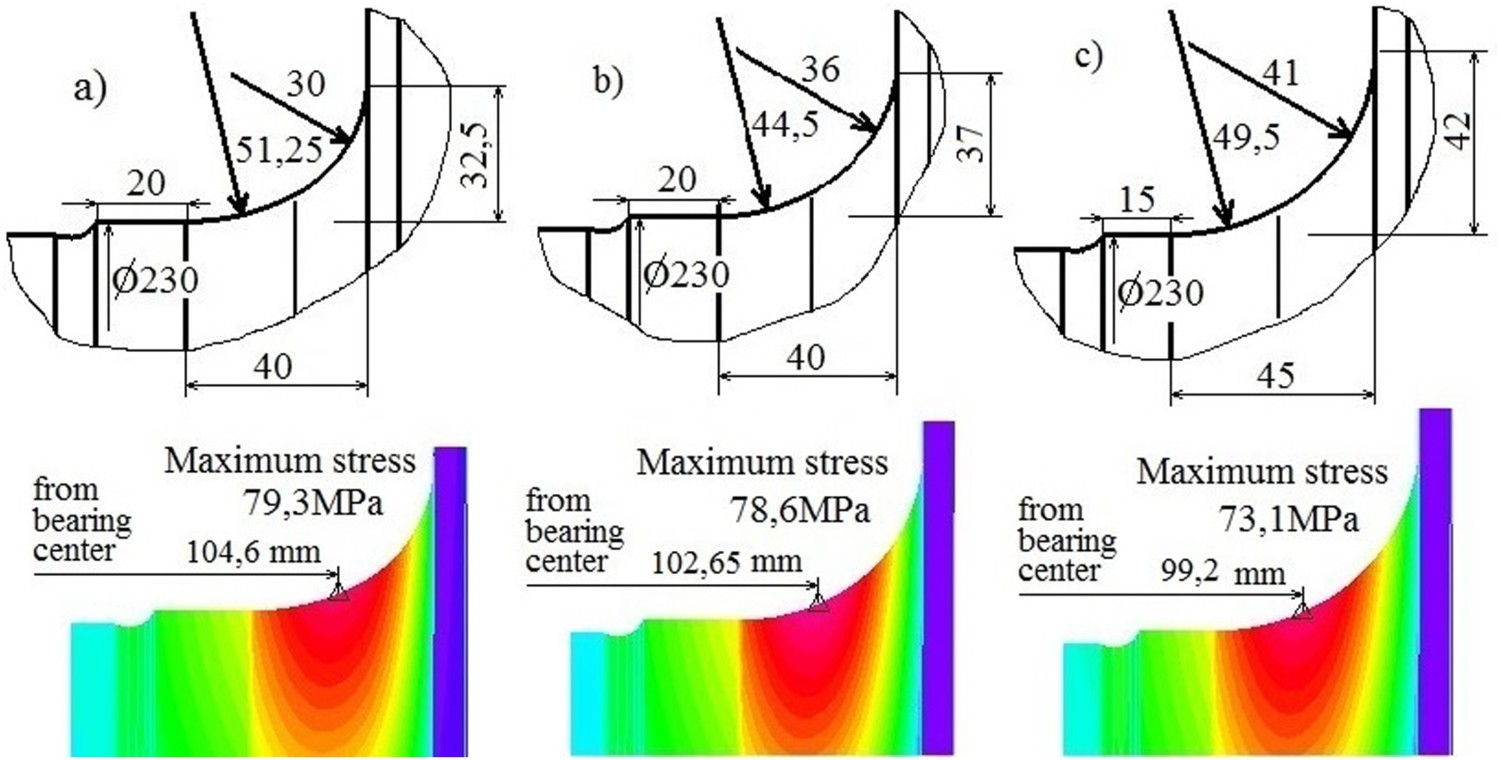
FEM analysis of local stresses revealed that redesign of the fillet radius 30 mm (Figure 16(a)) decreases the maximum stress from 91.8 MPa to; 78.3 MPa by increasing radius to 40 mm (Figure 16(b)); 72.6 MPa by increasing radius to 45 mm (Figure 16(c)); 90.7 MPa by angular fillet 30 mm (Figure 17(a)); 76.7 MPa by angular fillet 40 mm (Figure 17(b)); 69.2 MPa, by angular fillet 45 mm (Figure 17(c)); 79.3 MPa by elliptical fillet with radii 51.25 and 30 mm (Figure 18(a)); 78.6 MPa By elliptical fillet with radii 44.5 and 36 mm (Figure 18(b)) and 73.1 MPa by elliptical fillet with radii 49.5 and 41 mm (Figure 18(c)).
Each design modification also changes the position of the maximum stress according to bearing.
Influence of design modification on fatigue life
Fatigue life for design modification with inlet temperature 1200°C
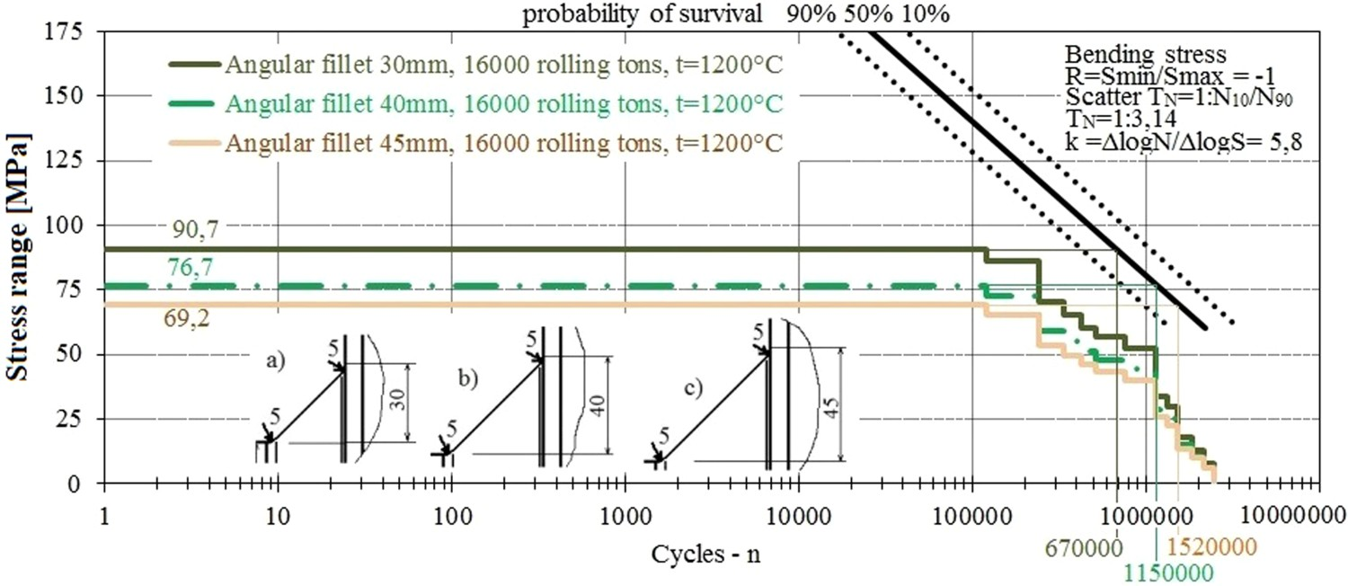
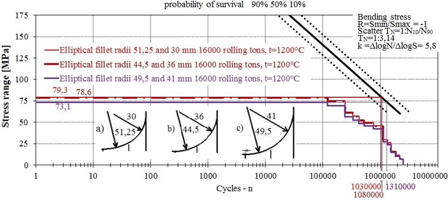
Stress spectra for the design modifications were determined from the numerical analysis and rolling sequence. Stress spectra with inlet temperature 1200°C for the shoulder fillets with radii 30, 40 and 45 mm are shown in Figure 19, for the angular fillets 30, 40 and 45 mm in Figure 20 and for the elliptical fillets in Figure 21. Roll fatigue life with shoulder fillets with radii 30, 40 and 45 mm. Roll fatigue life with angular fillets 30, 40 and 45 mm. Roll fatigue life with elliptical fillets.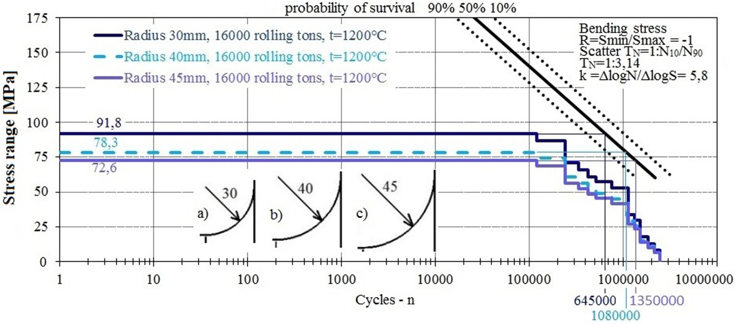
Increasing the size of the roll fillet radius from 30 mm to 40 mm (Figure 19), can extend the roll fatigue life 1.67 time, from 645,000 cycles to 1,080,000 (1,080,000/645,000 = 1.67). Additional increasing of the roll fillet radius to 45 mm extends the fatigue life of roll more than twice (1,350,000/645,000 = 2.09).
The redesign of fillet radius of 30 mm by angular fillet of 30 mm with radii on the ends (Figure 20) can extend the roll fatigue life by little, (from 645,000 cycles to 670,000). The redesign by angular fillet of 40 mm can extend the fatigue life 1.78 time, (1,150,000/645,000 = 1.78), while redesign by angular fillet of 45 mm can extend the roll fatigue life more than twice (1,520,000/645,000 = 2.36).
The design modification using elliptical fillet (Figure 21), with radii 51.25 and 30 mm can extend the roll fatigue life 1.6 time (1,030,000/645,000 = 1.6). The redesigning by using elliptical fillets with radii 44.5 and 36 mm can extend the roll fatigue life 1.67 time (1,080,000/645,000 = 1.67). The design modification using elliptical fillet with radii 49.5 and 41 mm can extend the roll fatigue life twice (1,310,000/645,000 = 2.03).
Fatigue life for design modification with decreased inlet rolling temperature
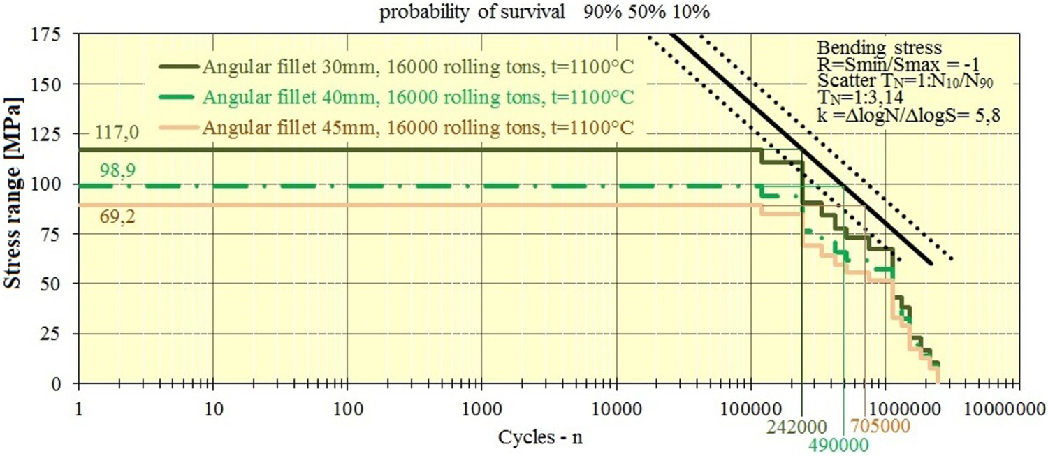
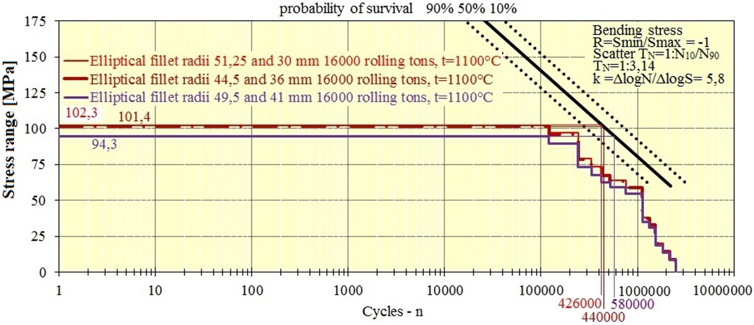
Decreasing rolling temperature reduces the fatigue life as shown in Figure 14. For the initial rolling temperature 1200°C, design modifications considered in the previous section extend roll fatigue life. The possibility of rolling with design modifications and initial rolling temperature 1100°C was analysed in order to reduce the cost of energy. Stress spectra for initial rolling temperatures 1100°C were determined from the numerical analysis and rolling sequence; for shoulder fillets with radii 30, 40 and 45 mm are shown in Figure 22; for angular fillets 30, 40 and 45 mm in Figure 23 and for elliptical fillets in Figure 24. Roll fatigue life with radii 30, 40 and 45 mm for t = 1100°C. Roll fatigue life with angular fillets 30, 40 and 45 mm for t = 1100°C. Roll fatigue life with elliptical fillets for t = 1100°C.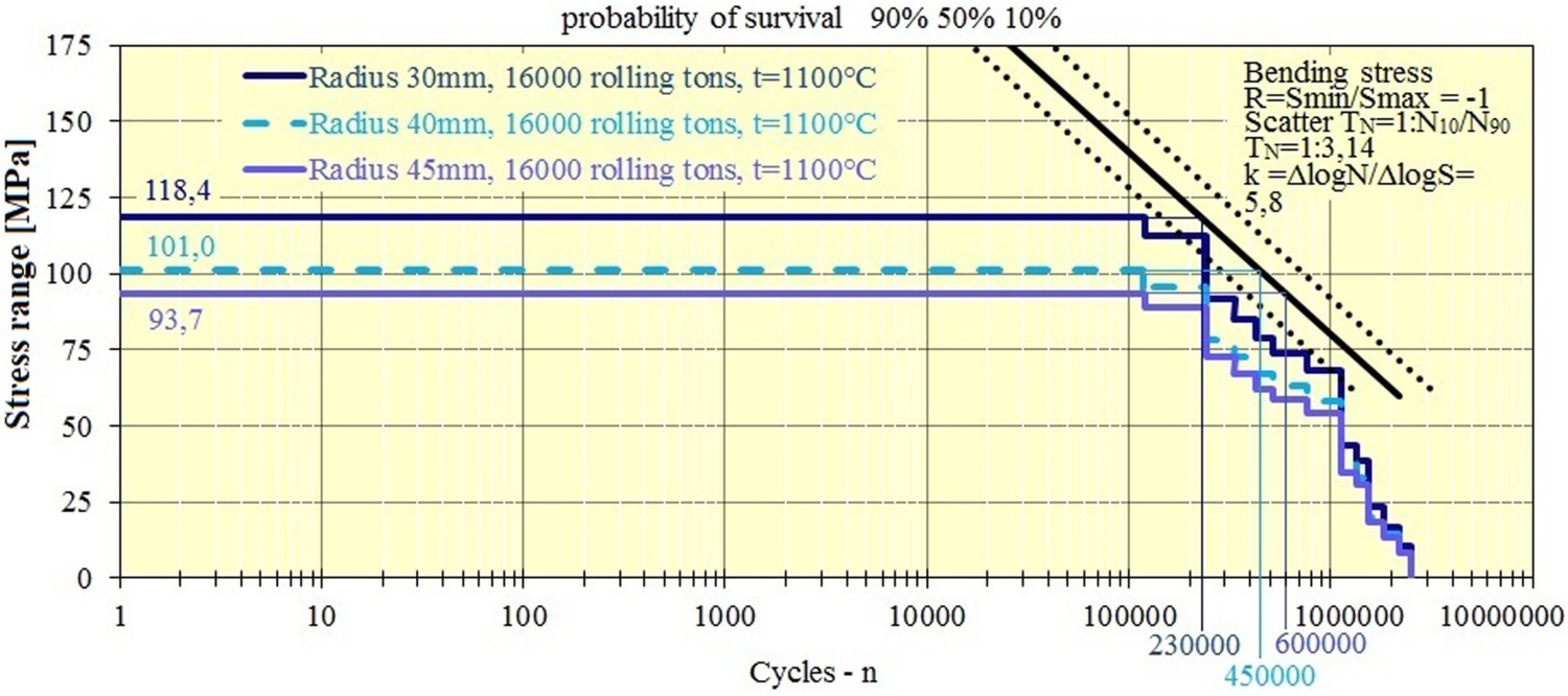
Rolling with decreasing the initial temperature from 1200°C to 1100°C increased the rolling force 1.29 time (Figure 13), and proportionally increased the maximum stress at the roll neck and reduce the roll fatigue life (Figures 22–24).
The fatigue life of the roll neck with radius 30 mm for initial rolling temperature 1100°C was reduced 2.8 times (645,000/230,000 = 2.8); 2.4 times with radius 40 mm (1,080,000/450,000 = 2.4) and 2.25 times with radius 45 mm (1,350,000/600,000 = 2.25).
The fatigue life of the roll neck with angular fillet 30 mm was reduced 2.77 times (670,000/242,000 = 2.77); 2.35 times with angular fillet 40 mm (1150000/490000 = 2.35) and 2.15 times with angular fillet 45 mm (1,520,000/705,000 = 2.15).
Finally, the fatigue life of the roll neck with the initial rolling temperature 1100°C for elliptical fillet with radii 51.25 and 30 mm was reduced 2.41 times (1,030,000/426,000 = 2.41); 2.45 times with elliptical fillet with radii 44.5 and 36 mm (1,080,000/440,000 = 2.45 times) and 2.26 times with elliptical fillet radii with 49.5 and 41 mm (1,310,000/580,000 = 2.26).
Results overview and conclusion
The roll neck fracture was the result of the rotational-bending fatigue caused by bending overload due to uncontrolled decreasing of the rolling temperature. Three groups of design modifications of the roll neck were considered to decrease the maximum local stresses and increase the roll service life. With intention to reduce energy consumption by controlled decreasing of inlet rolling temperature. The overview of the results is shown in Figure 25. Results overview.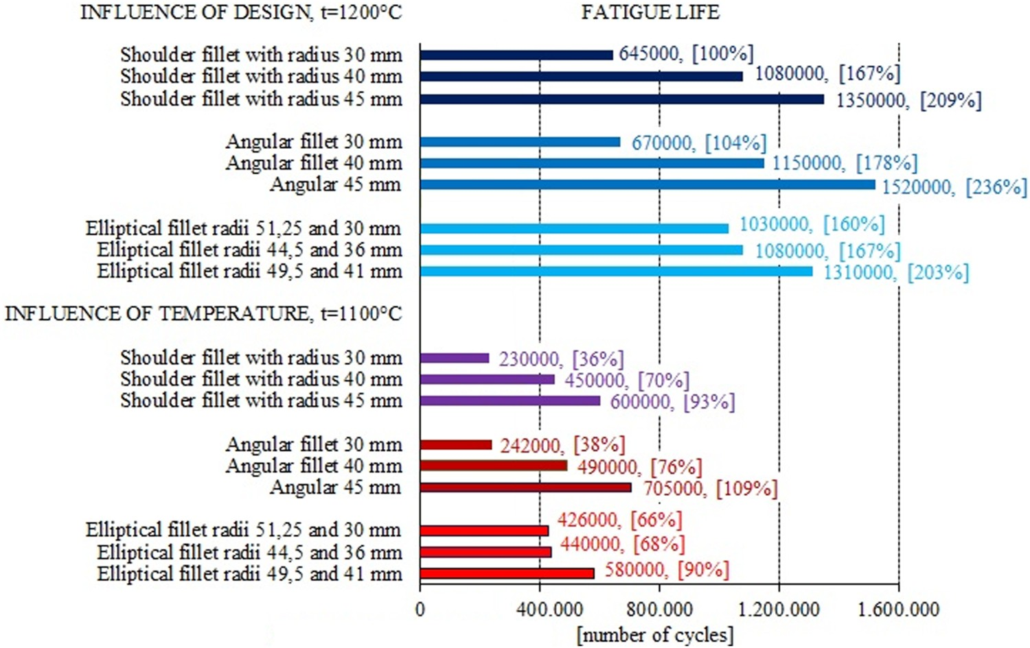
It is visible from the results that the shape of the roll neck has a huge influence on the roll neck fatigue life. Difference in fatigue life between two design solutions can be almost 3 times (from 230,000 cycles to 705,000) in the same rolling conditions.
The maximum stresses for two design solutions, shoulder fillet with radius 30 mm and angular fillet 30 mm, with inlet temperature 1100°C can cause roll neck fracture.
Two design solutions; shoulder fillet with radius 45 mm and elliptical fillet radii with 49.5 and 41 mm, can almost completely compensate negative influence of decreasing the rolling temperature to 1100°C on the roll fatigue life.
The design solution with an angular fillet of 45 mm, even with inlet rolling temperature 1100°C can extend the roll fatigue life. For other designing solutions rolling with temperature 1100°C will reduce fatigue life but should not lead to fracture.
Selecting the appropriate design solution, such as shown, in the case of rolling with controlled decreasing of the inlet rolling temperature will not lead to fracture and energy consumption and coresponded overall costs will be reduced.