
Abstract
The effects of cooling modes (air, furnace and water) on the variation of microstructure and mechanical properties of medium carbon steel were investigated. SEM, TEM and EBSD techniques were used to observe the microstructure. The observed results show that the effect of cooling mode on the grain size is insignificant. The average sizes of ferrite grain obtained under different cooling modes were little different. Moreover, in all the cases, most of the cementite lamellas were transformed into cementite particles, except for some of the residual cementite lamellas which were present on the original pearlite colonies. It has also been found that the ferrite substructure and precipitation of cementite particles are significantly affected by the cooling modes. Compared to other cooling modes, the furnace cooling is beneficial to the homogeneity of microstructure. The particles are distributed on the ferrite matrix more homogeneously after furnace cooling which results in a better combination of strength and ductility.
Introduction
The medium carbon steel is widely used in the areas of bridge, mechanical engineering, aerospace industry, vehicle, etc. To reduce the cost, it is important to decrease the parts weight of medium carbon steel by improving the mechanical properties. Grain refinement is one of the efficient means to improve the properties of alloys [1–3]. The methods for preparing ultrafine grains can be mainly divided into two categories: severe plastic deformation (SPD) and dynamic mechanical thermal treatment (DMTT) [4]. The SPD processing mainly includes the equal channel angular extrusion (ECAE) [5], accumulated rolling process (ARP) [6], high-pressure torsion (HPT) [7], etc. The SPD can generate ultrafine grains even in the nanometer scale in the laboratories. The DMTT process is suitable for preparing the billet with large size [8]. However, the traditional DMTT only refines the grains into micrometer grade.
For preparing sub-micrometer grains, Wang et al. [9,10] compressed original microstructure composed of martensite or banite at the temperature range of 550–700°C. However, this method required high cooling and reheating rates before warm compression. Owing to this, another method was proposed to obtain sub-micrometer grains where the medium carbon steel with the microstructure composed of ferrite and pearlite was deformed under medium range of temperatures [4,11]. But, the strength increases at the expense of ductility and uniform elongation if the grain size is about 1 μm [4]. Thus, the ductility is enhanced by means of bimodal grain size [12], nano-scale twins [13], hard particles pinning effect [14,15], ductile phase [16,17], etc. The preparation with bimodal grain size and nano-scale twin is difficult in production of iron and steel [18]. The transformation induced plasticity (TRIP) and twin induced plasticity (TWIP) effects need the ductile phase (residual austenite) to increase the ductility with higher Mn and/or C content and also involves tedious heat treatment [19–21].
Torizuka et al. [15] indicated that the effect of carbon content on the mechanical properties of ultrafine ferrite was significant, due to the pinning effect of carbide particles on the dislocation slip during room deformation. Storojeva et al. [11] indicated that long soaking time (about 2 h) is beneficial for the formation of homogeneous microstructure and the precipitation of carbide particles. It indicated that the process of warm rolling and long soaking time could obtain the excellent combination of strength and ductility. But the soaking process is too long to be unpractical in the production process and may cost lots energy.
If the proper cooling mode is adopted after warm rolling, the long soaking process may be replaced. Therefore, it is necessary to investigate the influence of cooling mode on the mechanical properties. In this paper, the different cooling modes after warm rolling test were carried out, and the effect of cooling behaviour (as shown in Figure 1) on the microstructure and mechanical properties were studied based on the observation of microstructure and by the tensile test at room temperature. Scheme of rolling test.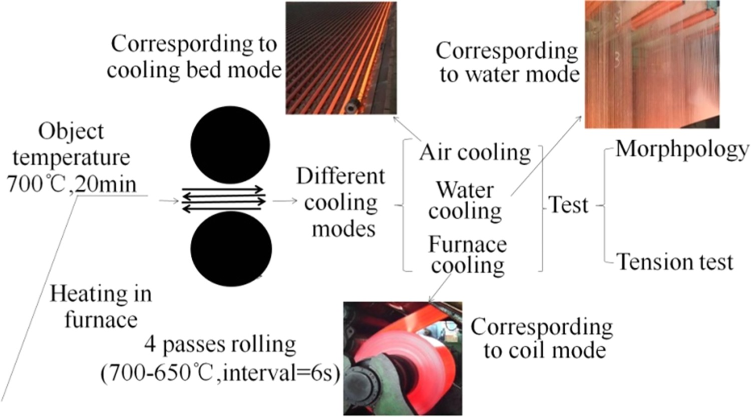
Experimental
The test steel (0.46C, 0.23Si, 0.72Mn, 0.03P, 0.03S, Fe: bal. (wt-%)) was used and the size of specimens for warm rolling was 23 × 45 × 100 mm. The original microstructure composed of ferrite and pearlite with the size of ∼20 μm, as shown in Figure 2(a). The rolling scheme is shown in Figure 1 and the details are given in Table 1. The test specimens were heated up to the target temperature of 700°C and soaked for 20 min in the furnace. The rolling tests were carried out on a ϕ350×350 mm reversible rolling mill. After warm rolling, the deformed specimens were cooled to room temperature by different cooling modes, i.e. air, furnace air and water. The specimens for the tensile test and microstructure observations were cut at the centre of the rolled piece. The tensile tests were carried out using a universal tester (INSTRON-3380, INSTRON, Norwood, MA, USA) at speed of 2 mm min−1. The tension test was carried out three times per cooling mode at room temperature to weaken the experimental error. The free gauge of tension samples is 2 × 4 × 50 mm3. The microstructure of centre area was observed by scanning electron microscopy (SEM, Nova NanoSEM430, FEI, Boston, MA, USA), electron back-scattered diffraction (EBSD, Oxford NORDLYS 2S, Oxford, UK) and by transmission electron microscopy (TEM, Tecnai G2 F20, FEI, Boston, MA, USA). The sample for microstructure observation was cut at the centre of the rolled pieces, and the surface was observed. The fracture morphology was analysed by SEM. The specimens for the observation of microstructure by using SEM were obtained by mechanical polishing and by etching which was carried out in a 4% nital solution. The orientation of the image was analysed by EBSD. The samples for EBSD were mechanically polished and subsequently polished electrolytically. The scan step was 0.15 μm. The low angle boundaries (LABs) are defined from 2° to 15° (shown as grey lines), and the high angle boundaries (HABs) are above 15° (shown as black lines). For TEM the samples were cut into a thickness of 0.5 mm and mechanical grinding was followed to obtain with the thickness of 30 μm, which was subsequently thinned to perforation by ion-beam milling. Microstructure before and after warm rolling (a) original microstructure and (b) microstructure after warm rolling.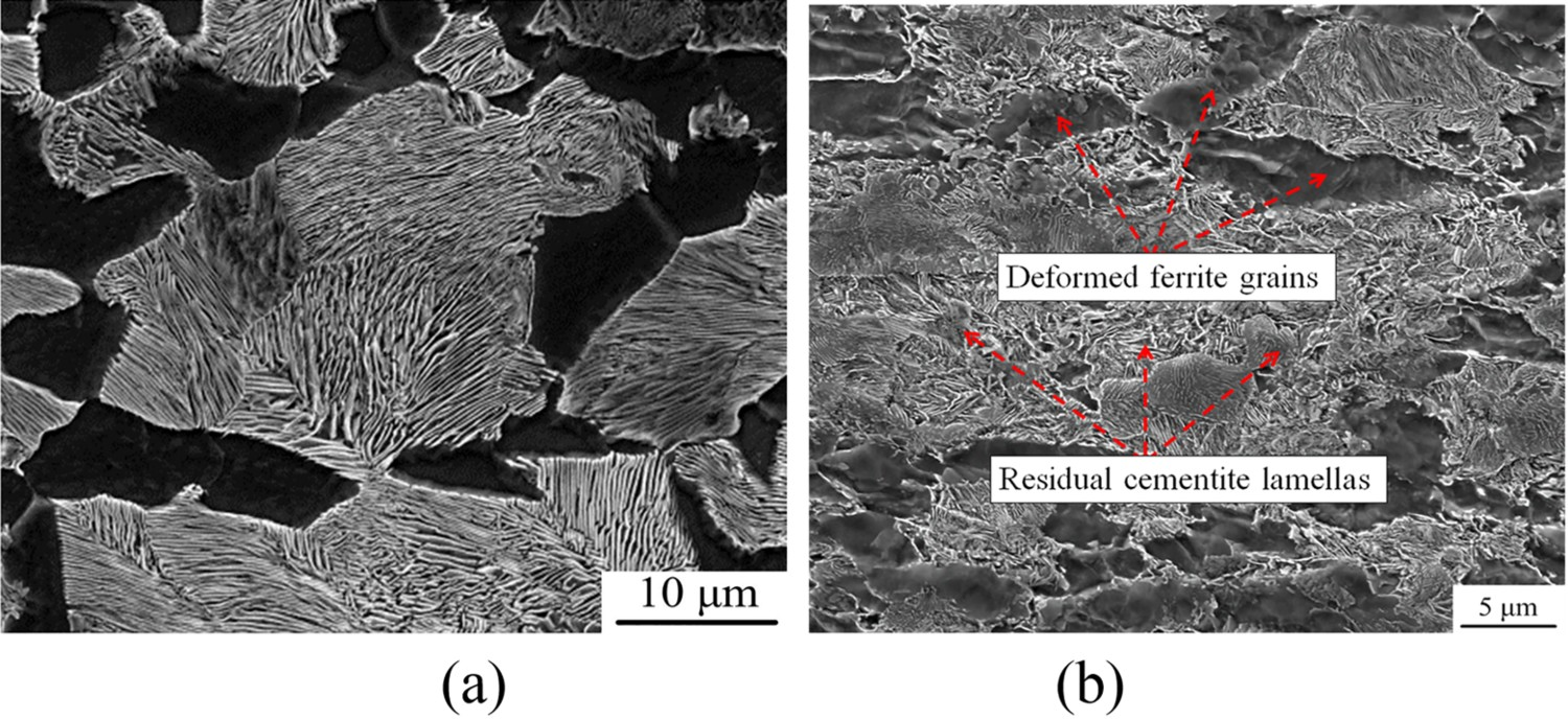
Deformation scheme of rolling test.
Results
Effect of deformation and cooling mode on the microstructure
The microstructure after four passes of rolling is shown in Figure 2(b). The difference between ferrite and pearlite colonies is clear and the size of ferrite grains and pearlite colonies decreases after warm rolling [11,22]. No complete cementite lamellas could be found out in the matrix. Some cementite lamellas are fractured and transformed into carbide particles and distributed in the initial pearlite colonies and precipitated on the ferrite grain boundaries. Some short rodlike cementite lamellas are distributed in the original pearlite colonies. The polygonal ferrite grains transformed into a pancake type and there are some sub-grains in the ferrite grains. The microstructures obtained after different cooling modes are shown in Figures 3 and 4. As shown in Figure 3, the effect of cooling mode on the microstructure is noticeable. With the decreasing cooling rate, the fraction of sub-structure decreases. Moreover, more of the carbide particles are precipitated in the ferrite matrix. There are large numbers of residual cementite lamellas in the initial pearlite colonies after water cooling. Meanwhile, there are many dislocation groups remain in the ferrite grains. During air and furnace cooling, the density of sub-grain boundaries relatively decreases as compared to water cooling and some of the cementite particles precipitate in the ferrite matrix as shown in Figure 3(a,c). Morphology using TEM under different cooling modes (a) air cooling; (b) water cooling; (c) furnace cooling. Boundaries map after different cooling modes air cooling; (b) water cooling; (c) furnace cooling (black lines represent the HAGs, whereas grey lines represent the LAGs).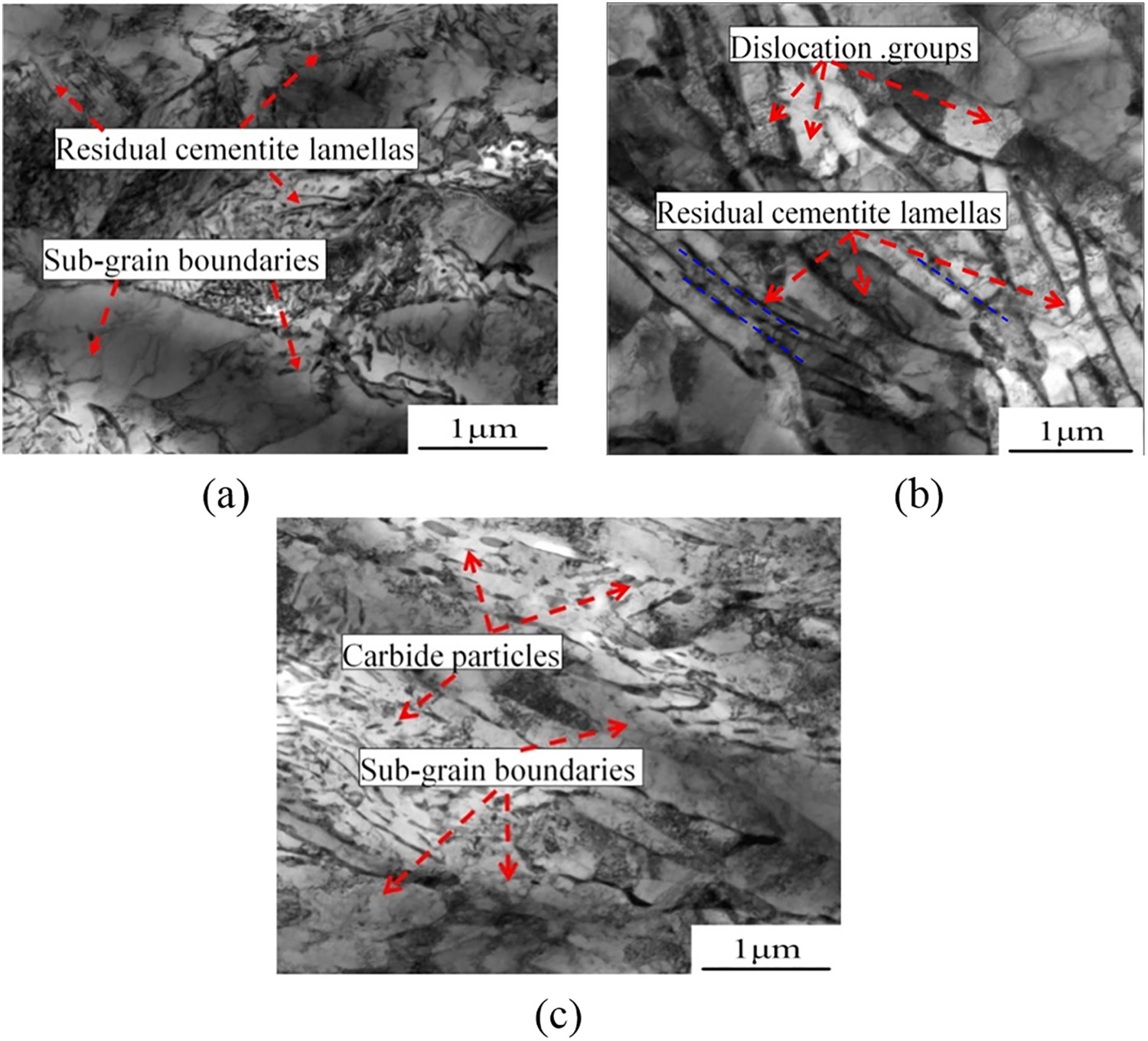
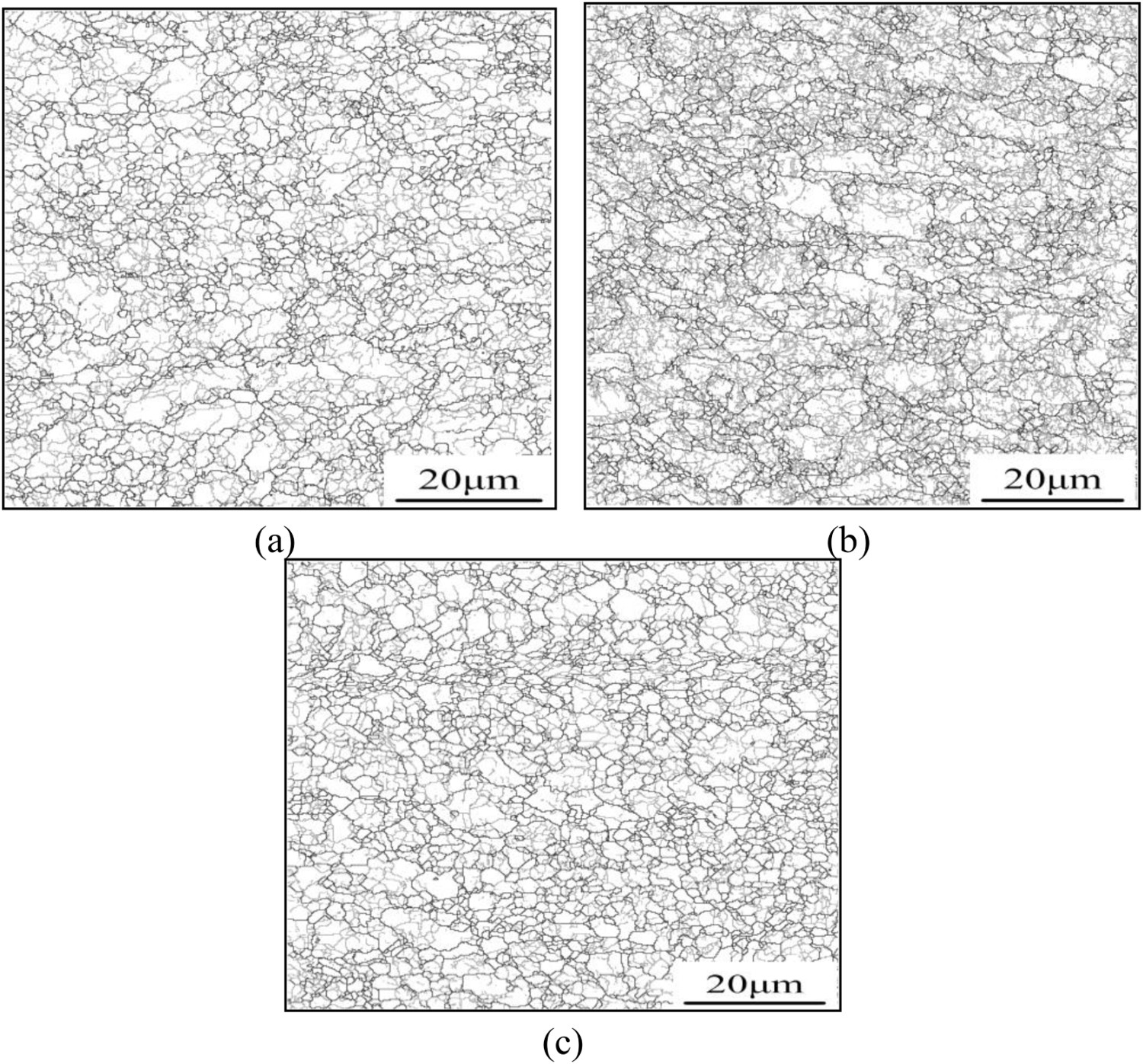
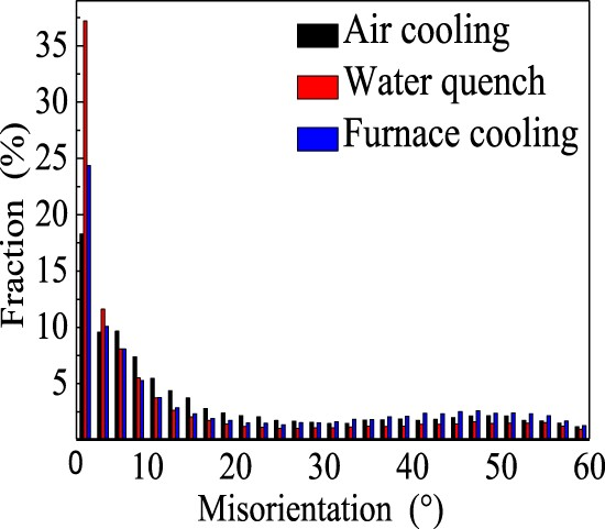
The boundary map of warm rolled ferrite grains after different cooling modes is shown in Figure 4. It can be found that the LABs density in specimen of water cooling is the highest, followed by air and furnace cooling. It indicates that the effect of cooling mode on the sub-structure evolution is substantial. The high cooling rate is beneficial to the preservation of sub-grains which were formed during the rolling. The size of ferrite grain is shown in Figure 5. The fraction of sub-micrometer grains after water, air and furnace cooling is about 62%, 58% and 48%, respectively. It indicates that many sub-grains transformed into grains by absorbing the dislocations (namely continuous static recrystallization) and grow larger than 1 μm during low rate cooling, such as furnace cooling process. As shown in Figure 6, the LABs fraction of water cooling is the highest which is about 63.9%, whereas the LABs fraction of air and furnace cooling is about 54.8% and 53.2% respectively. Distribution of grain size after different cooling modes. Distribution of misorientation for different cooling modes.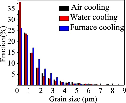
Effect of cooling modes on the mechanical properties
The tensile curves are shown in Figure 7 and the tensile properties including strength and ductility are shown in Table 2. The ultimate tensile strength (UTS) of furnace and air cooling is less than the values reported by Lv et al. [4] and Li et al. [23]. It may be attributed to the added chemical composition of carbon, molybdenum and chromium. Another reason may be due to the composition of phases as the samples deformed in the two-phase region followed by water quenching. The UTS of all the cooling modes is more than the already reported [18,24]. It may be caused by the difference in the size of ferrite grain and carbide particles. The sample obtained with water cooling shows the highest strength and poorest ductility. The difference in strength between furnace and air cooling is small. The sample after furnace cooling possesses better mechanical properties than after subjected to air cooling, which indicates that the furnace cooling may be the best cooling mode for the medium carbon steel after warm rolling. Tensile curves obtained from different cooling modes after warm rolling.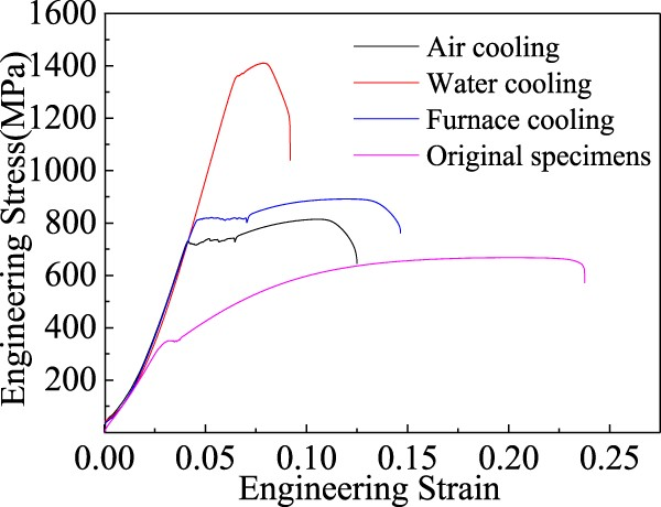
Tensile mechanical properties.
Discussions
The size of ferrite grains during warm rolling decreased with the increasing strain, and some residual cementite laminates which remained, as shown in Figure 2. It is attributed to the initial orientation of cementite lamellas [11]. If the initial orientation of lamella is perpendicular to the deformation direction, it is good for the cementite lamellas preservation [25–28]. During deformation, the ferrite is softer than pearlite. Therefore, the deformation is concentrated on the ferrite colonies. Most of the dislocations fill in the boundaries of pearlite and ferrite. The dislocations and vacancies formed during deformation contribute to the diffusion of carbon atom [12]. It promotes the decomposition of lamellas and the residual lamellas transformed into particles or short rods, which are linearly arranged in the direction of initial lamellas as shown in Figure 3(b) (the blue lines). It demonstrates the characteristic microstructure of medium carbon steel after warm deformation [26].
During cooling, the annihilation of dislocations occurs and the carbon atoms diffuse into the low carbon regions through dislocation channels and the carbon atom may precipitate in the form of particles [12]. Therefore, the cooling modes affect the diffusion of carbon atoms and cementite precipitation. The rate of water cooling is so high that there is no time for the annihilation of dislocations and recovery. Thus, the dislocations and sub-grain boundaries formed during warm rolling remain in the ferrite matrix as shown in Figure 3(b). In the low rate cooling process (i.e. air and furnace cooling), the recovery occurs, and the density of cementite particles increase in the ferrite region [11]. During cooling, some newer LABs formed by absorbing the dislocations [22]. It contains more LABs than the air cooling model, as shown in Figure 6. Meanwhile, some of the sub-grain boundaries during their formation and cooling absorb the dislocations. It results in an increase in the misorientation between sub-grains. If the misorientation exceeds15°, the sub-grains can be regarded as normal grains with HABs.
Owing to the difference of microstructure after different cooling modes (as shown in Figure 3), the distinction of mechanical properties is obvious, as shown in Figure 7. The high-density dislocations and sub-grain boundaries result in the highest strength and poorest ductility, as the high-density dislocations in the ferrite grain decrease the space of interaction of dislocations and shortens the distance of dislocations glide during the tensile test [10,29]. It deteriorates the plastic deformation and reduces the accumulative space of dislocation. During tensile test, the crack emerges, once the dislocation density reaches a critical value [24].
With the decreasing cooling rate, the strength decreases whereas the ductility increases. But the sample suffered furnace cooling exhibits higher strength and ductility than the samples subjected to air cooling, as shown in Figure 7. It may be attributed to the influence of cementite particles and the lower density dislocation [15]. In the furnace cooling ferrite grains, there is more space for the accumulation of dislocation and therefore it possesses better ductility. The cementite particles play an important role of pinning effect [14,15]. It increases the dislocations slipping resistance. So it shows higher strength. Based on the results of Ref. [30], the fluting effect and yield point elongation can be decreased by adding some boron element into the carbon steel; and it increases the strength and ductility further simultaneously. Meanwhile, the effect of warm rolling process parameters on the microstructure and mechanical properties is significant. It should be further studied that the effect of coupling rolling process parameters and cooling modes on the microstructure and mechanical properties.
With regard to the water cooling mode, the ductility is little; the strain hardness curve can be ignored. Figure 8 shows the SHR of furnace and air cooling, which can be divided into three stages. During the first two stages, the SHR decreases sharply with the increasing stress, but the duration is very short and thus it is not the main factor to affect the uniform elongation. During stage 3, the duration is long, which affects the uniform elongation obviously. It is well known that the stress is determined by the dislocation density and thus the evolution of dislocation density also affects SHR. Variation of SHR with different cooling modes.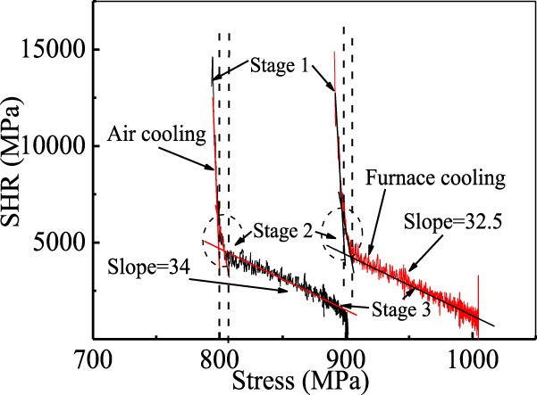
As illustrated in Figure 8, the SHR can be divided into three stages by the dashed lines, according to the variation. During stage 3, the SHR of furnace cooling is more as compared to air cooling. The rate of reduction of SHR of furnace cooling is less than that of air cooling. It is obvious that the relationship between SHR and stress is roughly negative [23] and the SHR decreases with the increasing stress.
There are more cementite particles in the matrix of furnace cooling than that of the other two cooling modes. The particles pin the dislocations and enhance the interaction between dislocations and particles during tensile test [31]. It enhances the dislocations accumulation around the particles and decreases the dislocation accumulation near the boundaries. Therefore, the specimens with homogeneous particles exhibit excellent ductility. Meanwhile, the specimens of furnace cooling show higher SHR and facilitate greater uniform elongation than the other two.
The fracture morphologies after air and furnace cooling are shown in Figure 9. The fracture surface can be divided into three regions such as shear lip, smooth and radiation. There are few thin shrink holes in the radiation region of both the cooling modes. By comparing Figure 9(a,c), the fraction of radiation region of air cooling fracture is less than that of furnace cooling fracture. It is obvious that the size and number of thin shrink holes in the radiation region of furnace cooling are less than that of air cooling. It is well known that the crack is formed by the coalescence of thin holes. The fracture morphology of cracks is different between two cooling modes. The crack surface of air cooling fracture is smooth as shown in Figure 9(b). But there are many dimples which are distributed on the crack surfaces of samples suffered furnace cooling, as shown in Figure 9(d). The dimples lead to the cracks propagation direction variation with strain. Therefore, the propagation of cracks on the dimple surface traverses more distance than that on the smooth surface. It shows that the initiation and propagation of cracks of the specimens suffered furnace cooling needs more energy than that of air cooling. Thus, the fracture with deep and large dimples represents better ductility at certain extent [32–34]. Comparison of fracture morphologies between air cooling and furnace cooling, (b) air cooling; (c), (d) furnace cooling.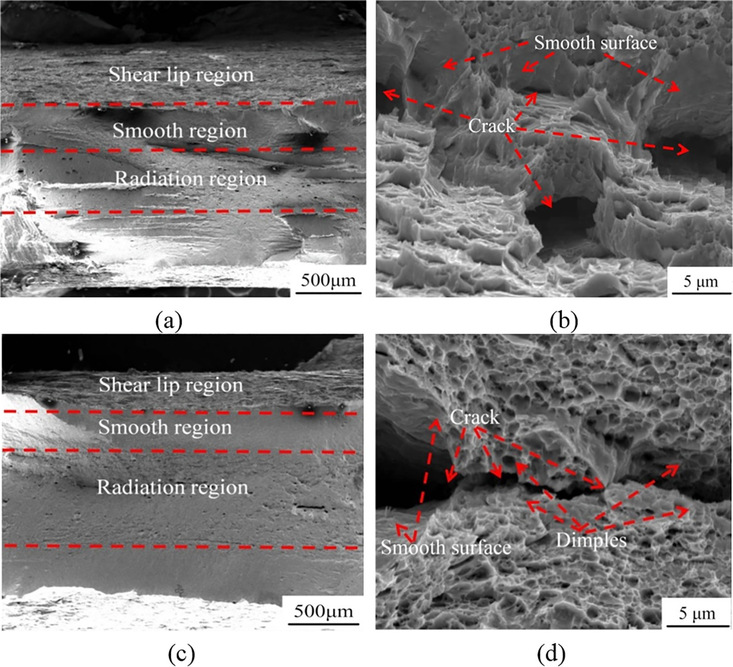
The fracture dimples of two cooling modes are shown in Figure 10. The fracture characteristics of two cooling modes belong to the ductile fracture. The main differences are the size and depth of dimples. The fracture dimples of furnace cooling are deeper and larger than that of air cooling. The formation of deep dimples costs more energy and shows better ductility than that of the shallow dimples [4,35]. The characteristics of fracture morphology are consistent with the results of tensile tests. Comparison of fracture appearance between furnace cooling and air cooling: air cooling; (b) furnace cooling.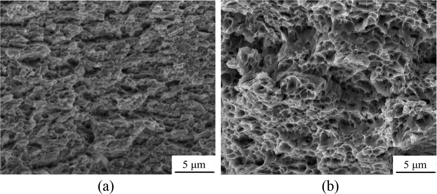
Conclusions
The effects of cooling modes on the microstructure and mechanical properties of medium carbon steel after warm rolling were studied. The main conclusions are as follows: The effect of cooling modes on the ferrite grains is little. The effect of cooling mode on substructure is significant. Compared to other cooling modes, the furnace cooling is more beneficial to the homogeneity of microstructure. During the warm rolling processing, most of the cementite lamellas transformed into particles or short rodlike. The cementite particles are distributed in the original pearlite matrix after furnace cooling. The uniform microstructure of furnace cooling results in a better combination of strength and ductility. And the SHR of furnace cooling is more than that of air cooling.
Footnotes
Disclosure statement
No potential conflict of interest was reported by the authors.