
Abstract
A mathematical model of an industrial Single Snorkel Refining Furnace (SSRF) has been developed to investigate dehydrogenation behaviour in the vacuum refining process. Dehydrogenation reactions were considered to take place at three sites: Ar bubble surface, bath surface, and the bulk steel. The effects of Ar bubble behaviour and H2 heterogeneous nucleation behaviour of the bulk steel on dehydrogenation were taken into account specifically. The simulation results are in good agreement with the measured industrial data. Using the model, the dehydrogenation rate at different sites and its contribution to total dehydrogenation value were evaluated in detail. The results indicated that bulk steel dehydrogenation occurred only the high concentration range, while the other two reactions participated in the whole refining process. In addition, the effect of argon flow rate on the dehydrogenation rate was also obtained and the reasonable range of argon flow rate for SSRF treatment has been recommended.
List of symbols
Cross-sectional area of the bath surface (m2)
Surface area of Ar bubble, area of bath surface (m2)
Heat capacity of Ar gas (5.22×10³ J kg−1 K−1)
Diffusion coefficient of dissolved hydrogen in the melt (m2 s−1)
Hole diameter of the porous plug (m)
Diameter of bath surface in the vacuum vessel (m)
Froude number
Activity coefficient of hydrogen in molten steel

Argon flow rate (L min−1, m3 s−1)
Acceleration of gravity (m s−2)
Distance from the porous plug to bath surface (m)
Critical depth of H2 nucleation in the bulk steel (m)
Distance from the position of Ar bubble, H2 nucleation site to the bath surface (m)
Elemental component ‘j’ dissolved in molten steel

Dehydrogenation rate at Ar bubble surface of the ladle, the vacuum vessel (kg s−1)

Dehydrogenation rate at Ar bubble surface, bath surface and the bulk steel (kg s−1)
Equilibrium constant of the dehydrogenation reaction
Mass transfer coefficient of hydrogen to Ar bubble surface, bath surface (m s−1)
Process parameter of inner steel dehydrogenation (s−1)
Serial number of bubble from the bottom of the ladle to bath surface of the ladle
Number of Ar bubbles in the ladle, the vacuum vessel

Number of moles of H2, Ar gas in the Ar bubble (mol)

Number of moles of H2, H2+Ar gas escaped from molten steel per time (mol)
Serial number of bubble from bath surface of the ladle to that of the vacuum vessel
Serial number of bubble from the porous plug to bath surface in the vacuum vessel
Standard atmospheric pressure (101,325 Pa)
Pressure at the porous plug, Ar bubble inside (Pa)
Pressure of the vacuum vessel, surface tension of H2 bubble (Pa)
Equilibrium H2 partial pressure in Ar bubble, the vacuum vessel, the bulk steel (Pa)
Circulation flow rate of molten steel (kg s−1)
Ideal gas constant (J mol−1 K−1)

Initial Ar bubble radius, Ar bubble radius in the rising process (m)

The first, second derivative of Ar bubble radius to time (m s−1, m s−2)

Nucleation radius of H2 gas in the bulk steel (m)
Cross-sectional area of the activation area (m2)
Temperature of Ar gas at the porous plug, Ar gas in the ascending process, molten steel (K)
Ascending velocity of Ar bubble (m s−1)
Volume of a bubble (m3)
Weight of molten steel in the ladle, the vacuum vessel (kg)
Greek Letters

Density of molten steel and density of Ar gas (kg m−3)
Constant (α = 30)
Surface tension of molten steel (1.8 N m−1)
Viscosity of molten steel (5.8×10³ N m−2)
Heat transfer coefficient of Ar gas (J (m2 s K)−1)
Activated coefficient of the bath surface
Upward cone angle of the gas plume 
Introduction
With the increasing demands for high-purity steel, the vacuum degasser ratio of the converter and electric furnace steel has been improved rapidly, and various vacuum refining technologies are developing continually. Currently, RH degasser has been worldwide applied and shown good degassing performance in producing special steel. However, the refractory materials of immersed snorkels and its vacuum vessel are seriously corroded by liquid steel circulation in RH environment, and their service life is short. In order to cope with the problem, the single snorkel refining furnace (SSRF) has been developed as a new type of vacuum refining equipment since the 1970s through the reformation of RH degasser [1].
Figure 1 depicts the structure diagram of the SSRF. During its refining process, molten steel is pumped into the vacuum vessel under reduced pressure after the snorkel is immersed into molten steel of the ladle, and Ar gas is eccentrically injected into molten steel at the ladle bottom. Driven of the ascending Ar bubbles, molten steel rises from one side of the immersed snorkel and falls on the other side, thus establishing a circulation system between the ladle and the vacuum vessel. As the birth of the SSRF, various physical experiments and numerical simulations have been carried out. The reaction mechanism of SSRF in decarburization, deoxidation, and desulphurization, as well as the process parameters of SSRF, such as the flow field, mixing characteristics, circulation flow rate, blowing position, and other, was studied theoretically [2–9]. Schematic illustration of SSRF.
Now the new-type refining equipment has been put into actual industrial production and achieved remarkable results. In Japan, Nippon Steel has independently developed a similar vacuum degasser called revolutionary degassing activator (REDA) since the 1990s [10]. According to industrial tests [11], the final carbon content of 175 ton REDA decreased to 4–6 ppm in 20 min and that of 350 ton REDA decreased to 3 ppm in 30 min. In China, a lot of industrial tests have been conducted using 80 tons SSRF in Shanxi Taigang Stainless Steel Corporation Limited. Based on the decarburization tests [12], the results showed that the final carbon content of 10 ppm has been achieved in 20 min. The desulphurization tests [13] confirmed that the maximum desulphurization ratio of 81.2 pct has been achieved and the sulphur content of molten steel can be reduced to about 10 ppm. Likewise, the maximum dehydrogenation ratio of 83.7 pct has been achieved and the hydrogen content of molten steel can be reduced to about 1.2 ppm [13]. However, up to now, the research results on the dehydrogenation of SSRF are limited to the industrial tests, and there are few detailed reports on its mechanism. Besides, it is well known that the control of dissolved hydrogen in steel is of special importance in the vacuum refining process. Once the hydrogen content at the end of refining exceeds 2 ppm, many defects, such as white spot, shrinkage cavities, and crack, may be exposed in the steel products [14,15].
In order to clarify the dehydrogenation mechanism of SSRF, a dehydrogenation model based on different reaction sites was proposed. The modelling concept based on reaction sites was originally used to simulate the decarburization process and has been widely accepted now [7,16]. Yu and Louhenkilpi [17] made a mathematical simulation of dehydrogenation in VD treatment, and found that the dehydrogenation rate of Ar bubble surface was much higher than that of the bath surface due to the larger gas–liquid interface area of Ar bubbles. The terminal hydrogen level of 1.77 ppm was obtained under a pressure of 100 Pa. Zhu [18] pointed out that dissolved hydrogen removal in RH treatment occurred at three places: Ar bubble surface, bath surface, and the bulk steel in the vacuum vessel. Considering that less H2 gas was generated, bulk steel dehydrogenation was also neglected in his paper. The dehydrogenation reaction in the bulk steel is not occur theoretically until the vacuum pressure drops a certain value and dissolved hydrogen content exceeds 2.5 ppm [19,20]. However, these researches on the mechanism of dehydrogenation reaction only involved Ar bubble surface and bath surface, and there is no systematic explanation for the heterogeneous nucleation of H2 in the bulk steel.
In the study, a mathematical model that the dehydrogenation reactions take place at Ar bubble surface, bath surface, and the bulk steel is developed to investigate the dehydrogenation behaviour in SSRF refining process. The calculated results are in good agreement with the industrial test results. Based on the model, the dehydrogenation behaviour of each reaction site is explained in detail, and the reasonable argon flow rate is proposed for the dehydrogenation of SSRF.
Description of the dehydrogenation model
Thermodynamics of dehydrogenation reaction


Compositions of molten steel and interaction coefficients for dissolved hydrogen.
Dimensions of the 80-ton SSRF system.
Reaction model at each dehydrogenation site
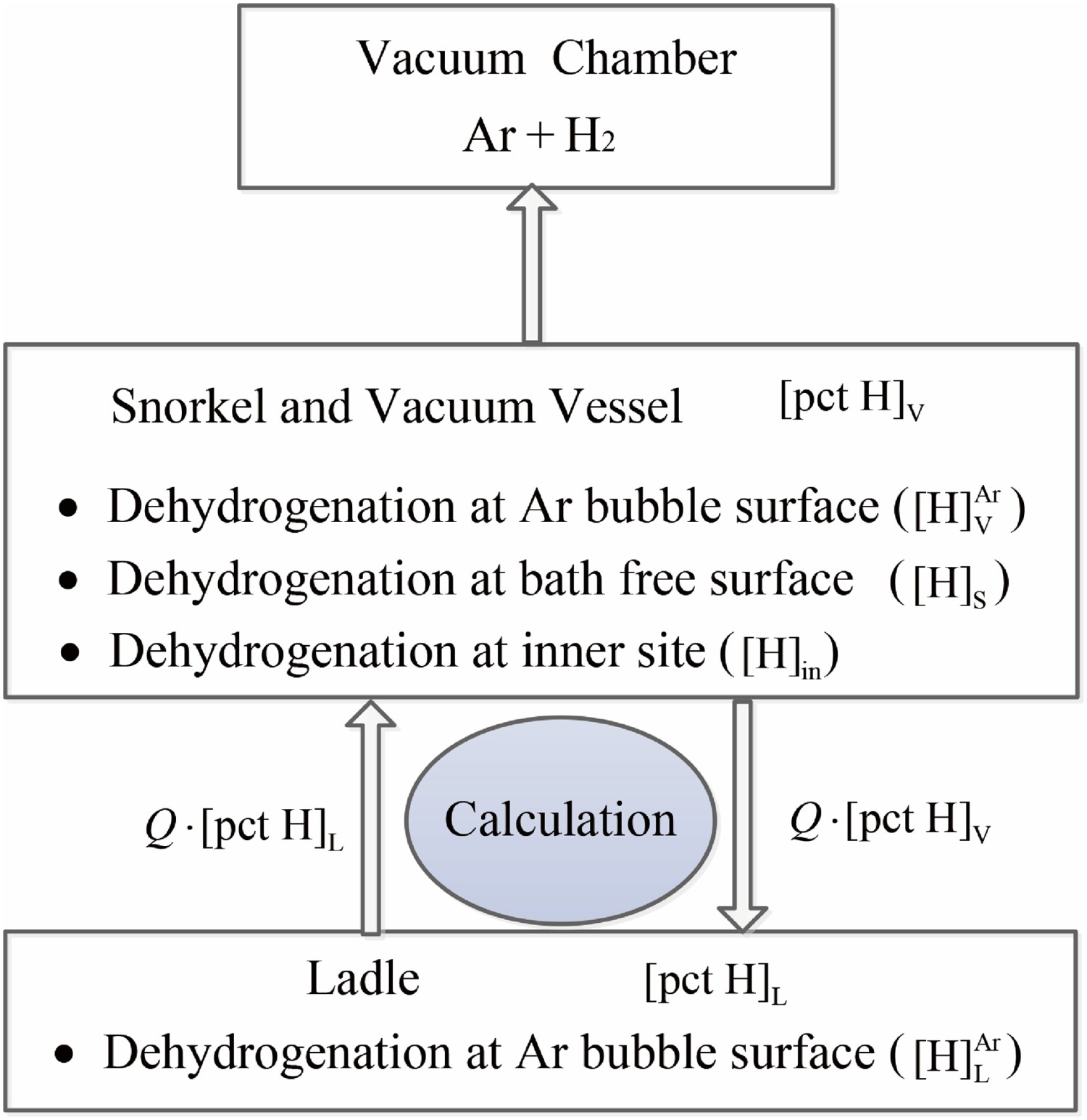
In the present study, it is assumed that dehydrogenation reactions take place at three sites in SSRF: Ar bubble surface, bath surface, and the bulk steel. The schematic diagram of each dehydrogenation site is illustrated in Figure 2. Once Ar gas is injected into the molten steel, Ar bubble surface dehydrogenation occurs when the dissolved hydrogen atoms diffuse to the bubble interface, and the generated H2 gas enters into Ar bubble. The dehydrogenation process proceeds continuously as the bubbles rise from the porous plug to the bath surface. Similarly, bath surface dehydrogenation takes place when dissolved hydrogen atoms combines with each other to generate H2 gas at bath surface, and escapes from the vacuum vessel with Ar bubbles soon. The bath surface is constantly updated due to the gas stirring and vacuum pumping, which is conducive to the dehydrogenation reaction here. In addition, the dehydrogenation reaction in the bulk steel is also considered at low-pressure level, in which a large number of H2 bubbles will be formed near the bath surface. Schematic diagram of three reaction sites for dehydrogenation of SSRF.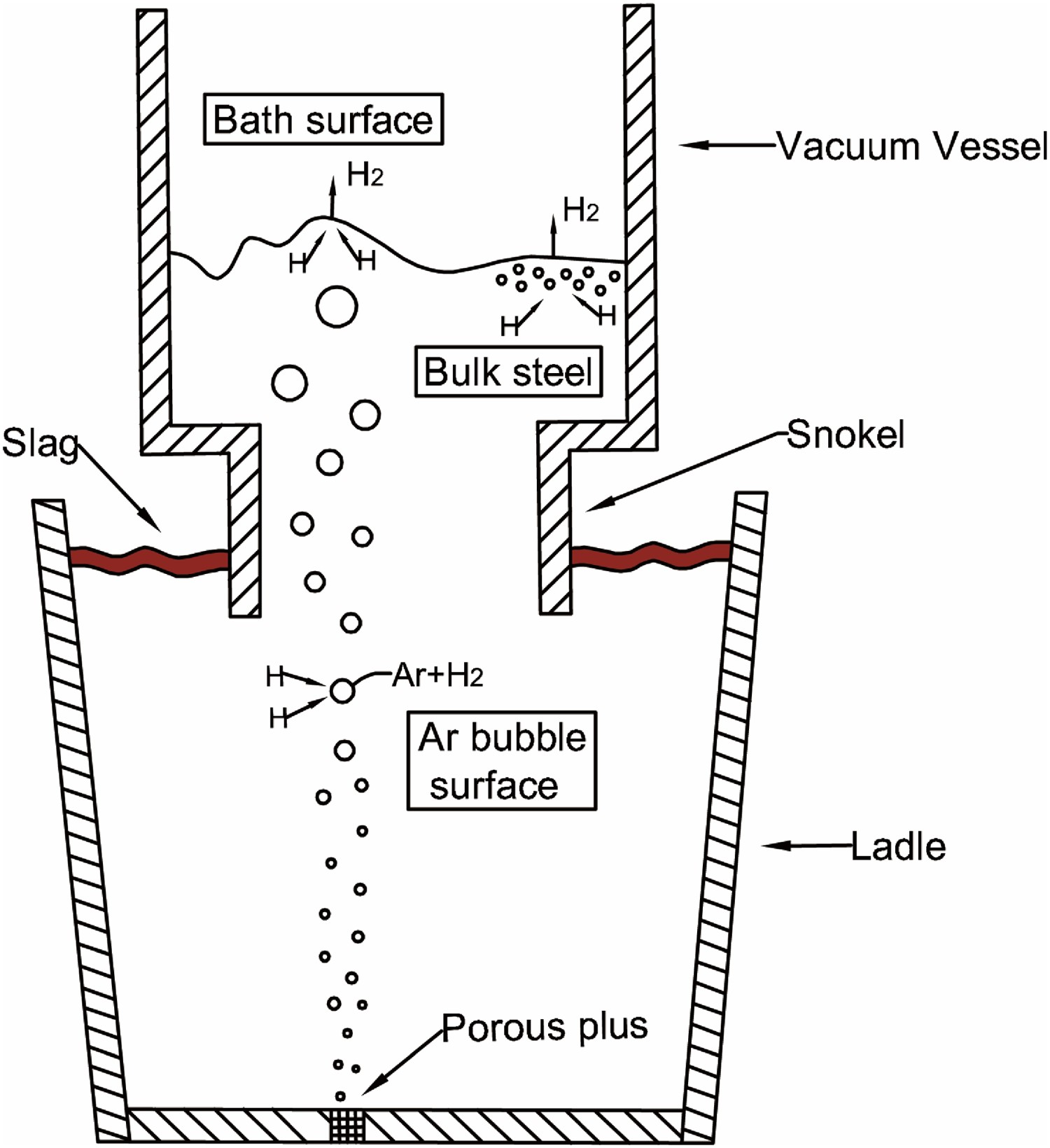
Noticeably, both bath surface dehydrogenation and bulk steel dehydrogenation only occur in the vacuum vessel, while Ar bubble surface dehydrogenation takes place not only in the vacuum vessel but also in the ladle. For the convenience of calculation, the dehydrogenation rates of each reaction site were calculated separately by their respective reaction models, and their sum was taken as the total dehydrogenation rate of SSRF.
Dehydrogenation at Ar bubble surface
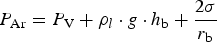
Ar bubble surface is an important reaction site for dehydrogenation in SSRF vacuum refining. Ar bubbles injected from porous plug exist in the form of bubble plume in molten steel and provide a large superficial area for dehydrogenation reaction. Also, low H2 partial pressure in these bubbles significantly can effectively accelerate the dehydrogenation reaction at Ar bubble surface. Here, dehydrogenation process mainly includes the following steps: first, mass transfer of dissolved hydrogen to gas–liquid reaction interface; second, chemical reaction occurs at bubble surface; third, generated H2 gas gets into the gas phase. As pointed out by Ootsuka et al. [15], the mass transfer of dissolved hydrogen (the first step) was regarded as the rate-determining step of Ar bubble surface dehydrogenation. Moreover, Ar bubbles are assumed to spherical and do not coalescence or break when rising in the model.
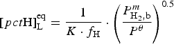
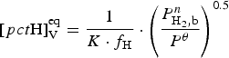
The reaction rate (mass per cent s−1) through Ar bubbles in the ladle is expressed by Equation (4). And the equilibrium hydrogen content at Ar bubble surface in the ladle is calculated by Equation (5)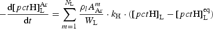


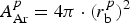

The initial radius of Ar bubble is assumed to be 0.006 m in the model. Figure 3 depicts the variation of Ar bubble radius with height from the porous plus at t=360 s. It can be seen that the Ar bubble size gradually increases from 0.006 to 0.034 m as the bubble ascends from the plug to bath surface. Moreover, the growth rate of Ar bubble in the vacuum vessel is higher than that in the ladle. Variation of r
b with height from the porous plus.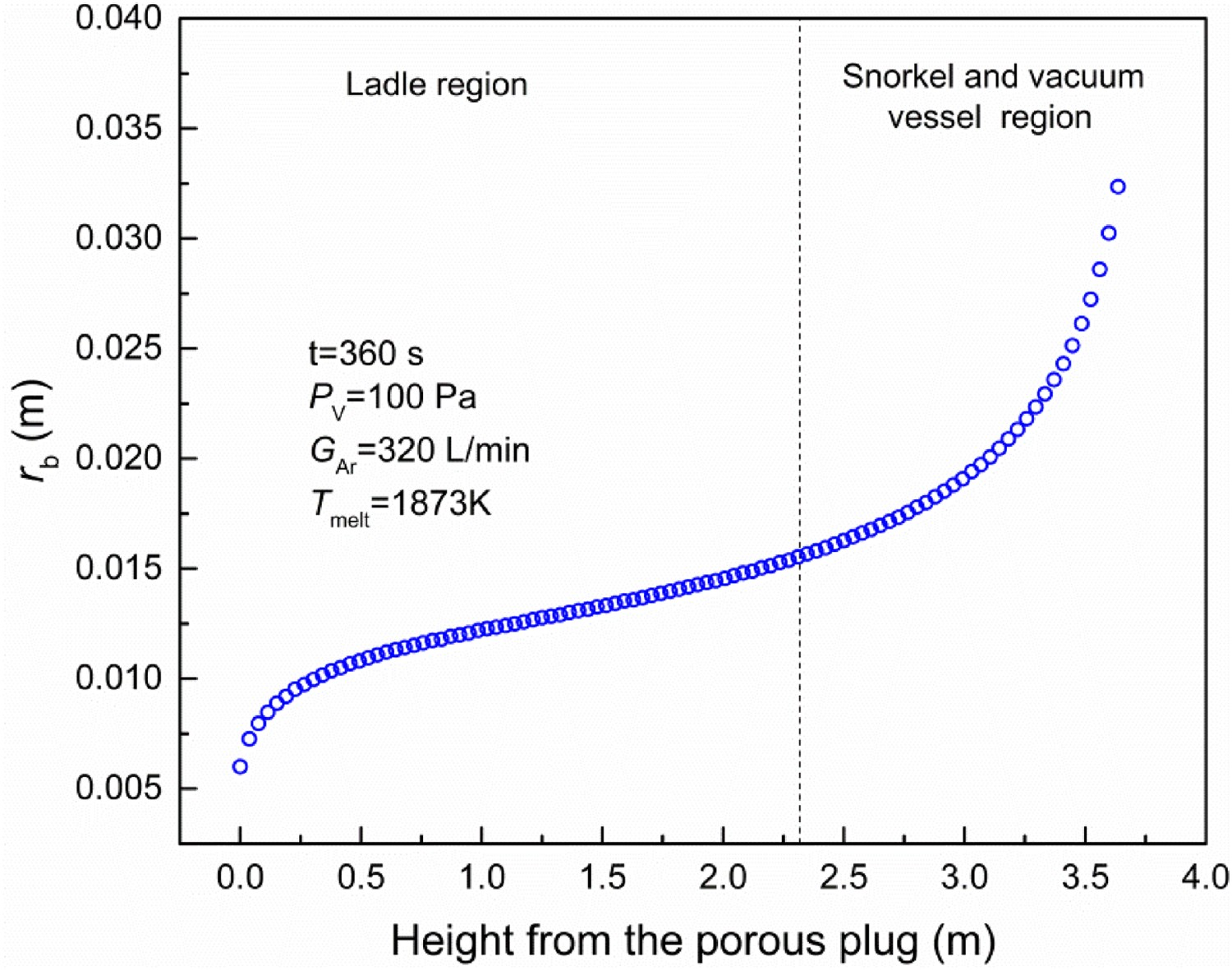
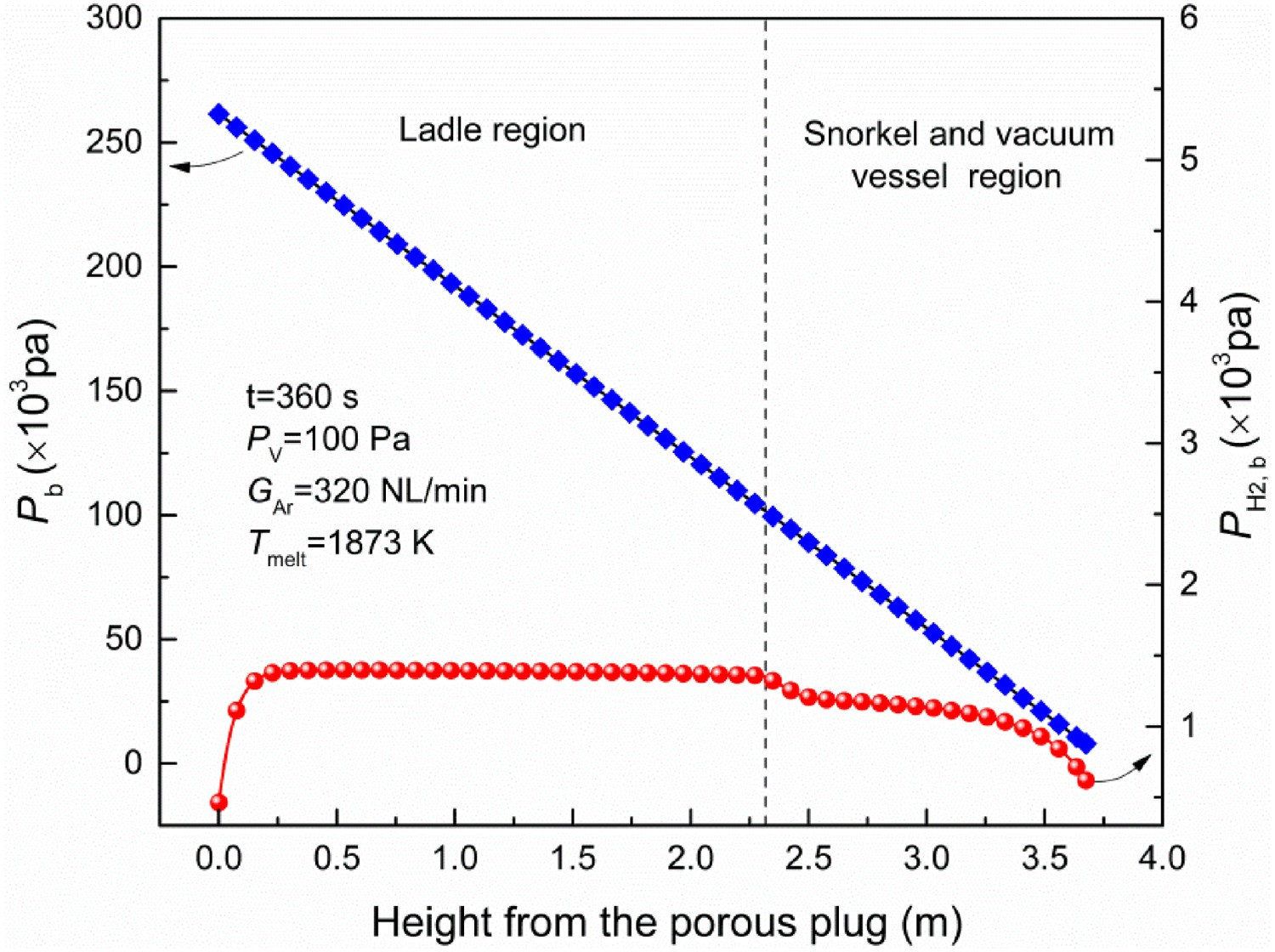
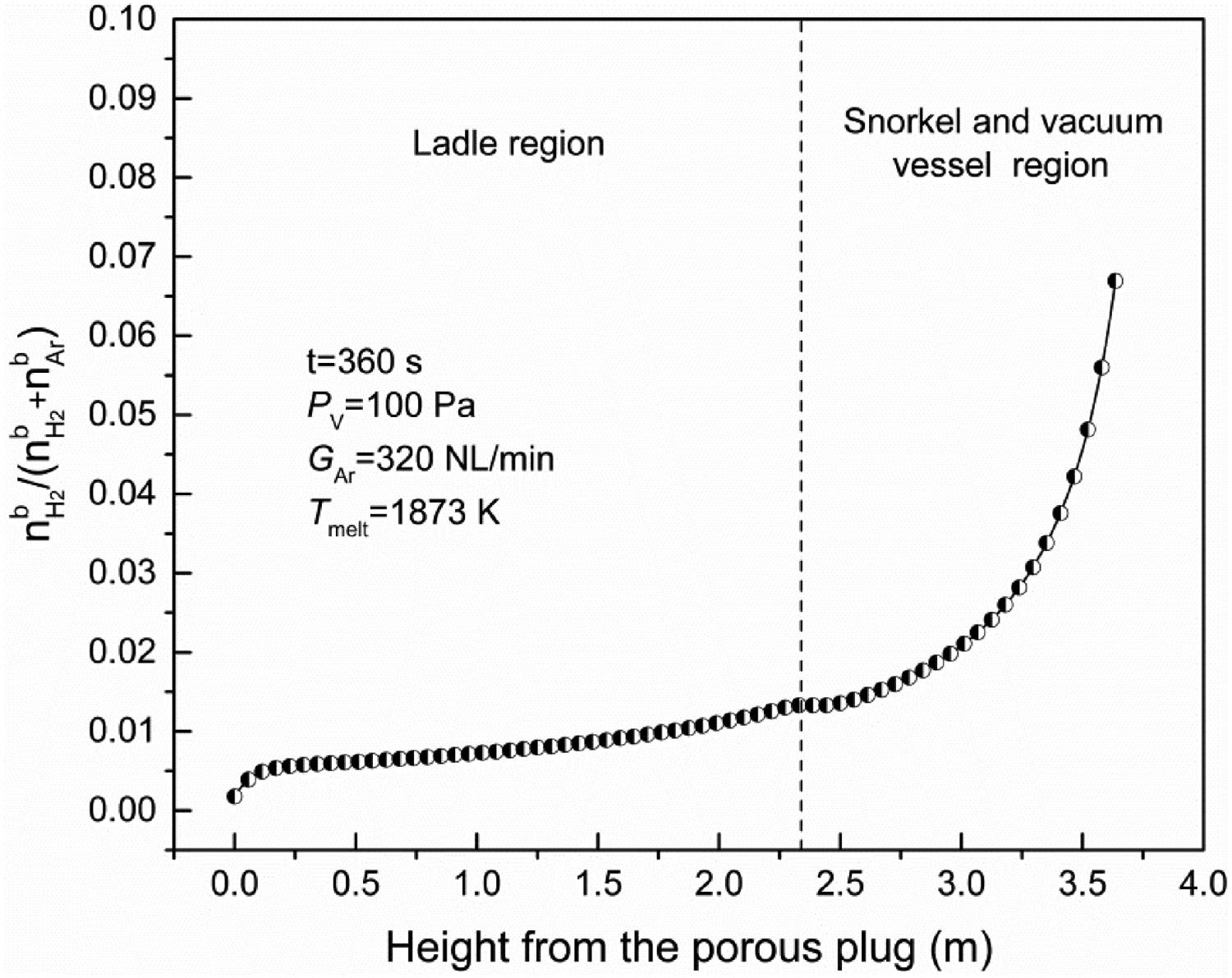
Figures 4 and 5 represent the variation of Variations of P
H2,b, P
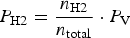
b, with height from the plug. Variations of H2 mole fraction in Ar bubble with height from the plug.


Based on the above calculations, the dehydrogenation rate at Ar bubble surface in the ladle and the vacuum vessel can be obtained. Therefore, the total dehydrogenation rate (kg s−1) at Ar bubble surface is also calculated by the below equation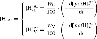
Dehydrogenation at bath surface
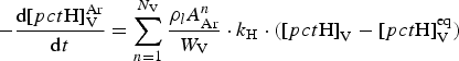
Bath surface represents the contact interface between molten steel and its upper gas phase in the vacuum vessel. It is another important dehydrogenation reaction site. As the dehydrogenation principle at the bath surface is similar to that of Ar bubble surface, the mass transfer of dissolved hydrogen to the reaction interface is considered to be the rate-determining step of dehydrogenation at bath surface. Here, the reaction rate (mass per cent s−1) through the bath surface in the vacuum vessel is expressed by the below equation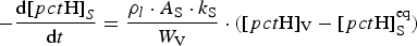
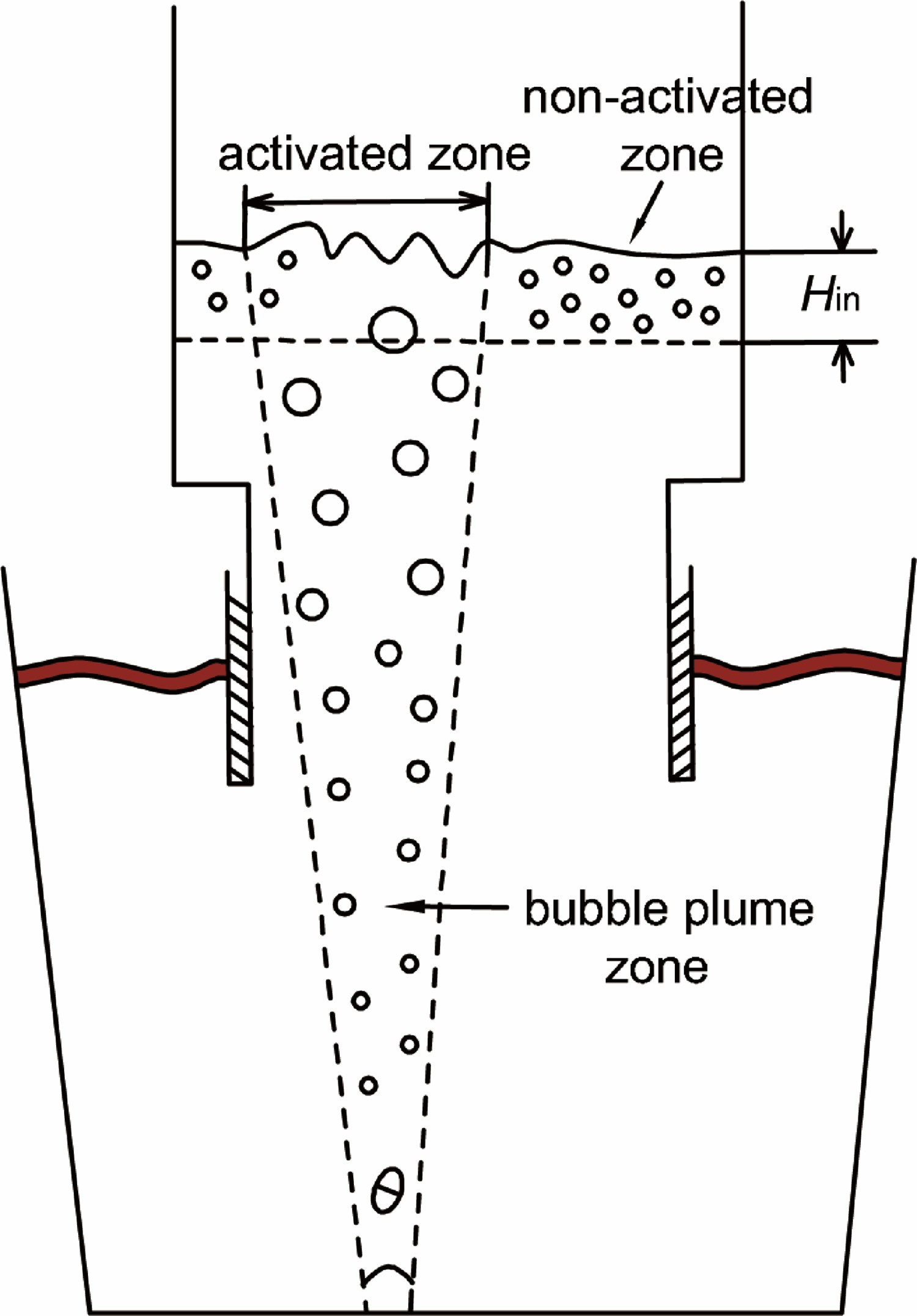
The effective surface area (A
S) can be divided into two sections in the bubble plume region: non-activated zone and activated zone, as shown in Figure 6, which is expressed by the below equation Activated zone and non-activated zone at bath surface of SSRF.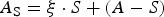


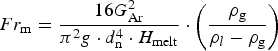
According to Krishna Murthy’s study [31], the angle of gas plume zone (θ) can be estimated by Equation (20), and the modified Froude number is calculated by Equation (21)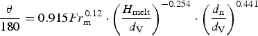

Based on the above calculations, the dehydrogenation rate (kg s−1) at the bath surface in the vacuum vessel is obtained by the below equation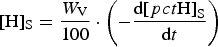
Dehydrogenation in the bulk steel
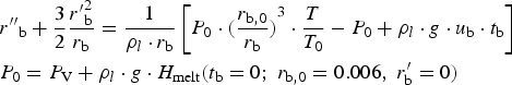
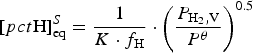
Bulk steel dehydrogenation's first concern is to how H2 gas bubbles nucleate and grow up, because there is no initial reaction surface similar to the bath surface or the Ar bubble surface. According to Ref. [20], the dehydrogenation reaction in the bulk steel is unlikely to occur through the homogeneous nucleation of H2 bubbles in liquid steel system, in which a surprisingly large gas super-saturation pressure of about 104 atm is required. Instead, the H2 bubbles formed on the surface of refractories or granular slag are feasible in energy at a very small super-saturated pressure. Furthermore, it is assumed that H2 bubbles have been generated in the bulk steel, but the minimum pressure in the bubbles should be at least 0.01 atm if the generated H2 gas is to be kept intact in the light of Winkler's study [20]. Therefore, the heterogeneous nucleation of H2 bubbles can only be formed near the bath surface in the vacuum vessel, and the vacuum pressure is regarded as the rate-determining step of dehydrogenation in the bulk steel.
The necessary conditions for H2 nucleation in the bulk steel can be expressed by as follows: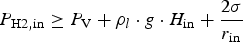

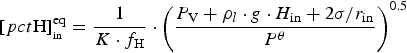
In Equation (25), the integral formula on the right indicates that bulk steel dehydrogenation is a volume reaction within the critical depth (H
in). As the upper limit of the integral formula, H
in should be greater than zero and can be calculated as follows: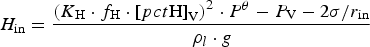

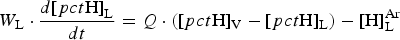
Dehydrogenation process in SSRF
In the SSRF system, the concept of the dehydrogenation process can be described as: the dissolved hydrogen content of the vacuum vessel is different from that of the ladle during the refining period because of the different removal rate between these two regions. However, it is assumed that the distribution of dissolved hydrogen is uniform at the initial stage. With continuous circulation and mixing of molten steel, the difference of hydrogen content between the ladle and the vacuum vessel will not be expanded but remain relatively stable.
The circulation flow rate of molten steel (Q) is one of the key links for the dehydrogenation process, which can be used to reflect the fluidity and uniformity of molten steel. Increasing Q can effectively promote the circulating flow of molten steel and the ability of vacuum degassing. According to an empirical formula [7], Q (kg s−1) is estimated by the below equation Material balance in the dehydrogenation process of SSRF.

Program and computation process
After establishing the sub-models for dehydrogenation reactions that take place at Ar bubble surface, at the bath surface, and in the bulk steel, the mathematical simulation of the dehydrogenation process in 80 ton SSRF is performed in MATLAB 2017b on a personal computer. The calculation program chart of dehydrogenation process during SSRF treatment is shown in Figure 8. Calculation program chart for the dehydrogenation process in SSRF.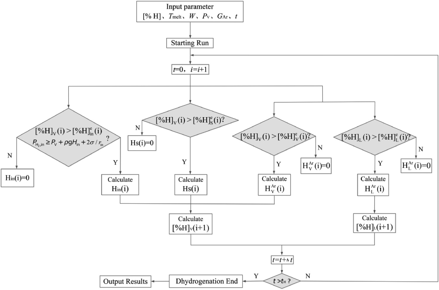
Result and discussion
Model validation
The dehydrogenation reaction was calculated for the 80 ton SSSF process using this mathematical model. The operating conditions of the model are consistent with those of the plant (Shanxi Taigang Stainless Steel Corporation Limited). Figure 9 depicts the variation of the relevant operating parameters (P
V and G
Ar) during the actual industrial conditions. The pressure drops rapidly from atmospheric pressure and then reaches a stable deep vacuum state (usually under 100 Pa). And argon flow rate increased rapidly before the beginning of the deep vacuum pressure and stabilized at 320 NL min−1 after 2 min, which lasted for the remaining period. The hydrogen content in molten steel was sampled by a Hydrogen Reading Immersion System (HYDRIS) probe before and after 18 min degassing. The sampling position was 30 cm below the slag of the ladle. Besides, the temperature of molten steel varies from 1893 to 1833K during 18 min degassing, and the effect of slag on dehydrogenation is ignored. Variation of P
V and G
Ar with time.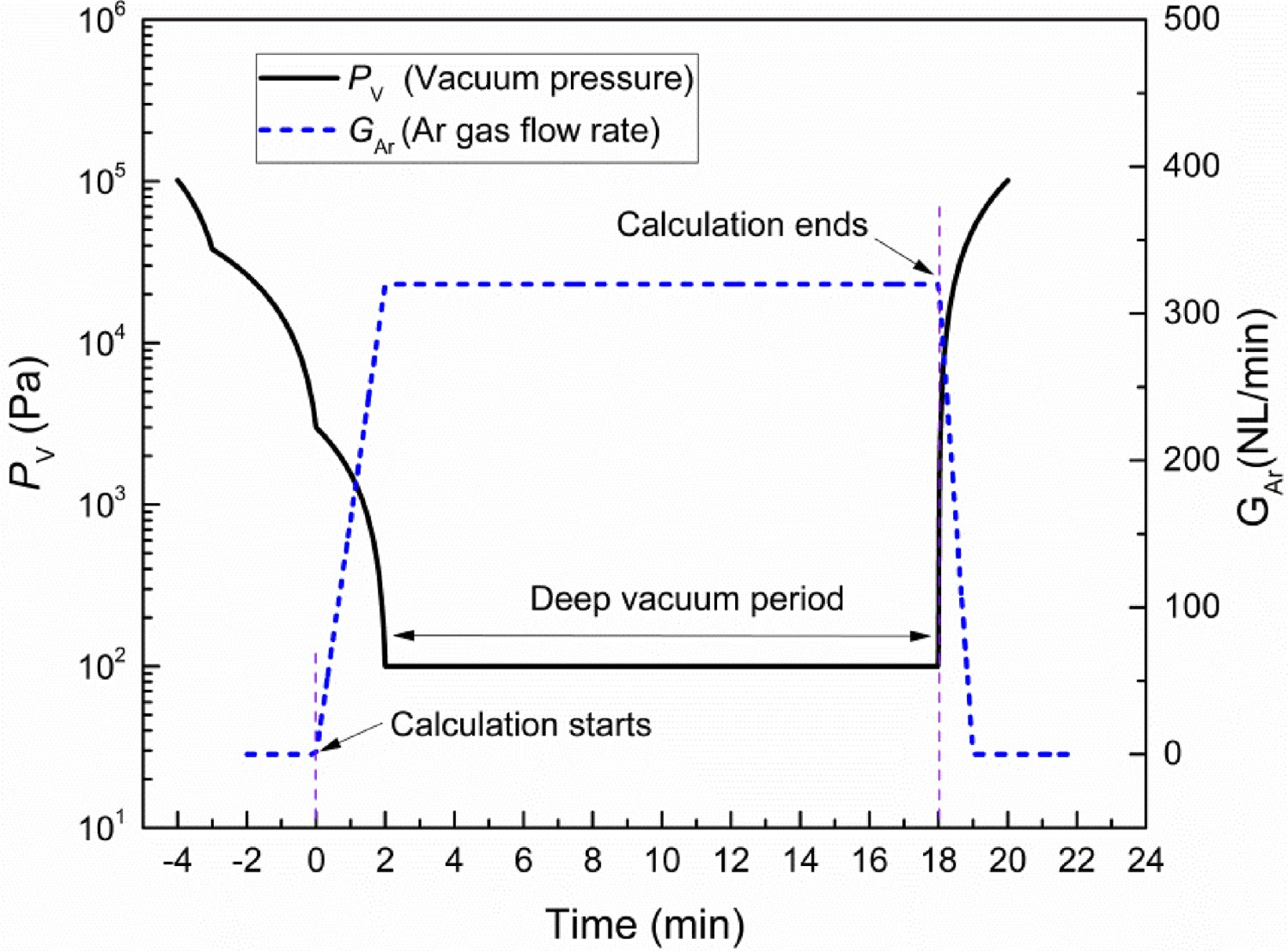
Variations of hydrogen content between calculated and measured values before and after 18 min degassing.
The comparison of calculated and measured hydrogen content before and after 18 min degassing is displayed in Figure 10. The results showed that the measured values lied close to the model predictions, with data points falling within ±0.2 ppm of the 1:1 line, at which the calculated and measured values were exactly equal. Within the allowable error range, the simulation results are in good agreement with actual production data, indicating that dehydrogenation behaviour in SSRF could well explain by the model. Besides, the subtle difference between the two sets of data may be due to the change of weather condition, hydrogen absorption on slag surface, or fluctuation of operating parameters (e.g. gas flow rate) in actual production, which is inevitable. Comparison of calculated and measured final hydrogen content before and after 18 min degassing.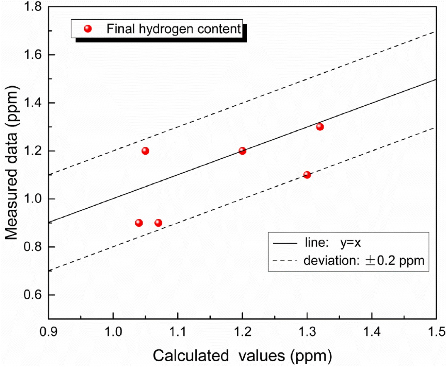
Analysis of SSRF dehydrogenation process
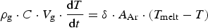
Using the mathematical model, the dehydrogenation behaviour of SSRF during vacuum treatment can be analysed. Figure 11 shows for two example heats, the results show that with the increase in refining time, the variation tendency of dissolved hydrogen concentration first accelerates and then slowed down. It is also found that the initial value of hydrogen has no significant effect on the residual content after vacuum treatment, which is basically consistent with previous work of other steelmaking process [32]. Variations of hydrogen content for heat A and heat B.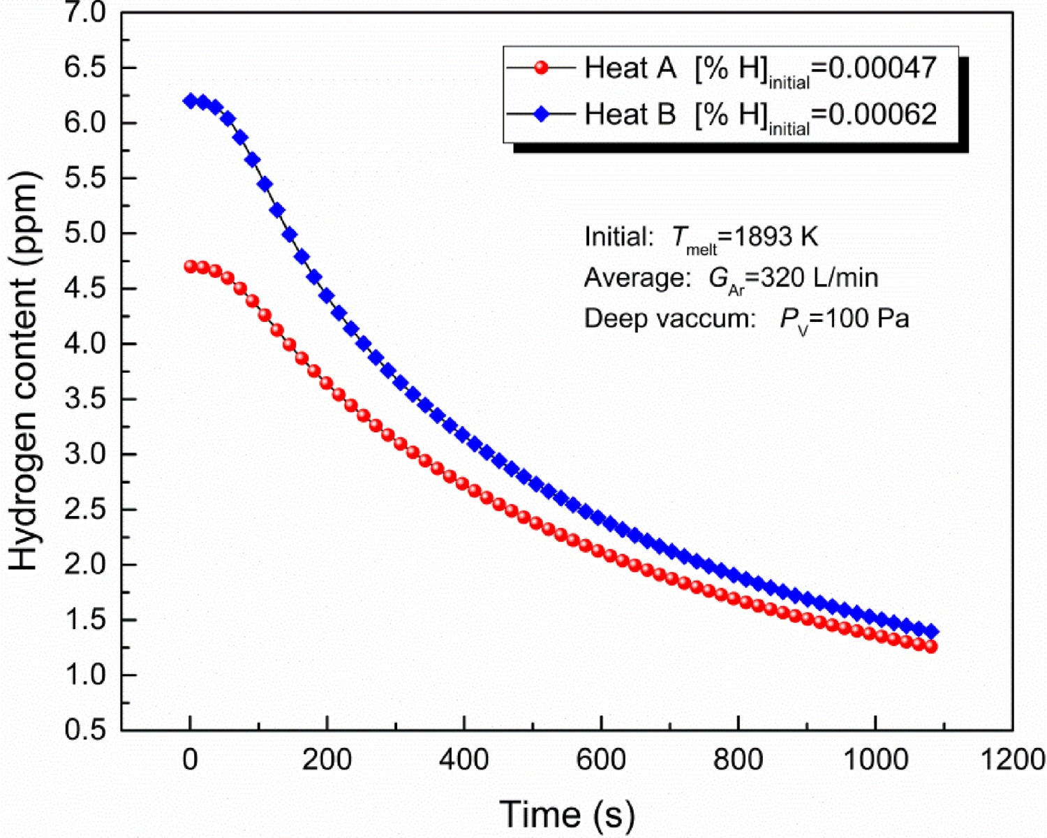
Figure 12 depicts the variations of dehydrogenation rate at each reaction site in heat A. From the beginning to t=120 s, the dehydrogenation rate of Ar bubble surface and bath surface increases rapidly with the increase in argon flow rate, and then decreases gradually. However, the dehydrogenation rate of the bulk steel increases rapidly from zero, and catches up with that of the bath surface at t=60 s and peaks at 1.04×10⁻⁴ kg s−1. Thereafter, the dehydrogenation rate in the bulk steel decreases rapidly and decreases to zero at t=340 s, because of the current vacuum pressure (100 Pa) limiting H2 nucleation in the bulk steel when [pct H]L<0.000295. From t=340 s to the end of SSRF treatment, the dissolved hydrogen concentration is at a low level, and the dehydrogenation reaction mainly takes place at Ar bubble surface and the bath surface. In addition, Ar bubble surface dehydrogenation can be divided into two regions: the ladle and the vacuum vessel, of which the dehydrogenation rates are plotted in Figure 13. Comparing the two curves, the dehydrogenation rate through Ar bubbles in the vacuum vessel is much higher than that in the ladle because of a rapid expansion of Ar bubble after entering the vacuum vessel. Variations of dehydrogenation rate at each site with time. Dehydrogenation rates of Ar bubble surface in ladle and vacuum vessel for heat A.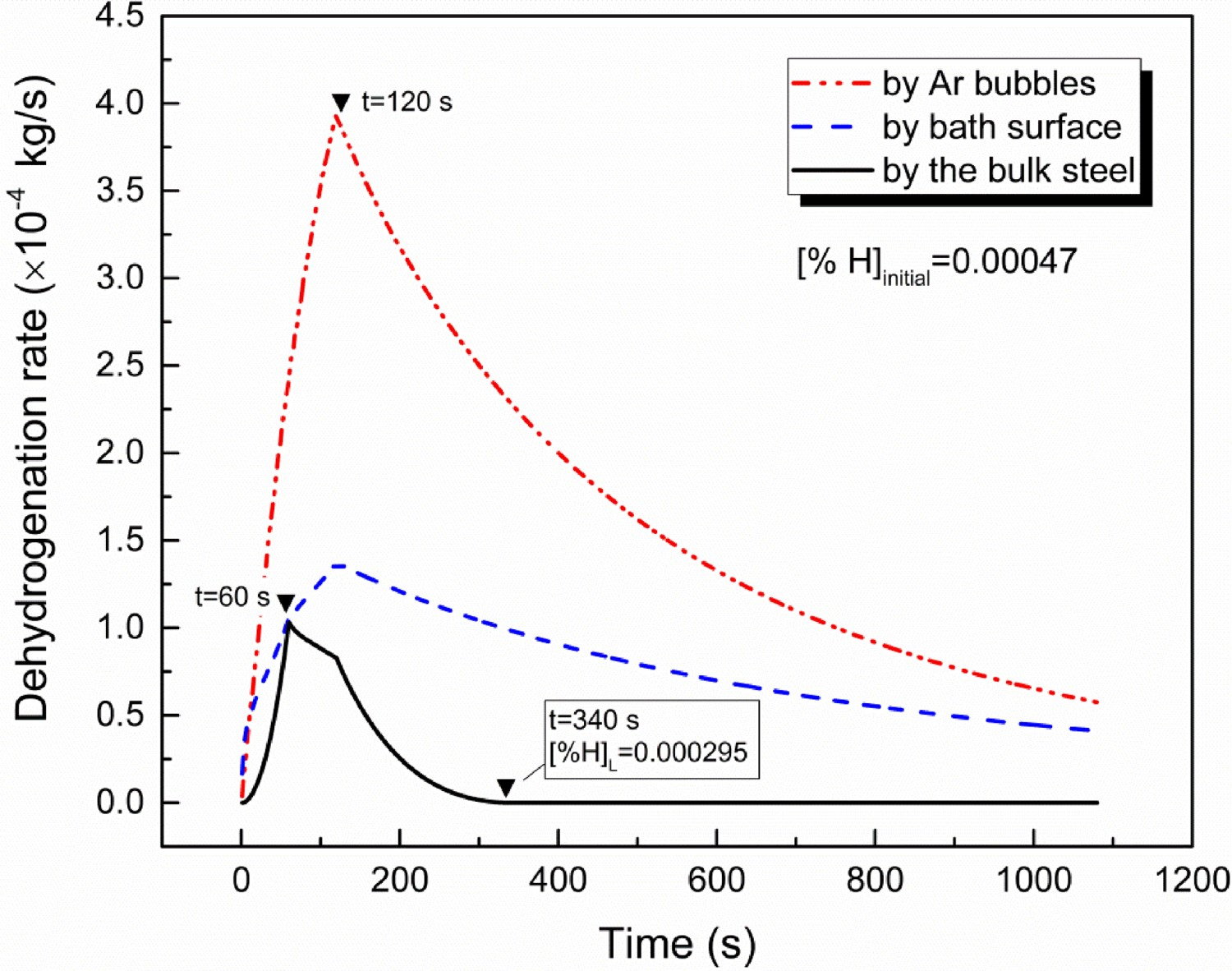
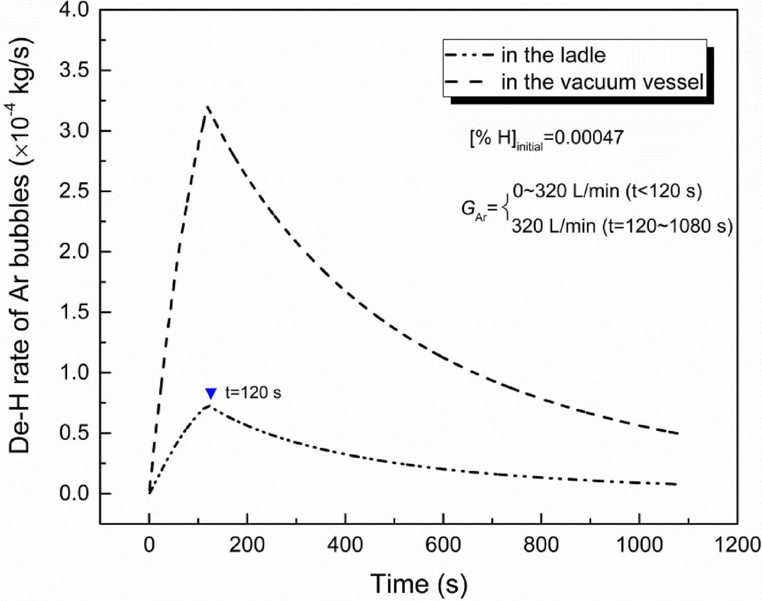
Figure 14 shows the variation of Hin and [H]in with the decrease in [pct H]L in heat B. It can be seen that both of Hin and [H]in increase rapidly from the beginning, reaching to a peak value at t=60 s, and then gradually reduces to zero. This indicates that the variation tendency of Hin and [H]in is basically the same. Besides, there is a platform for Hin with the decrease in [pct H]L from 0.00060 to 0.00053. According to Equation (27), Hin is greatly affected by [pct H]V and P
V. The reason for the transition from the peak to the platform of Hin is that the drop rate of P
V falls behind in that of [pct H]V. Until [pct H]L<0.000294, the H2 nucleation conditions became no longer be satisfied with Equation (24), thus the dehydrogenation reaction in the bulk steel would be too difficult to continue in SSRF. Variations of Hin and [H]in in with time for heat B.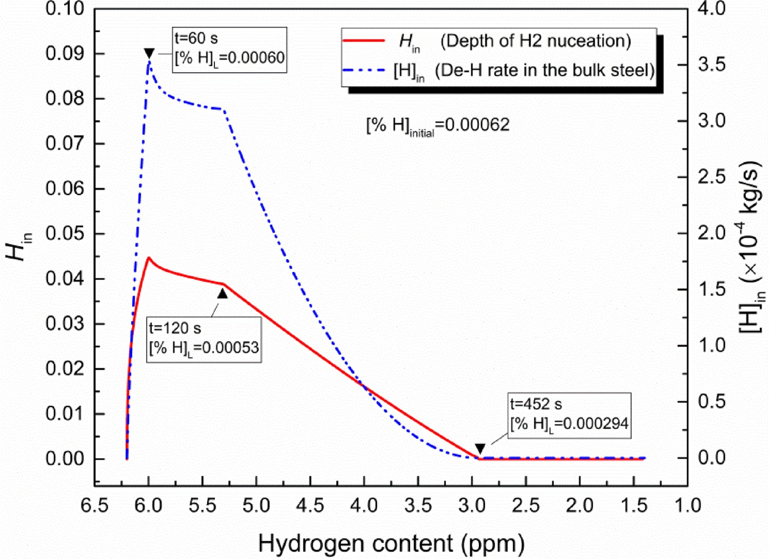
Figure 15 depicts the contributions of each dehydrogenation rate to the total dehydrogenation rate. It can be seen that the contribution of dehydrogenation at Ar bubble surface far exceeds those of the bulk steel and bath surface, and accounting for over 60 pct of total removal accumulation. The contribution of bulk steel dehydrogenation increases rapidly from the beginning, and slides into a decreasing after reaching the maximum mass percentage of 16.9 pct at t=88 s. Instead, the contribution of bath surface dehydrogenation is inversely proportional that of the bulk steel. At the end degassing, the dehydrogenation amount of Ar bubbles accounted for the highest proportion (∼65 pct) of the total, and that of bath surface was about 30 pct, while that of the bulk molten steel is the least, only about 5 pct. Percentage of accumulated dehydrogenation rate at each site for heat A.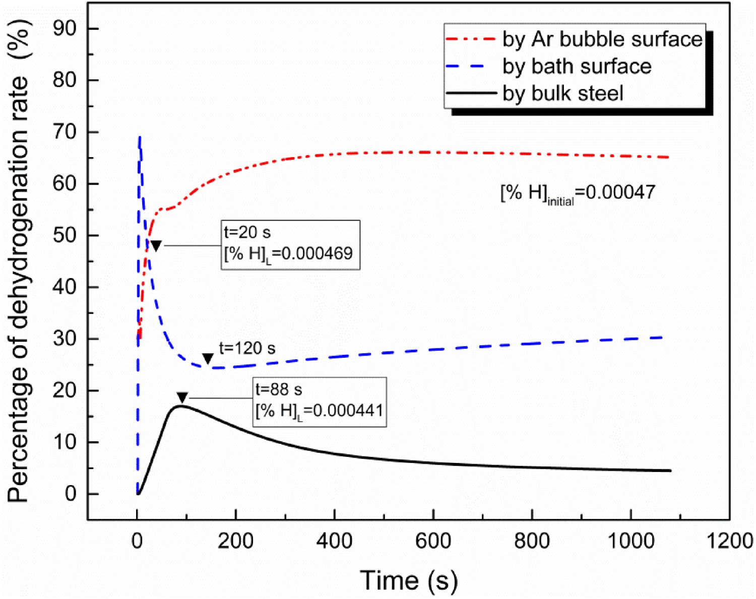
In overall, the reactions of Ar bubble surface and bath surface play a dominant role in the whole dehydrogenation process of SSRF. Compared with their contribution, dehydrogenation through heterogeneous nucleation of H2 bubbles in the bulk steel contributes little to the dehydrogenation process. It only occurs in the range of high hydrogen content (or early stage of dehydrogenation).
As mentioned before, increasing argon flow rate cannot only expand the total surface area of Ar bubbles and activated area of bath surface (as shown in Figure 6), but also accelerate the mass transfer of dissolved hydrogen to their reaction interface through enhancing the circulating flow rate. Thus, the effect of the argon flow rate on the dehydrogenation of SSRF was investigated. As shown in Figure 16, the hydrogen level before vacuum degassing has 4.7 ppm values which gets reduced to 0.9–2.3 ppm after vacuum degassing during 18 min degassing at constant pressure. And the operating condition to achieve hydrogen level <1.2 ppm was satisfied with the argon flow rate of 320–400 NL min−1. Furthermore, an excessive argon flow rate can improve the dehydrogenation efficiency of SSRF, but it might lead to the corrosion of the snorkel refractory as well as the increase in argon cost. Variations of hydrogen content under different argon flow rate.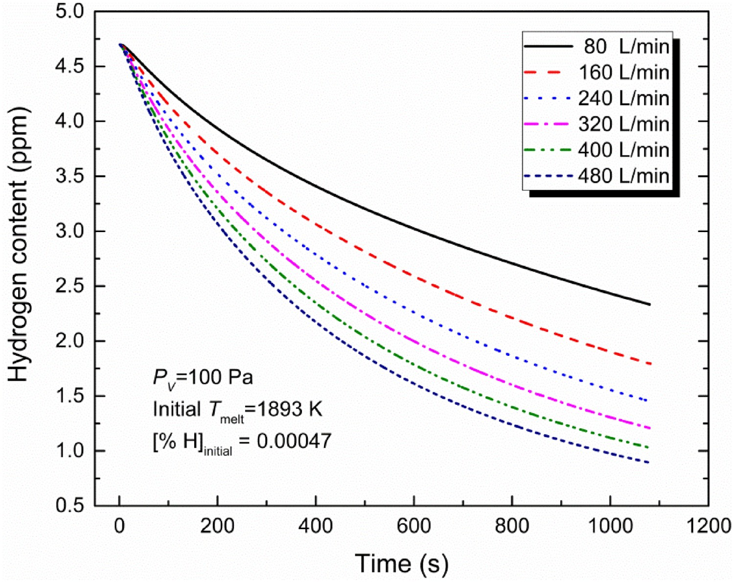
Conclusion
In the present study, the dehydrogenation model that take place at Ar bubble surface, bath surface, and the bulk steel is developed to investigate the dehydrogenation behaviour in SSRF vacuum treatment. The calculated results were compared with the industrial measured data. And the contribution of hydrogen removal at three sites and the effect of argon flow rate on its removal efficiency were studied. The conclusions are as follows: The predicted results of the final hydrogen content of six heats are in good agreement with the experimental results (the deviation <0.2 ppm). Hence, the dehydrogenation behaviour in an industrial SSRF can be well explained using the present model. Both Ar bubble surface dehydrogenation and bath surface dehydrogenation are involved in the whole refining period. However, bulk steel dehydrogenation only occurred in the range of high hydrogen concentration (or early stage), which would stop once the dissolved hydrogen content dropped below 2.95 ppm. Throughout the dehydrogenation process, the contribution rate of Ar bubble surface dehydrogenation is the largest, about 65%, that of bath surface dehydrogenation is 30%, while the contribution rate of bulk steel dehydrogenation is only 5%. The dehydrogenation efficiency of SSRF can be significantly improved by increasing argon flow rate. Under the argon flow rate of 320–400 NL min−1, the hydrogen level got reduced to <1.2 ppm after vacuum treatment for 18 min. Additionally, an excessive argon flow rate is not desirable, because it might cause the corrosion of the snorkel refractory as well as the increase in argon cost.
Footnotes
Acknowledgements
The authors would like to thank the National Natural Science Foundation of China (grant number 51674024, 51874034) for the financial support.
Disclosure statement
No potential conflict of interest was reported by the author(s).