
Abstract
Springback plays a key role in the geometrical and dimensional integrity of the product obtained in metal forming. This study investigated the formability of high-strength complex phase CP800 sheet under V-bending at room temperature. The experiments were carried out on 2.5-mm-thick material using parameters of four different bending angles, three different punch radii and two different holding times. The effects of selected parameters on springback were investigated both experimentally and via finite element analysis (FEA). As a result of the study, it was determined that the amount of springback decreased as the die angle (α) increased and increased as the punch radius (r) increased, and that the effect of the holding time remained limited. In addition, the damage was observed in the bending samples obtained under experimental conditions of α = 60° and r = 2 mm. The experimental and simulation findings showed that the measured angles (β) were in good agreement (>95%).
Introduction
Recently, significant developments have been achieved in the materials used by the automotive industry in terms of reducing CO2 emissions, weight, and fuel consumption and of increasing passenger safety [1–3]. In general, formability and ductility decrease with increasing strength. However, multi-phase high-strength steels exhibit an excellent combination of strength and ductility [4]. Multi-phase high-strength steels can absorb much more energy than conventional steels with the same amount of deformation before uniform elongation [5,6]. This feature is an indication that they have a better crash performance than conventional steels. Among the multi-phase steels that have become increasingly common lately are the complex phase (CP) steels. These CP steels have a complex phase microstructure consisting of fine-grained ferrite, bainite and some martensite [7]. With low hardness rates, CP steels show high local formability on the one hand, while on the other hand, they exhibit weak global formability caused by the higher dislocation density as an effect of the harder phases [8]. Although high-strength steel sheets are very attractive in various applications, they also have the disadvantage of springback. The amount of springback is very high in formed high-strength steel sheets because of their high strength [9]. The springback that occurs after forming the sheet materials causes the desired shape of the final designed product to be distorted. This creates problems with quality and difficulties in assembly. This dimensional problem caused by springback is a function of the elastic stress that occurs during the shaping of the parts [10,11].
Zhang et al. [1] conducted a study on the forming performance of seven 800 MPa strength complex phase steels. They applied tensile, hole expansion and HAT shape stamping tests to these steels. They reported that the maximum springback angle was obtained when the pressure plate forces for the CP800 steel rose from 50 to 100 kN, and that the springback angle decreased for the pressure plate forces of 150 and 200 kN. Furthermore, Zhang et al. [4] conducted another study investigating the springback behaviour of S700MC, CP800S, CP800T and CP800 steels. They carried out HAT shape stamping tests to determine the springback behaviour of the steels. They found that CP800 steel demonstrated the lowest springback behaviour, and that springback was reduced as the pressure plate force was increased.
As a result of these studies, it was determined that not enough research has been carried out on the forming of CP high-strength sheet via the bending method. On the other hand, since the multi-phase microstructure of such steels causes complex micromechanical behaviour, it is necessary to investigate the formability of these steels using various forming methods that enable their use in different sectors, especially in the automotive industry.
This study investigated the springback behaviour of CP800 complex phase steel after the V-bending process, both experimentally and via the finite element method (FEM). For springback measurements, 24 different experiments were carried out and the amount of springback formed after the experiments was measured using a coordinate measuring machine (CMM). Finite element analysis (FEA) was performed using the Simufact Forming program.
Material and methods
Commercially available CP800 sheet was used in the study. The thickness of the sheet used in the experiments was t = 2.5 mm and bending samples were prepared in the dimensions of 40 × 40 mm. Experiments were carried out at room temperature and the rolling direction. The chemical composition of the material is given in Table 1 and its mechanical properties in Table 2. The microstructural composition of CP800 steel can be seen in Table 3, and Table 4 gives the test parameters and their values. The Simufact Forming finite element software was used in the study. A compatibility rate of 90% for both the experimental and FEA results could be achieved only by transferring the material properties used in the real experiments to the FEA environment. Therefore, when defining the material in the FEA environment, the stress–strain curves used were obtained from the experimental material in the real environment. The die, punch and sheet were designed in three dimensions (Figure 1) and the analyses were carried out in three dimensions. The parameters used in the FEA are given in Table 5 and the die model is shown in Figure 1. Finite element model of V-bending process. Chemical composition of CP800 steel (%). Mechanical properties of CP800 steel. Microstructural composition of CP800 steel [8]. *Bainite or tempered martensite; both phases are indistinguishable via EBSD measurements. Experimental study parameters. FEA simulation parameters.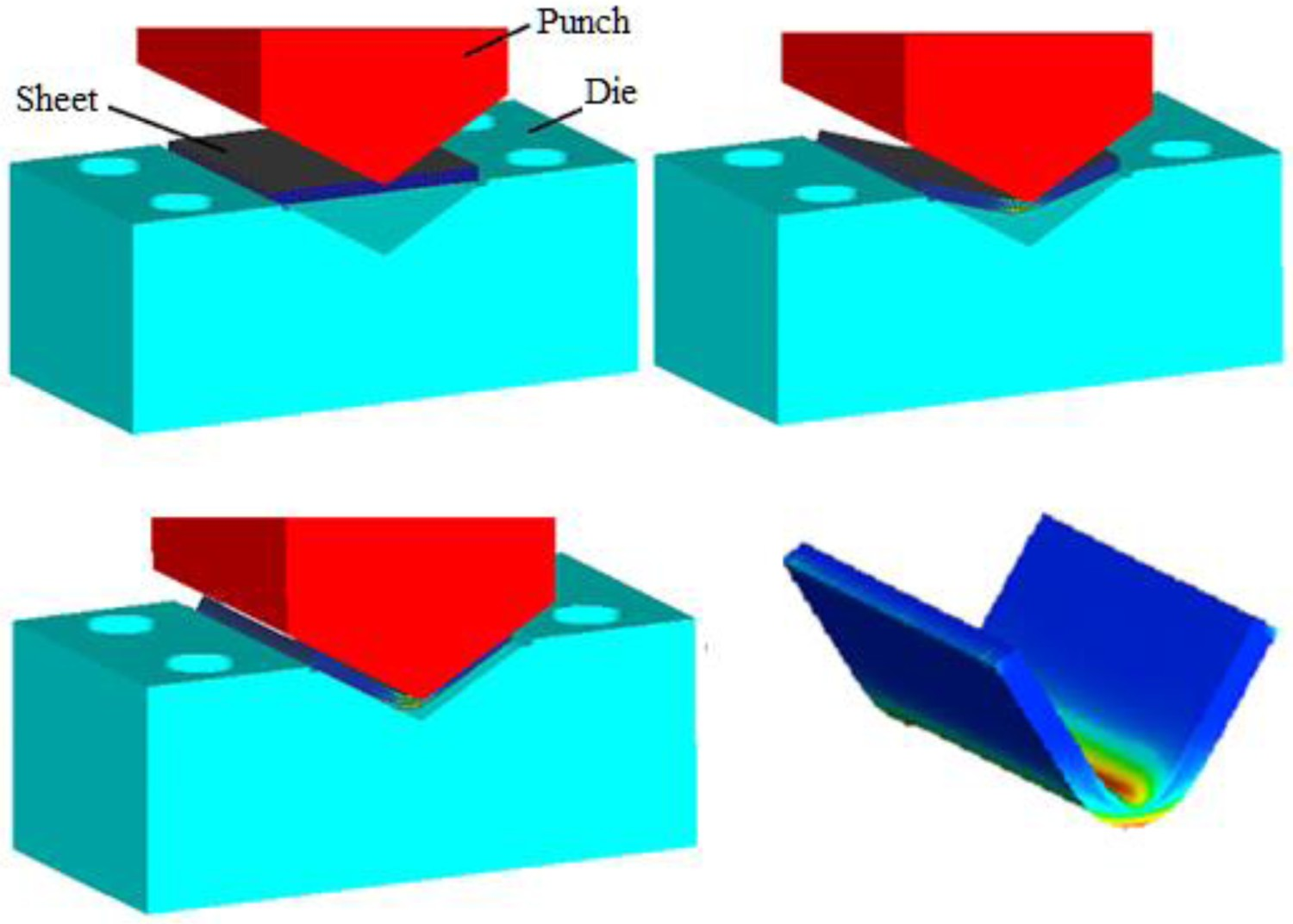
The punch speed was kept at 10 mm s−1 and the holding force was 2 tons (19.61 kN). When the holding force reached 19.61 kN, the punch withdrew, after waiting for the duration of the holding time. The period when the punch is held on the bent sheet metal after pressing is called the holding time. At the end of the forming process, two different holding times were determined (0 and 10 s).
In order to determine the effects of different die angles, four different die angles (60°, 90°, 120° and 150°) were used, with 2, 4 and 6 mm punch radii for each angle. Schematic representations of the experimental setup and the V-bending dies are given in Figure 2. V-bending test setup and bending dies.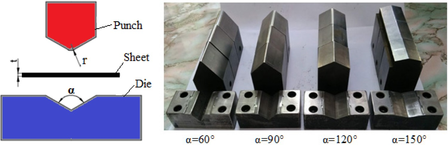
A total of 24 experiments were carried out within the scope of the study. Upon completion of the experiments, the springback values of each part were measured using the Hexagon Coordinate Measurement Machine (CMM) (Figure 3). Schematic view of springback and measurement with the CMM: (a) measuring process, (b) measuring points on both surfaces, (c) springback angle.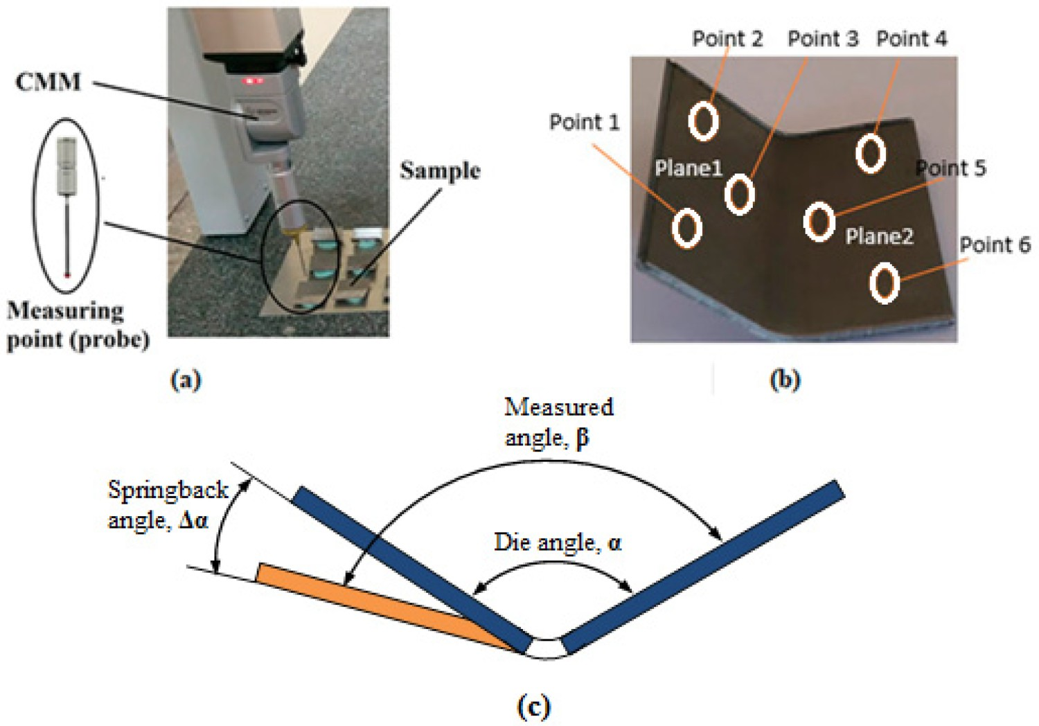
Results and discussion
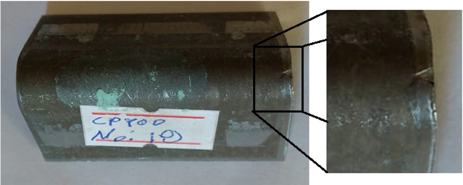
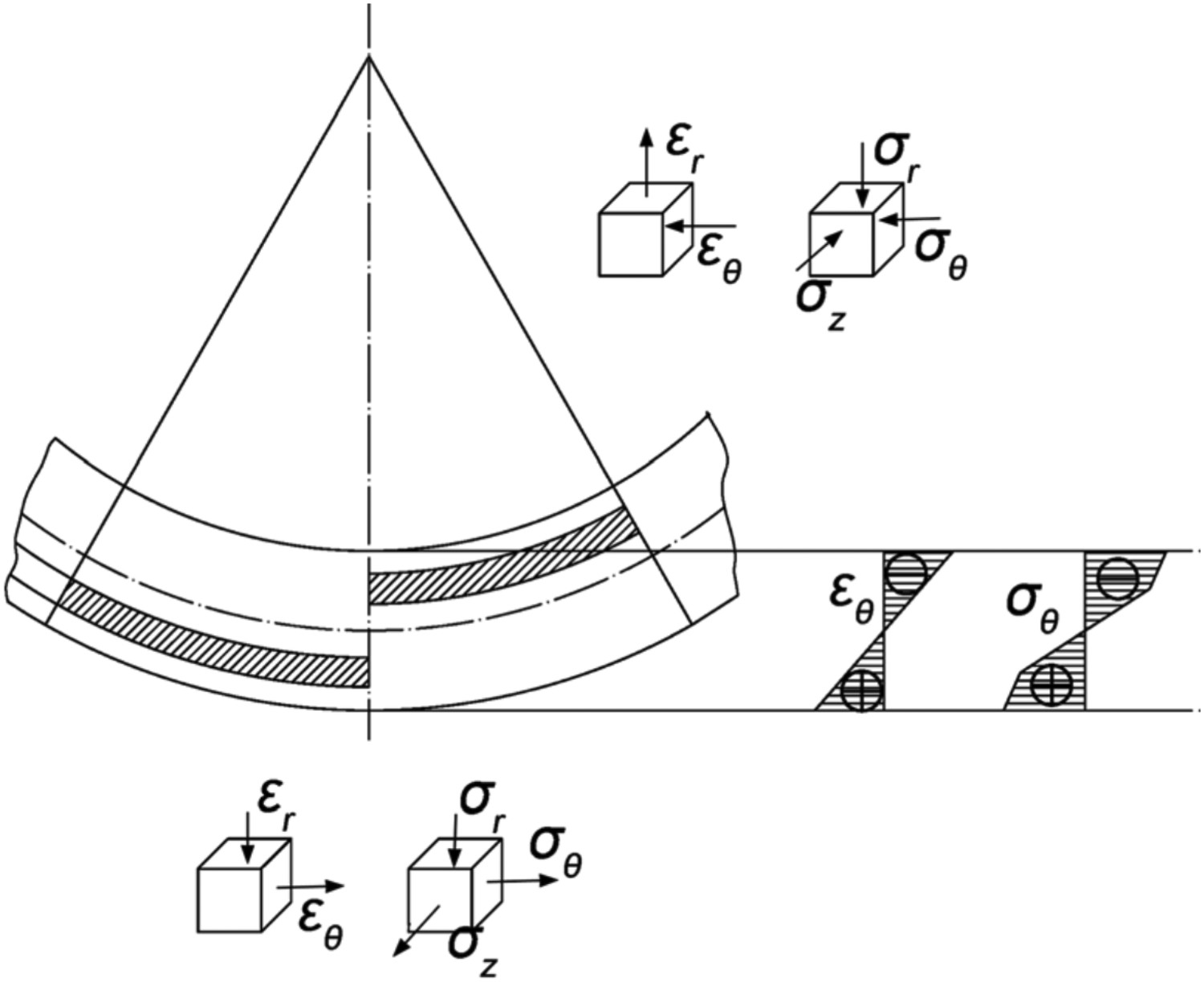
The results obtained from the experiments and analyses within the scope of the study are given in Table 6, and an image of the parts shaped as a result of the experiments is given in Figure 4. Figure 5 shows a damaged sample after bending. Damage occurred only in parts bent under α = 60° die angle and r = 2 mm punch radius. The small die angle and the small punch radius caused an excessive increase of stress in the bending zone. In the bending process, the sheet material undergoes plastic deformation during forming. During the deformation, compressive stresses occur on the inner surface of the sheet material where it comes in contact with the punch, whereas tensile stress occurs on the outer surface of the sheet material [12]. After the punch movement is completed and a balance is achieved between the stresses on the inner and outer surface of the sheet, the deformation is also completed. The springback that occurs after bending is related to the magnitude of the distribution of the bending moment. Tensile and compressive stresses in the bending region play an important role in this [13]. During bending, as shown in Figure 6, the inner and outer layers of the bending zone are under compression and tension, respectively. Since the material flows along the tangential direction, the tangential stress (σθ
), radial stress (σr
) and transverse stress (σz
) in the inner and outer layers are much larger, while the tangential strain (ϵθ
) is much larger than the radial strain (ϵr
). The transverse strain is neglected because the width/thickness ratio is very large [14]. Shaped parts after bending. Part damaged under experimental conditions of α = 60° and r = 2 mm. Distribution of stress and strain in the bending zone during bending [14]. Experimental sets and results.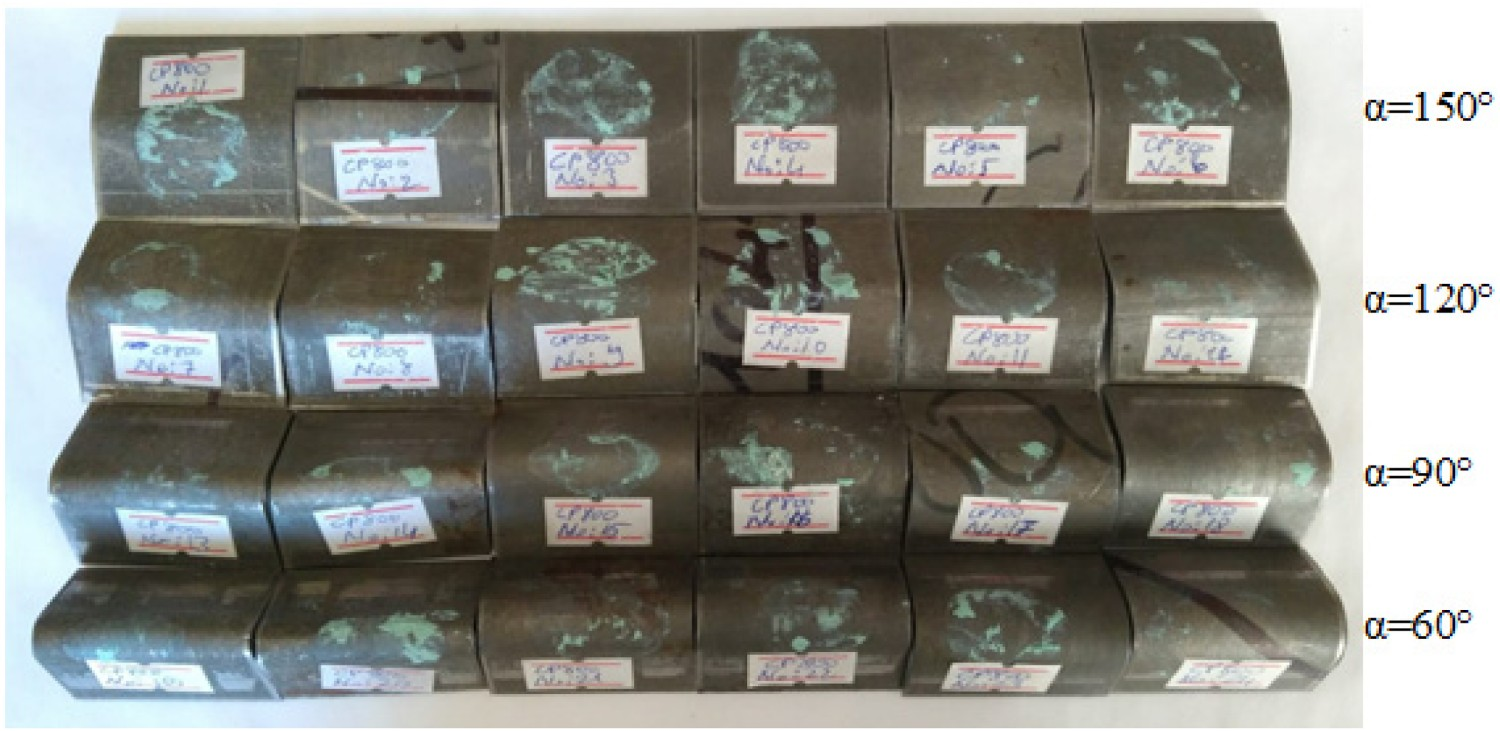
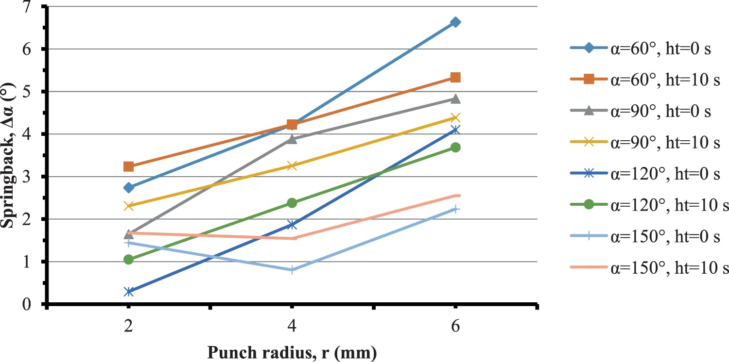
Springback is a result of the elastic return of the formed material. Figure 7 shows the effect of the angle of the die on springback. When the figure is analysed, it can be seen that as the die angle increases, the springback decreases, which also means that as the die angle decreases, the tension increases, and accordingly, springback also increases. This case can be explained by the increase of bending moment in the bending zone, which is compatible with the findings of other studies [15]. Several researchers [16–18] have stated that the springback of sheet material is associated with tangential stresses. Looking again at the studies [19–22], an increase in holding time is shown to reduce the elastic return of the material, thus reducing the springback. In the present study, it was useful to consider the effect of holding time together with punch radius and die angle. When the punch radius was 2 mm it was also seen that springback increased for all bending angles with an increase in holding time. With the punch radius increased to 4 mm when holding time was increased from 0 to 10 s, springback increased for the bending processes at 120° and 150°, while it decreased for 60° and 90°. With the punch radius of 6 mm, the springback decreased for all bending angles when holding time was increased. The effect of holding time on springback is better understood from the increases in die angle and punch radius. In the study, within the scope of this information, the lowest springback (Δα = 0.295°) was obtained under the conditions of r = 2 mm (punch radius), ht = 0 s (holding time) and α = 120° (bending angle), whereas the greatest springback (Δα = 6.633°) was found with r = 6 mm, ht = 0 s and α = 60°. The effect of the punch radius on springback is given in Figure 8, in which it can be seen that as the punch radius increased, the springback value also increased. The springback depends on the size of the plastic deformation zone. A punch with a small radius concentrates the pressure force within a narrow space, resulting in higher local stress and more plastic deformation. As the punch radius increases, the force spreads to a large plastic area, thus increasing the springback [23]. In other words, as the punch radius increases, the contact angle and contact area increase. This creates more friction surface between the punch and the sheet. Variations of the springback–die angle relationship. Variations of the springback–punch radius relationship.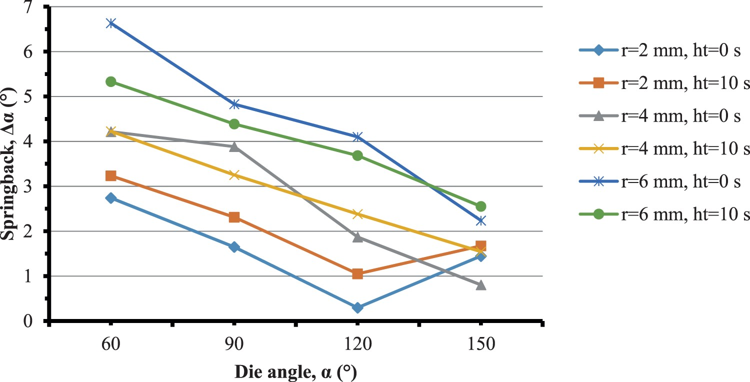
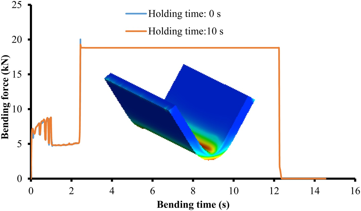
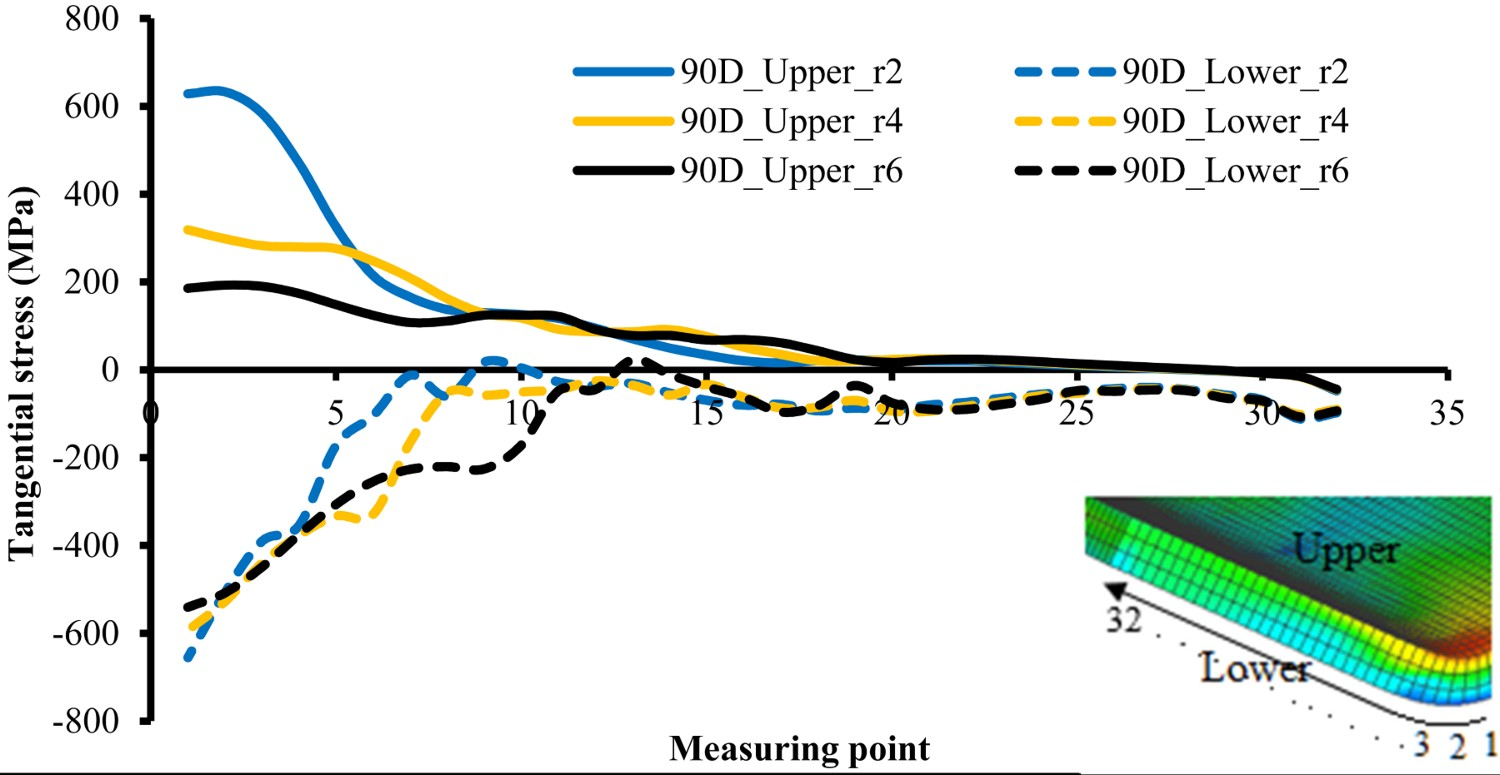
A comparison of the results obtained from the experiments and the simulations is given in Figure 9. It can be said that the results are in good agreement. These results are indications that FEA results can be used in experimental designs if the material properties and test conditions are correctly defined. The bending force depending on holding time generated during the analyses is given in Figure 10. The relationship between holding time and bending force given in Figure 10 was kept constant for all experimental conditions. With no holding time, the bending was completed in 2.443 s, while the bending was completed in 14.538 s with a 10 s holding time. The relationship between the punch radius and tangential stresses is given in Figure 11, which shows that the tension is greatest in the area of the punch radius. It can be said that the local tension decreases as the punch radius increases. A small punch radius causes more local deformation and local stress in the bending zone, thus reducing springback [24]. During full surface contact, as the punch radius increases, the pressure force spreads over a wider area and the tension decreases. As the punch radius increases, ‘t/(2r + t)’ causes less tangential stress in the outer surface layer [14]. Comparison of simulation and experimental springback angle results. Variations of the holding time–bending force relationship. Variations of the tangential stress–punch radius relationship.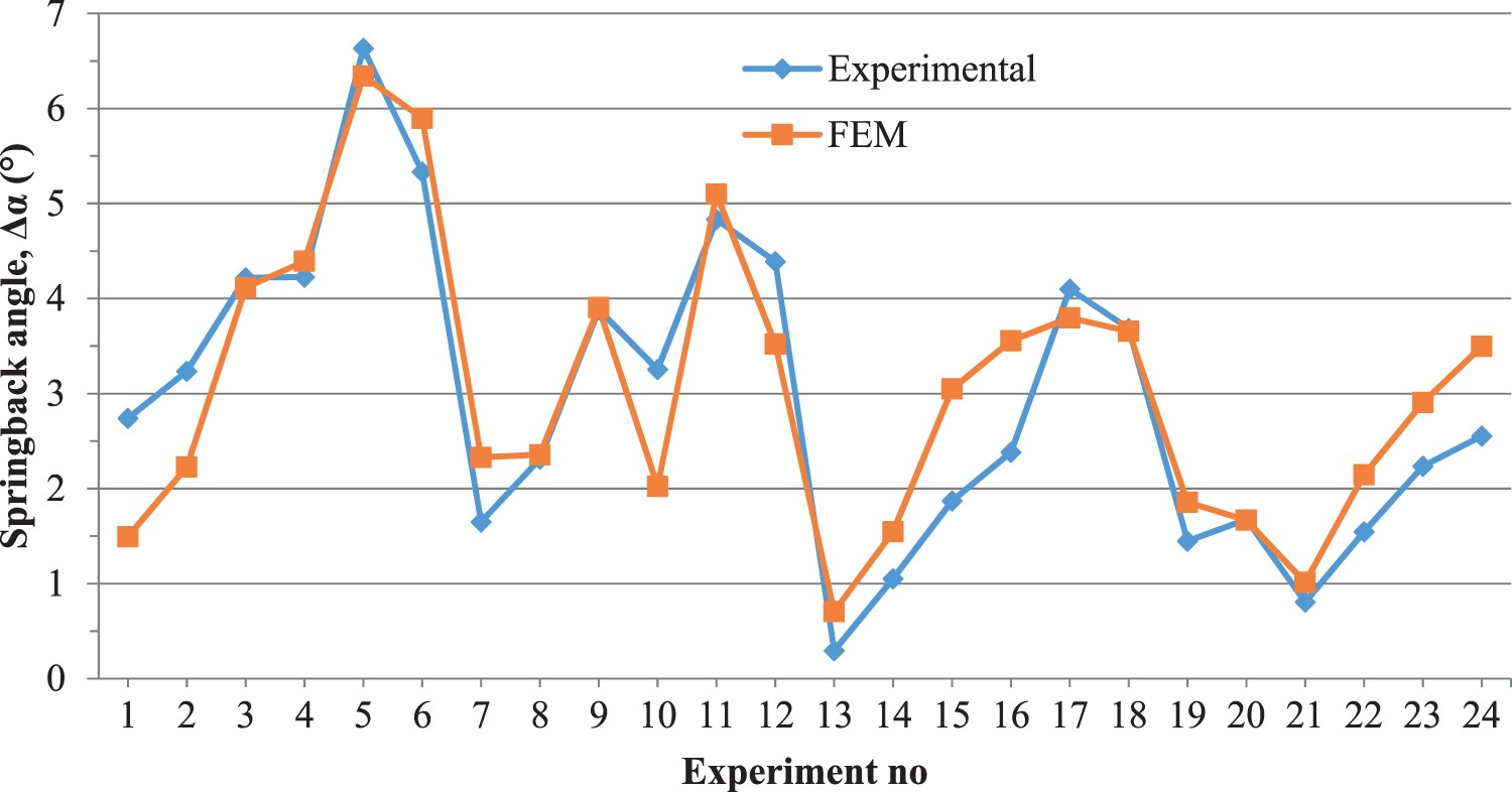
Conclusion
In this study, the results obtained after the forming of high-strength complex phase CP800 sheet by applying V-bending at room temperature are given below. As the die angle increased, the bending moment decreased in the bending zone, which reduced springback. The greatest local deformation and related stress occurred in the region of the small punch radius. As the punch radius increased, tangential stresses decreased, but were spread over a larger area. The increase in local stress and deformation resulting from the small die angle (α = 60°) and small punch radius (r = 2 mm) led to the damage. When the holding time was increased from 0 to 10 s, springback varied depending on the die angle and punch radius. However, it would be useful to apply different longer times in order to better understand the effect of holding time on the forming of such complex-structured steel. It was observed that the experimental results and those of the FEA exhibited a very good agreement. This is very important for enabling the use of FEA results directly in designs. Within the scope of the study, the least springback (Δα = 0.295°) was found under conditions of r = 2 mm (punch radius), t = 0 s (holding time) and α = 120° (bending angle); the greatest springback (Δα = 6.633°) was seen under conditions of r = 6 mm, ht = 0 s and α = 60°. Knowledge of the forming behaviour of steels that have such a complex microstructure can be expanded by increasing the number of parameters.