
Abstract
The morphology of eutectic carbide was studied by application of a transverse static magnetic field (TSMF) during the directional solidification of M2 high-speed steel. The results show that the morphology of eutectic carbide changed from lamella to fibre as the magnetic flux density (MFD) increased from 0 to 1 T. The transformation from lamella to fibre has been enhanced by the increasing MFD. Solute elements moved and gathered at a certain region in the mushy zone when imposing a TSMF. In the mushy zones, channel segregations were formed in the samples treated by 0.2 and 0.4 T TSMF. When the MFD increased to 0.8 and 1 T, the channel segregation disappeared. Morphology transition, solute elements movement and formation of channel segregation were attributed to the thermoelectric magnetic force (TEMF). This work provides a new method to control the distribution of carbides in steel assisted by TEMF.
Introduction
M2 high-speed steel, which is an essential material for metal cutting-tool applications, usually exhibit a high microhardness and outstanding wear and heat resistance [1,2]. In general, their excellent properties are closely associated with the quantity, morphology, and spatial distribution of carbides in the tempered microstructure [3,4]. Numerous studies [5–8] indicate that fibrous eutectic carbides (FECs) lead to significant properties enhancement of M2 high-speed steels. Since FECs feature the poor thermal stability and are easily to be decomposed and refined during the heat treatment process. This has been demonstrated to be benefit for improving their strength and toughness. However, owing to high concentration of carbide forming elements that existed in high-speed steels, the massive large-size fishbone-like eutectic carbides and especially lamellar eutectic carbides (LECs), are much easily precipitated rather than FECs during the solidification process [5,9]. Moreover, LECs are difficult to be broken into carbides with small dimensions through traditional ways, such as forging and heat treatment. They will be preserved in the matrix of steels and seriously deteriorate the performance of steels due to their worse splitting effect on the matrix [10,11].
At present, the widespread approach is increasing the cooling rate during the solidification process. It is reported that the FECs could be solidified successfully by the iron mold casting, given its much higher cooling rate than that of the sand casting [6,7]. Based on the fundamental of high cooling rate, there are many other methods, such as fusible metal mold casting and continuous casting [12,13], were applied to obtain the FECs. However, only lamellar carbides were formed at a low cooling rate [6,7,13,14]. Wight et al. [15–17] reported that powder metallurgy was an efficient way to improve the microstructures of M2 high-speed steel. Besides, previous studies [18,19] show that the movement of the solute elements can be effectively controlled by applying a proper transverse static magnetic field (TSMF) during the directional and even bulk solidification processes. As a result, the morphologies of solidified microstructures for binary Al–Cu [18], Al–Si [20] and Zn–Bi [19] alloys were modified. These are attributed to the formation of thermoelectric magnetic convection (TEMC) which was induced by the thermoelectric magnetic force (TEMF).
The present paper reports a new method to process M2 high-speed steel with FECs distributed in the matrix through imposing a TSMF during the directional solidification at a low cooling rate. Owing to the existence of TEMF, FECs almost occupied the whole section of the sample treated by a 1 T TSMF and channel segregation appeared in the samples treated by 0.2 and 0.4 T TSMF. The mechanism about the effects of TEMF on the morphology transition of eutectic carbides from lamellar to fibre is discussed.
Experimental details
Chemical composition of M2 high-speed steel (wt-%).
The schematic of the experimental facilities is presented in Figure 1(a). The temperature gradient of the vacuum directional solidification furnace was measured to be 5.57°C mm−1 and the cooling rate was calculated to be 0.01114°C s−1 when the withdrawal speed was 2 μm s−1. The cooling rate is quite slow compared to the previous works [6,7,13]. Generally, the directionally solidified sample consists of three parts: a quenching zone, a mushy zone, and a directional solidification zone (Figure 1(b)). The sample was then cut into three parts. One was used for the investigation of the morphology transition of eutectic carbides in the mushy zone in the longitudinal section marked as part I. One was used for the carbides extraction experiments marked as part II. The other one, which was marked as part I in Figure 1(b), was used for the investigation of the morphology transition of eutectic carbides in the directionally solidified zone in the transverse section. (a) Schematic diagram of the experimental equipment, (b) schematic diagram of the sample showing the observation regions, and (c) electrolytic extraction device.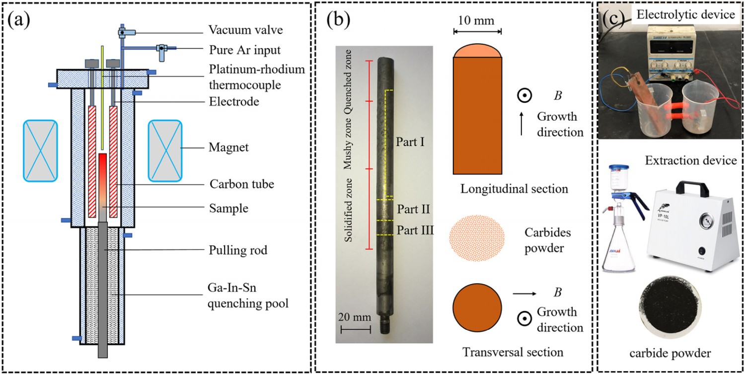
The macro/microstructures were observed by optical microscopy (AXIO IMAGER A2M). The sample is deeply etched by HF+H2O2 for three-dimensional observation of eutectic carbides morphologies. Then, the etched samples were observed by using a scanning electron microscopy (VEGA3 SBH-Easyprobe, TESCAN). The directionally solidified ingots are electrolysed for 40 h in an electrolyte with current density of 0.025 A cm−2, the electrolyte consists of 3% ferrous sulfatel, 1% sodium chloride and 1% tartaric acid. After the end of the electrolysis, the electrolyte of the anode is collected and filtered with a filter having a pore size of 45 μm to extract carbide powder. The electrolytic extraction device is shown in Figure 1(c). The type of the extracted eutectic carbides was examined by XRD (D8 Advance, Bruker AXS).
Results
Macro/microstructures
The macro/microstructures on the transverse sections (part III) of directionally solidified M2 high-speed steels without and with a TSMF are shown in Figure 2. Figure 2(a–f) are the macrostructures. Figure 2(a1–f1) are the microstructures in the upper parts of the transverse sections with LECs. Figure 2(a2–f2) are the microstructures in the lower parts with FECs. After being deeply etched, the morphologies of the primary eutectic carbides in the matrix are magnified in the inserted red dashed squares. Figure 2(a) shows that the LECs are uniformly distributed in the whole transverse section. It is deduced that the morphology of the carbides in the ingot directionally solidified without a TSMF was completely lamella. If a TSMF was applied during the directional solidification, FECs appeared and their distribution area increased gradually with the increase of magnetic flux density (MFD) (Figure 2(b–f), (b1–f1) and (b2–f2)). However, when the MFD was 0.4 T (Figure 2(c)), the distribution area of FECs is larger than that when the MFD was 0.6 T (Figure 2(d)). For the sample treated by a 1 T TSMF, the FECs almost completely occupied the whole transverse section (Figure 2(f)). It is known that the macro/microstructures depend on the evolution of the mushy zone during the directional solidification. Thus, the evolution of the mushy zone needs to be further investigated. Macro/microstructure on the cross-section of M2 high-speed steel directionally solidified with and without a magnetic field. (a) 0 T, (b) 0.2 T, (c) 0.4 T, (d) 0.6 T, (e) 0.8 T, and (f) 1 T. Figure 2(a1–f1) and (a2–f2) are the microstructures in the upper parts and the lower parts of the transverse sections, respectively. The red dashed curves are boundaries of LECs and FECs.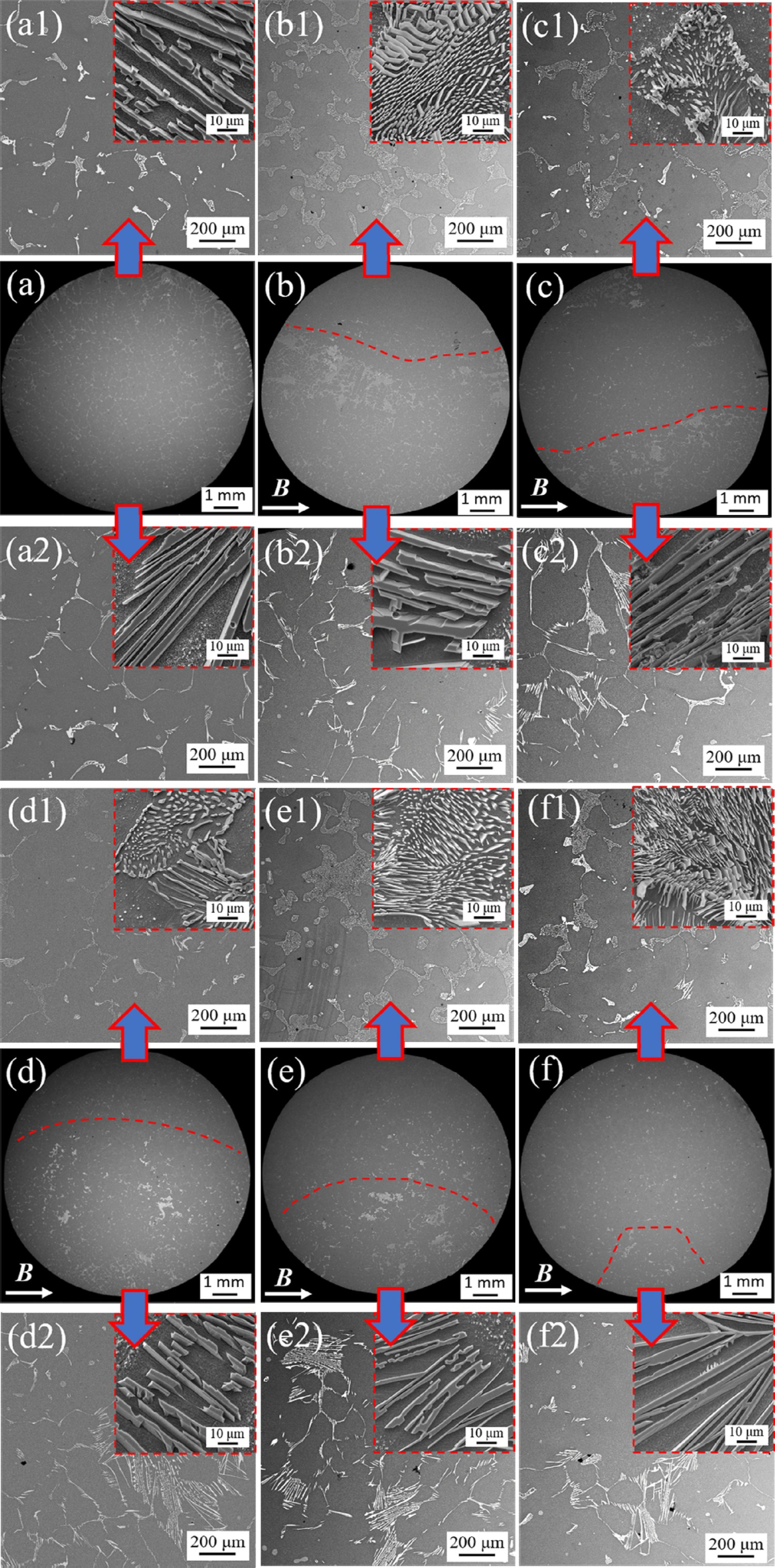
The mushy zones in the longitudinal sections for the samples treated by various MFD are shown in Figure 3. Figure 3(a–f) are the macrostructures. It can be seen that the mushy region is mainly composed of dendrites when the MFD is 0 T. When the MFDs are 0.2 and 0.4 T, channel segregations occur. While the MFD increased to 0.6 and 0.8 T, segregation channel disappears. Figure 3(a1,a2) are the morphologies of eutectic carbides in the yellow dashed square in Figure 3(a). Figure 3(b1–f1) and (b2–f2) are the morphologies of LECs and FECs in the yellow and green dashed square respectively in Figure 3(b–f). These indicate that different morphological eutectic carbides will grow in the mushy regions of different morphologies. In the case of 0 T, LECs uniformly distribute in the radial direction of the sample. In the case of 0.2 and 0.4 T, the left side mainly consists of alternating distribution of FECs and LECs. This is consistent with the distribution of segregation channels. When the MFDs are 0.6, 0.8, and 1 T, the left side is mainly FECs and its distribution area increases with the increase of MFD. Macro/microstructure on the longitudinal structure of M2 high-speed steel directionally solidified with and without a magnetic field: (a) 0 T, (b) 0.2 T, (c) 0.4 T, (d) 0.6 T, (e) 0.8 T, and (f) 1 T; a1 and a2 are LECs, 0 T; b1 and b2 are LECs and FECs, respectively, 0.2 T; c1 and c2 are LECs and FECs, respectively, 0.4 T; d1 and d2 are LECs and FECs, respectively, 0.6 T; e1 and e2 are LECs and FECs, respectively, 0.8 T; f1 and f2 are LECs and FECs, respectively, 1 T.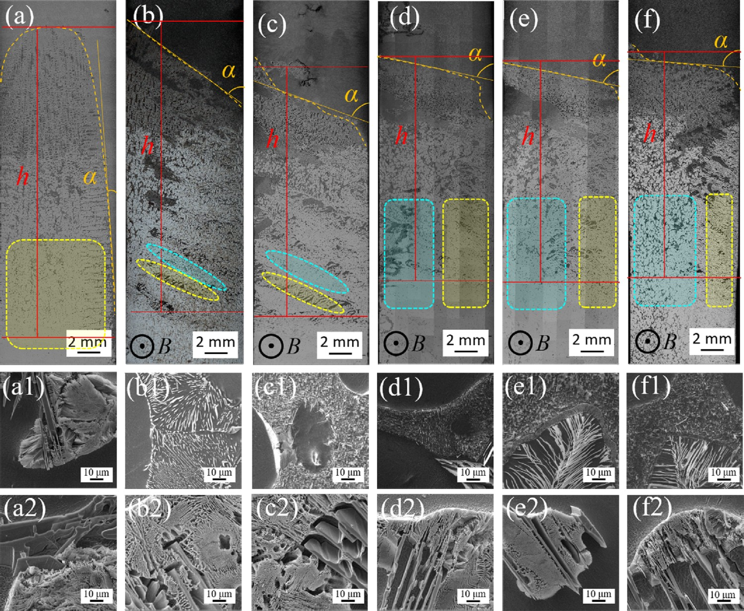
Values of α and h under various MFDs.
Chemical compositions and formation mechanism of LECs and FECs
The morphologies of the LECs and FECs in the ingot treated by 0.8 T were analysed. Figure 4(a,b) shows the three-dimensional morphologies of the lamellar carbides. It is seen that the LECs consist of several lamellae with 2–4 μm in thickness. The surface of lamella is rough and seems like steps which are considered to be the growth steep during the solidification [23]. Figure 4(c,d) exhibits the three-dimensional morphologies of FECs. From the deeply etched microstructure, the FECs are composed of smooth rods with diameters ranging from 1 to 2 μm. The morphology of the FECs can be further verified by the extracted FECs in Figure 4(d). The EDS maps of the LECs and FECs of the inserted figures in Figure 4(a,c) are shown in Figure 4(e,f). The results indicate that the constituents of both LECs and FECs are Fe, C, W, Mo, V and Cr elements. That is, the application of TSMF did not change the constituents of LECs and FECs. Typical morphologies of the eutectic carbides formed in the ingot treated by a 0.8 T TSMF. (a) and (c) are the deeply etched morphologies of LECs and FECs, respectively. (b) and (d) are the morphologies of the extracted LECs and FECs, respectively. (e) and (f) are EDS maps of the corresponding inserted figures in (a) and (c), respectively.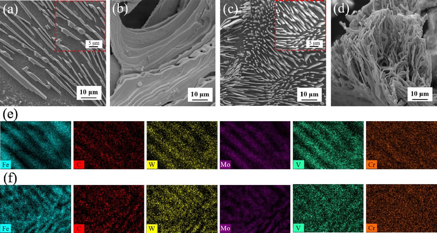
Chemical compositions of the LECs and FECs under vary MFDs (wt-%).
Figure 5 shows the XRD patterns of the extracted carbide powders. The types of eutectic carbides in the directionally solidified M2 high-speed steel are MC and M2C with or without a magnetic field. This proves that the TSMF did not change the type of eutectic carbide under various MFDs. XRD patterns of the eutectic carbide powders extracted from the directionally solidified M2 high-speed steels without and with a 0.4 T TSMF.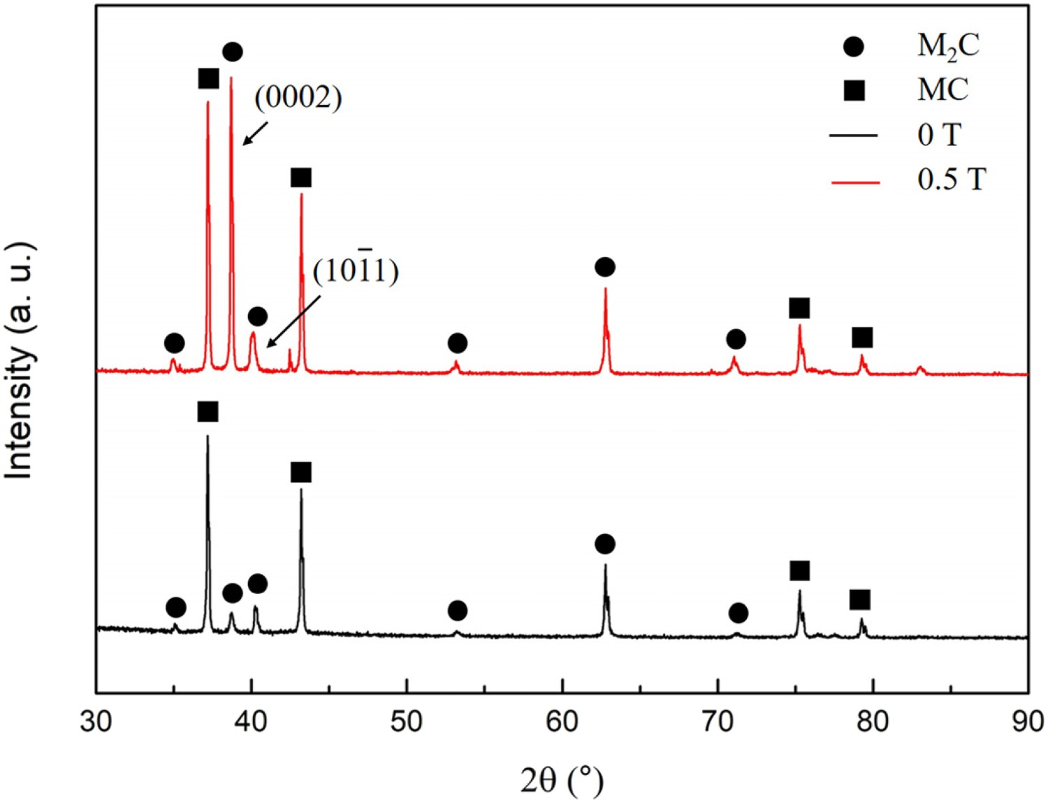
Discussion
Dynamic mechanism caused by TEMF
The phase transformation of high-speed steel has been researched by Barkalow et al. [24,25]. The solidification processes of high-speed steel are mainly divided into three parts: liquid → ferrite; ferrite + liquid → austenite; liquid→ eutectic structure. Austenite dendrites release the solute atoms into the liquid phase during the solidification process. The nature convection, which was caused by gravity, led to the migration of the released solute to around the dendrite tip and, thus, an inclined solid–liquid interface was formed (Figure 3(a)).
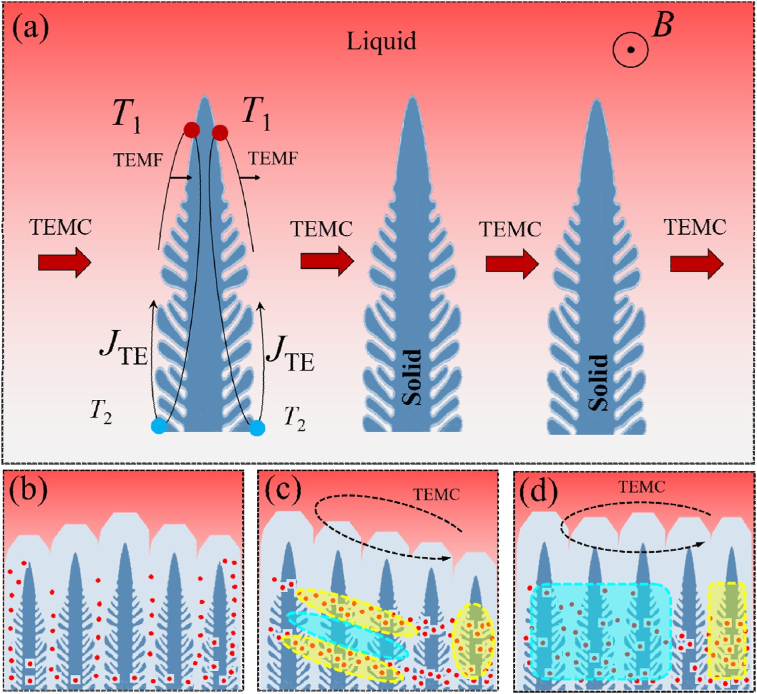
During the directional solidification, it is known that there is a temperature gradient between the dendrite tip and the dendrite root. The austenite dendrite and the surrounding liquid metal formed a closed current loop in the mushy zone during directional solidification. This current loop is the thermoelectric current (TEC) induced by the Seebeck effect [21] With the application of a TSMF, a TEMF as well as TEMC will be induced, as shown in Figure 6(a) and the expression of TEMF is written as follows: Schematic diagram of the physical mechanism of melt flow and solute movement.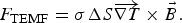
The magnitude of TEMC has been qualitatively analysed by Li et al. [19,21]. Combined with the experimental conditions in this paper, we can deduce the magnitude of the MFD and the corresponding maximum TEMC, which n be described below: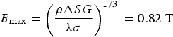
Based on the above calculations, as the MFD increases from 0 to 0.8 T or even 1 T, the intensity of the TEMF or TEMC gradually increases. Lots of studies show that the solutes migrate with the TEMC [15–18,21] and results from a difference in the composition of the solidified structure. When the MFD was relatively weak (0 –0.4 T), the TEMC will unidirectionally transport the rejected solutes to the right side of the sample. During the transporting process, the rejected solute atoms were trapped by the austenite dendrites. The enrichment of solute atoms between dendrites reduces the melting point of austenite at the root of the dendrite. This led to the remelting of the austenite dendrite and the formation of the segregation channel [22,28], as shown in Figure 6(c). With further increase of the MFD (0.6 –1 T), the intensity of TMEC increased and it is difficult for the dendrite to capture the solute atoms. Therefore, the segregation channels disappeared in the cases of large MFDs (0.6 –1 T). TEMC brought a large number of solute atoms to the right side of the sample to form LECs, which can be seen in Figure 3. However, the opposite side was accumulated by FECs. Previous results [29–31] indicated that the increase of V element promotes the formation of LECs. Therefore, the LEC forms in the segregation channel and at the right side of the sample, while FECs form at the left side of the sample.
Microhardness
As the above discussion, the solutes migrated with the TEMC between the α-Fe dendrites in the mushy zone and led to the morphology transition of the eutectic carbides from the LEC to the FEC. Simultaneously, the chemical composition of the eutectic carbide was also changed by the TEMF. It is deduced that the chemical composition of α-Fe matrix must be changed and led to the change of the number of precipitated carbides in the α-Fe matrix. This must lead to the change of the matrix microhardness on the transverse section of the sample. The matrix microhardness was measured by taking a point at an interval of 0.5 mm from the transverse section of the sample. The testing direction was perpendicular to the direction of the TSMF. The results are shown in Figure 7. When the MFD is 0 T, the microhardness of the matrix gradually increases. For the sample treated by a 0.4 T TSMF, the microhardness of the matrix deviate greatly. For the samples treated by 0.8–1 T TSMF, the deviation of microhardness reduced. This is consistent with the microstructures evolution in Figure 3. With the increase of MFD, the area covered by the FECs gradually increases. Thus, the microhardness of the matrix distributes uniformly. Microhardness on the cross sections of samples treated with various MFDs.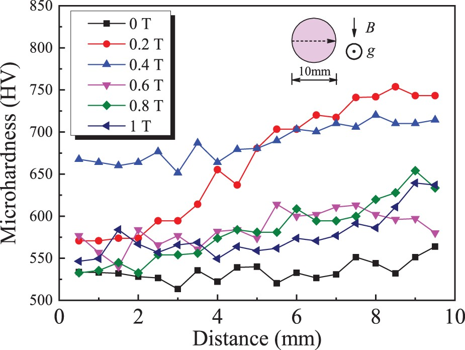
Conclusions
The morphology transition of eutectic carbide assisted by TEMF during the directional solidification of M2 high-speed steel under various TSMFs was studied. The main conclusions are listed below: After the application of a TSMF, the TEMF and TEMC were formed during the directional solidification of M2 high-speed steel. The morphology of the eutectic carbide in the solidified structure changed from a coarse lamella to a fine fibre. The morphology transition of eutectic carbide was determined by the amount of V elements. LECs formed at V-rich region. And FECs formed at V-poor region. FECs appeared gradually with increasing the MFD from. The change of the V concentration was caused by the TEMF. Many segregation channels were formed when the MFDs were 0.2 and 0.4 T. However, they disappeared when the MFDs were 0.6, 0.8, and 1 T. When the MFD was 1 T, the FECs nearly occupied the whole section of the ingot. This is a benefit for the fabrication of high quality of the ingot of M2 high steel.
Thus, by imposing a proper TSMF, it is a potential new method to control the morphology transition of eutectic carbide from lamellar to fibre and obtain an ingot of M2 high steel with FECs uniformly distributed in the austenite dendrites.
Footnotes
Acknowledgements
This work was supported by the National Key Research and Development Program of China [2016YFB0300401, 2018YFF0109404]; the National Natural Science Foundation of China [U1860202, U1732276, 51904184, 51704193, 52004156]; Users with Excellence Program of Hefei Science Center CAS (2019HSC-UE010); Changjiang Scholars Program of China.
Disclosure statement
No potential conflict of interest was reported by the author(s).