
Abstract
The kinetics of the reduction of magnetite concentrate particles by H2+CO mixtures have been investigated in drop-tube reactors (DTRs) to obtain rate expressions for the design of novel flash ironmaking reactors. The experimental temperature varied from 1423 K (1150°C) to 1873 K (1600°C). The H2/CO ratio was varied from 0.5 to 2, which is the typical composition range of the product gas from the partial oxidation of natural gas. The experimental data were analysed separately in two temperature ranges 1423 K (1150°C)–1623 K (1350°C) and 1623 K (1350°C)–1873 K (1600°C), as the magnetite concentrate particles tend to fuse and melt at temperatures above 1623 K (1350°C) changing the reduction mechanism. CFD (Computational Fluid Dynamics) simulations were used to more accurately account for temperature and concentration variations. Synergistic effects were observed in the reduction by H2+CO mixtures compared with the simple summation of contributions of the individual component gases.
Introduction
The blast furnace process accounts for more than 90 pct of the annual production of primary iron, according to the World Steel Association, with the balance by alternative processes such as direct reduction and smelting reduction. Owing to high energy consumption, environmental pollution and CO2 emissions, a great deal of efforts have been devoted to find an alternative low-cost process which is more environmentally friendly. Processes like direct reduction in the fluidised beds or in the shaft furnaces (MIDREX) have been successfully developed and built in iron and steel industry. These processes, however, cannot be operated at high temperatures due to the sticking and fusion of the particles. Therefore, they are not sufficiently intensive to replace the blast furnace. A novel ironmaking technology has been developed at the University of Utah [1–16]. In this process, iron is produced from fine iron oxide concentrate in a flash reduction process, utilising hydrogen, natural gas, or coal gas as the reducing agent as well as the fuel. A schematic of the overall process based on the flash technology is shown in Figure 1. The reduction rate described in this article is relevant to the flash shaft on the left-hand side of this figure. Flash ironmaking allows the direct use of iron oxide concentrate to bypass the pelletisation/sintering and cokemaking steps in the blast furnace reactor, which will significantly decrease the CO2 emissions as well as the energy consumption. A schematic diagram of a possible direct steelmaking process based on flash ironmaking technology (FIT).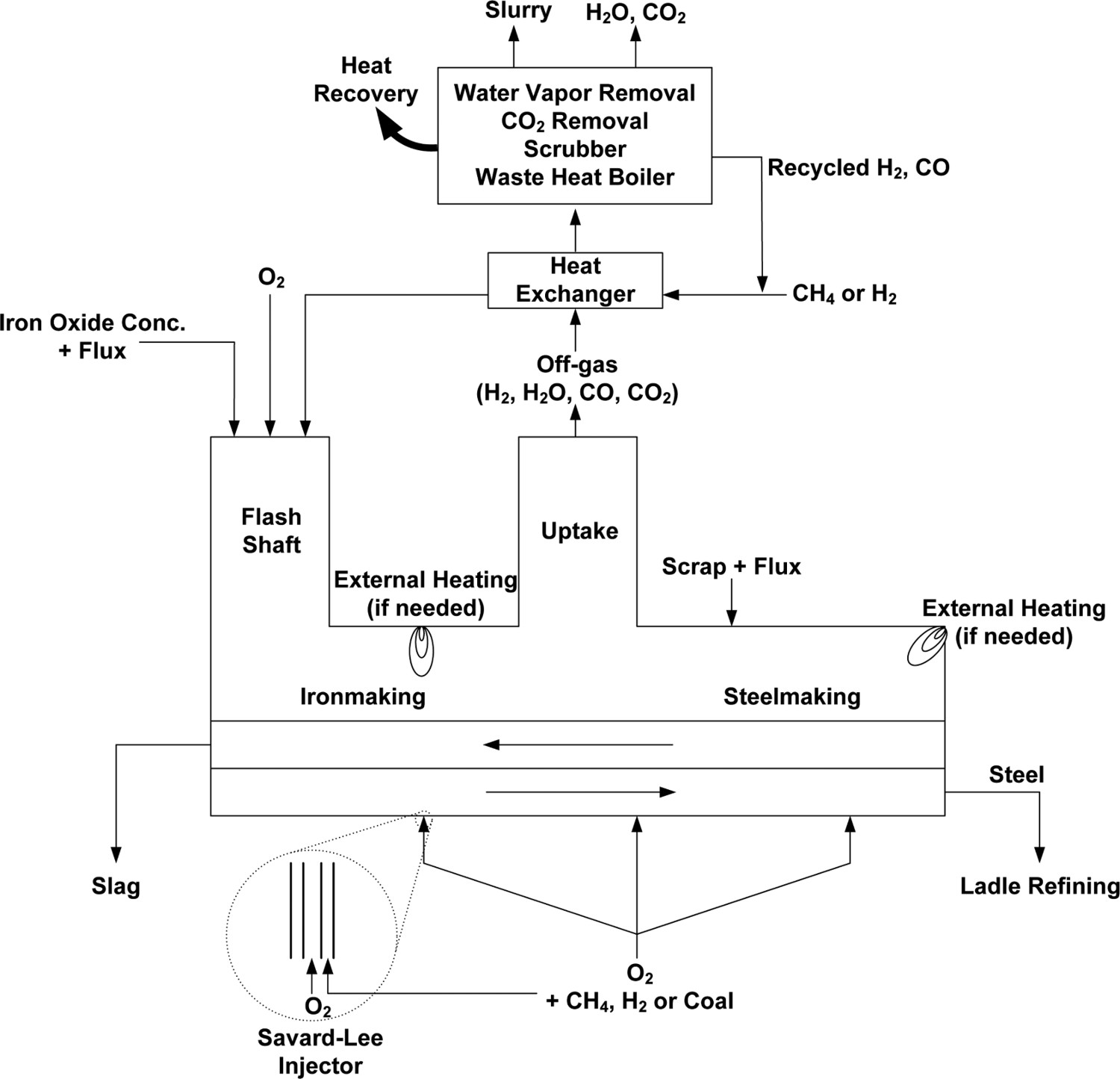
There have been other alternate processes developed to utilise fine iron-ore particles such as direct iron-ore smelting (DIOS) process [17] that uses coal to smelt iron-ore fines into molten iron, Hlsmelt process [18] in which iron-ore fines with minimum pretreatment together with fluxes and non-coking coal are injected into the slag layer on top of a hot metal bath, and HISarna ironmaking process [19] that combines a cyclone converter for ore melting plus pre-reduction and a smelting reduction vessel for the final reduction to liquid iron. In HIsmelt, post-combustion of the off-gas generated from the iron oxide reduction by oxygen-enriched air provides the energy needed for the process[18]. The HIsarna process is reported to be more energy-efficient and has a lower carbon footprint than the blast furnace process[19]. It is noted, however, that there could be 1–2 orders of magnitude difference between the average particle sizes of iron-ore fines and iron-ore concentrate particles.
The gaseous reduction of iron oxide was investigated previously by many other researchers but such work was more often than not focused on pellets or particles larger than concentrate particles at temperatures lower than the level expected in a flash reduction process.
Johnson and Davison [20] studied the reduction of taconite concentrate particles ranging in size from 5 to 45 μm in a heated cyclone. Natural gas was burned to preheat the cyclone to 1273 K (1000°C)–1473 K (1200°C) before switching to a plasma system to maintain an average operating temperature of 1773 K (1500°C) or higher. The iron-ore concentrate particles were reduced using CO as the reducing gas and a reduction degree of 80–95% was achieved.
Kazonich et al. [21] built a prototype reactor using rocket technology in which magnetite concentrate particles (−44 µm) were completely reduced in less than 50 ms. The temperature range in their reactor was 1200–2500°C, and the pressure was maintained between 12.8 and 16.8 atm. Propane (C3H8) was partially oxidised by pure oxygen to produce a reducing atmosphere that consisted mainly of H2 and CO.
Takeuchi et al. [22] investigated the in-flight reduction of spherical wustite particles ranging from 32 to 45 μm in diameter in a CH4 atmosphere. Their experimental temperature range was between 1100°C and 1300°C. At 1573 K (1300°C), complete reduction was achieved at a residence time of less than 1 s under a 11% CH4–N2 atmosphere. The experimental results showed that the reduction degrees achieved with CH4 were higher than that obtained with either H2 or CO. They proposed that CH4 first decomposed into carbon and hydrogen, which then reduced wustite to form the initial metallic iron shell around the particle. Then, the deposited carbon diffused through the metallic iron shell to further reduce the remaining wustite. They concluded that the chemical reaction of diffused carbon and wustite on the Fe–FeO was the determining step.
Geassy et al. [23] investigated the reduction of Fe2O3 briquettes with H2+CO mixture in the temperature range of 973 K (700°C)–1373 K (1100°C). They showed that adding H2 to CO enhanced the reduction rate. Reduction rate with pure H2 gas was faster than that with pure CO, and a mixture gave an intermediate reduction rate.
Moon et al. [24] studied the reduction kinetics of haematite compacts (1.78 cm in diameter and 0.78 cm in height) by H2+CO mixtures between 1073 K (800°C) and 1223 K (950°C) in a thermogravimetric analyser (TGA). They reported that the reaction rate increased with an increase of H2 content in the gas mixture, and the carbon deposition decreased with temperature (from 2.94 wt-% at 1073 K (800°C) to 0.48 wt-% at 1223 K (950°C). The reduction rate by H2 was 2–3 times faster than that by CO. They also obtained the effective diffusivity values for H2 and CO, and the value of that for H2 was 3–4 times higher than that of CO. They determined that chemical reaction at the oxide/iron interface dominated the reaction initially and then the reduction rate was controlled by the diffusion of reducing gas through the product layer until the end of reduction. The activation energy was determined to be in the range of 19.8–42.1 kJ mol−1 depending on the CO/H2 composition.
Bonalde et al. [25] investigated the reduction kinetics of haematite pellets, 1.07 and 1.24 cm in diameter, with a mixture of CO and H2 at 1123 K (850°C). The gas composition used in the experiments was 55.7% H2, 34% CO, 6.3% CO2 and 4% CH4 by volume. The effect of external mass transfer was eliminated by using a sufficiently high gas flow rate. The grain model was used to describe the kinetics of the reduction reaction. The reduction process was mixed controlled during the first stage of the reduction, while gas diffusion dominated the last stage of the reduction.
Piotrowski et al. [26] investigated the reduction of haematite powder (average size 91 μm) to wüstite using the TGA system with a gas mixture of 90%N2+4.3%H2+5.7%CO in the temperature range of 973 K (700°C)–1183 K (910°C). The activation energy obtained was 58.1 kJ mol−1. A mathematical model that combines the Avrami–Erofeyev model with n = 1.6 and the 1-D diffusion model was built for the kinetics analysis as it was not possible to describe the conversion accurately using only a single model. The Avrami–Erofeyev model was able to reproduce experimental results at less than 50% conversion. Then, the reaction shifted to a diffusion-controlled mode. The 1-D diffusion model was used to capture the mass transfer through the thick reaction product layer.
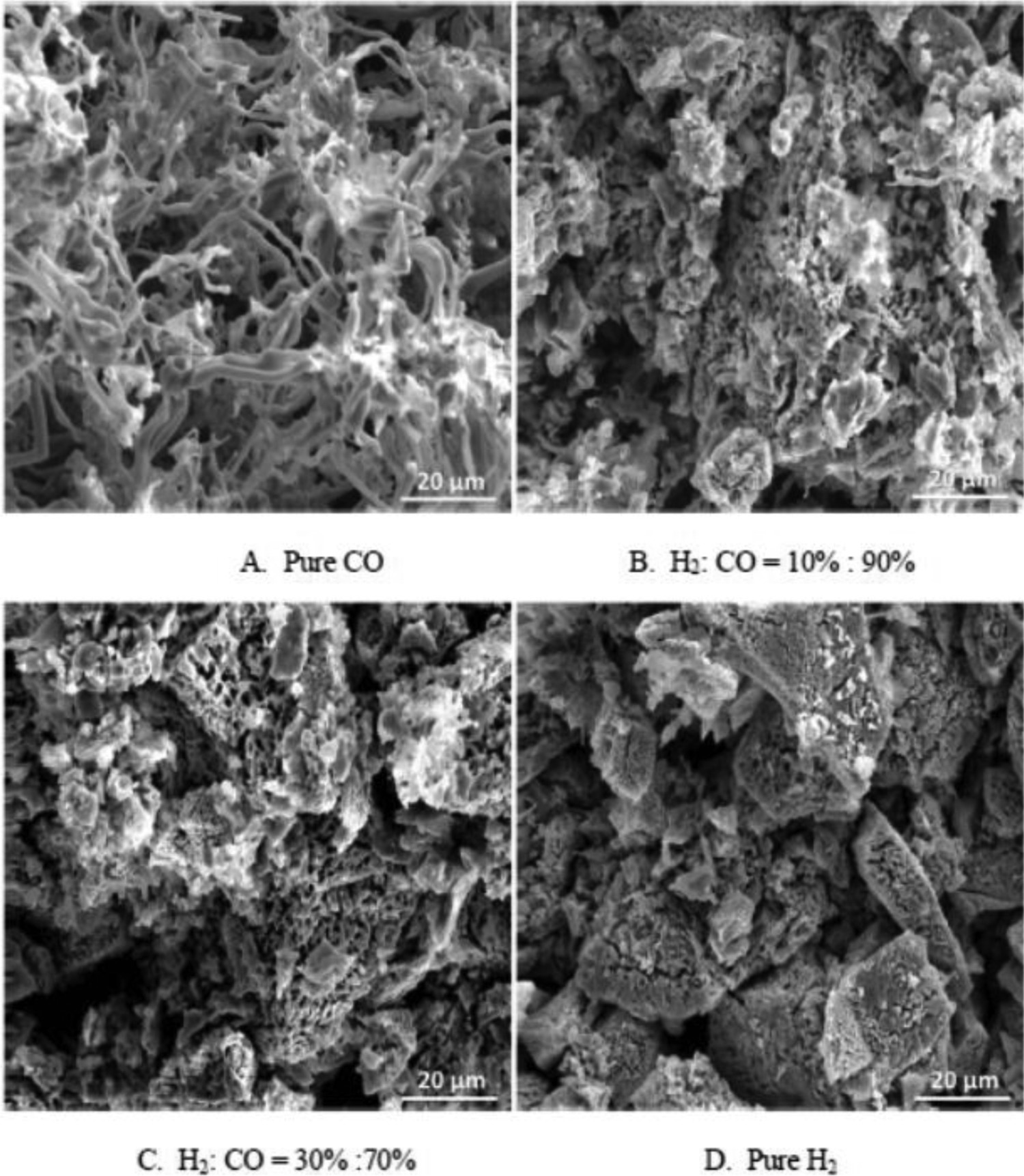
Wang and Sohn [27] investigated the effects of reducing gas on the swelling and iron whisker formation during the reduction of iron oxide compact. Cylindrical compacts 13 mm in diameter and 6 mm in height were prepared by hydraulic pressure and sintered at 1273 K (1000°C). The compacts were then reduced isothermally at 1173 K (900°C) in a TGA system under different reducing atmospheres. The results indicated that catastrophic swelling can happen when CO was used as the reducing agent. But when H2 was present in the reducing gas mixture, the catastrophic swelling disappeared. SEM micrographs showed that catastrophic swelling was caused by a large amount of long iron whiskers formed during the reduction. The presence of N2 and CO2 in CO changed the amount of long iron whiskers, which determined the extent of swelling. Although the formation of whiskers was greatly suppressed when H2 was present, the morphology of the reduced iron under H2+CO indicated higher porosity than that reduced under pure H2.
Zuo et al. [28] studied the reduction of haematite pellets by H2 + CO mixtures at different reducing temperatures (1073 K (800°C), 1173 K (900°C), 1273 K (1000°C)). They showed that the effective diffusion coefficient and the rate constant of chemical reaction were simultaneously enhanced with increasing temperature or increasing H2 content in the mixture. The reduction of iron oxide pellets by H2 + CO mixtures was mixed controlled; the reaction rate was dominated by chemical reaction at the very beginning, simultaneously by reaction and diffusion during reduction process, and by internal gas diffusion at the end.
Nyankson and Kolbeinsen [29] investigated the reduction of iron-ore pellet by CO + H2 gas mixtures. It was shown that the reaction was limited by chemical reaction at the beginning stage. Later, gas diffusion played an important role.
Qu et al. [30] investigated the reduction kinetics of haematite ore fines by CO + CO2 mixtures in a drop-tube reactor (DTR). A series of experiments with different residence time (210–2020 ms) were conducted at 1550–1750 K. It was found that micro pores were formed during the reduction process due to the loss of oxygen. The shrinking unreacted-core model was used to describe the reaction kinetics and the activation energy obtained was 270 kJ mol−1.
Sohn and co-workers [9–16] have investigated the gaseous reduction of iron oxide concentrate particles under various experimental conditions using a DTR aimed at generating a database to be used for the design of a flash ironmaking reactor. In the most likely near-term industrial application of this technology, the partial combustion of natural gas with industrial oxygen is expected to be used to produce the hot reducing gas. The gas mixture thus obtained contains reducing gases H2 and CO.
In this work, the kinetics of the reduction of magnetite concentrate particles by H2+CO mixtures was investigated in DTR. The experimental temperature was varied from 1423 K (1150°C) to 1873 K (1600°C), which is the expected operational temperature range of a flash ironmaking reactor. The H2/CO ratio was varied from 0.5 to 2, which is the typical composition range of the product gas from the partial oxidation of natural gas. The purpose of this work was to generate the rate expression for the reduction of magnetite concentrate particles by H2+CO mixtures based on the rate expressions of reduction by individual component gases. CFD analysis was used to improve the accuracy by eliminating the effect of temperature variation of the particles encountered in the DTR.
Experimental work
Chemical composition of magnetite concentrate used in this work.
A sketch representing the two similar reactors is shown in Figure 2. The reactor tubes were made of 99.8% purity alumina, which had inner diameters of 5.6 and 8 cm, respectively, in the lower and higher temperature DTR. The carrier gas used in all experiments was either N2 or CO, which was maintained at a constant flow rate of 0.3 L min−1. (Flow rates in this work were all calculated at 298 K (25°C) and 0.85 atm, the atmospheric pressure at Salt Lake City.) A water-cooled tube was used so that no chemical reaction of the particle took place before entering the reactor. A cylindrical porous alumina honeycomb was inserted at the top part of the reactor to enhance the mixing and preheating of the reducing gas as well as to distribute the input gas uniformly over the reactor cross-section. Further details about the DTRs, including the particle feeding system, can be found in our previous publications [9–12,14]. A sketch of DTR.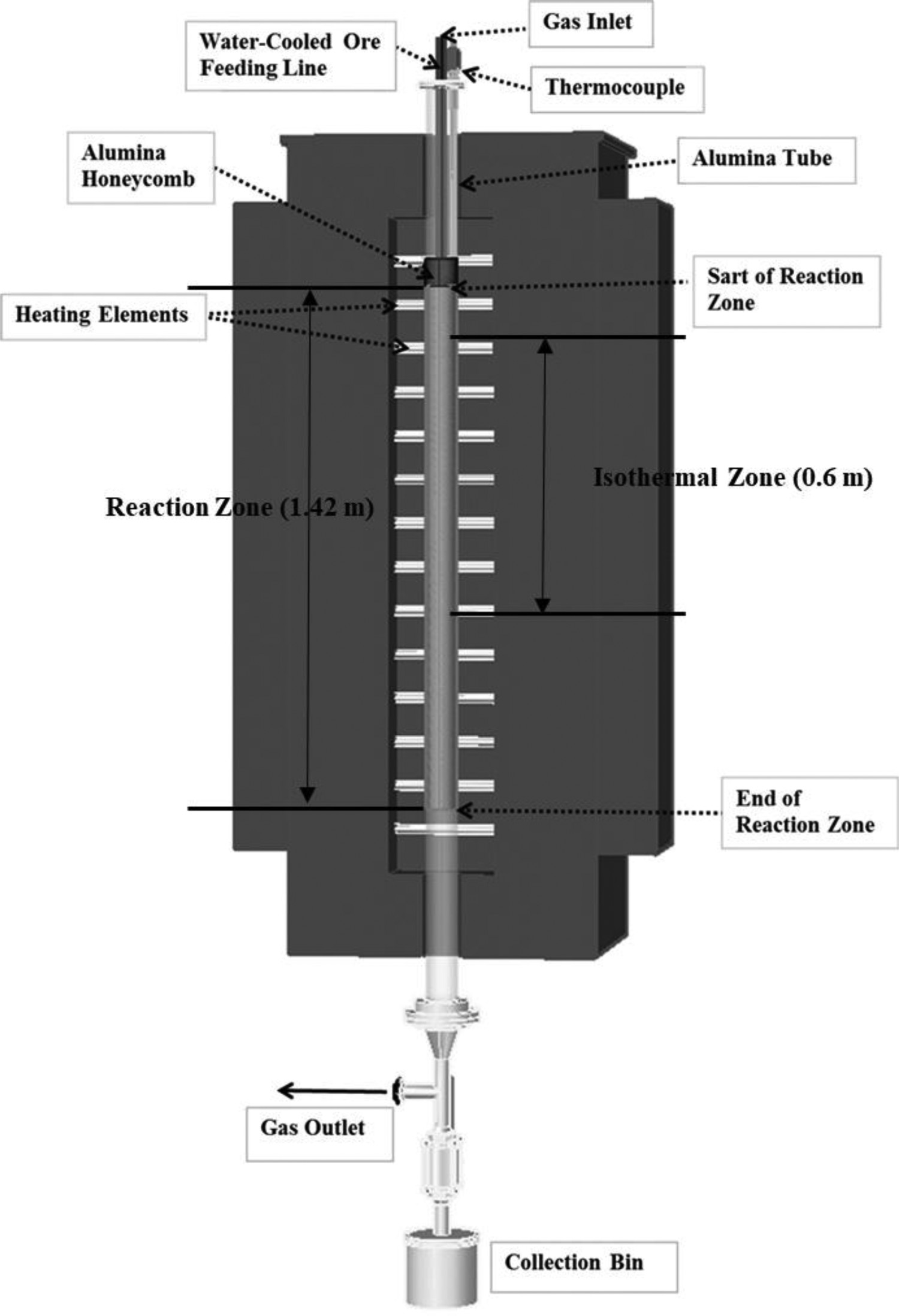
Dried and screened magnetite concentrate particles of size fraction 20–25, 32–38, or 45–53 µm were used in the experiments. In the flash ironmaking process, the particle residence time is expected to be 2–10 s. The gas flow rates were adjusted in this work to provide these residence times while allowing desired reduction degrees depending on other experimental conditions such as temperature and gas composition. During the experiment, the particle feeding rate was controlled in the range of 30–200 mg min−1. The mass ratio of particles to gas was kept at ≤0.05. The complete experimental data of the reduction of magnetite concentrate particles by H2+CO mixtures under various conditions are listed in the Appendix. For all the experiments, the feed rates of the individual reducing gases (H2 and CO) were in more than 500% excess of the minimum required amount for complete reduction by each gas to ensure that the gaseous reactant concentration remained essentially constant over the entire reactor length. The reacted powder was collected in a powder collector at the bottom of the reactor.
Mathematical model
The Euler–Lagrange approach was used to model the two-phase flow, in which the gas phase was treated as continuum in the Eulerian frame of reference while the solid phase was tracked in the Lagrangian frame of reference. For the gas phase, the realisable k–ϵ model [31] was chosen and the particles followed the gas near the centreline. Radiation from the wall was taken into account using the discrete ordinate (DO) model [32]. The general steady-state transport equation is given by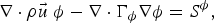


Solid phase governing equations.
In the reduction process, the reducing gases adsorb onto the active sites and react with oxygen and produce Fe nuclei that grow with time. For small particles, the period of the formation and growth of nuclei occupies essentially the entire conversion range. It is extremely difficult, if not impossible, to measure the intrinsic kinetics involving the formation of wustite for small particles going through a rapid reduction. In addition, different parts of a small irregular iron oxide particle react at different rates and thus different oxide phases coexist in the particle at any time, as shown in Figure 3. Therefore, a global nucleation and growth rate expression for the overall reduction process was adopted in this work. Coexistence of various iron oxide phases along with iron as indicated by XRD of quenched samples of different reduction degrees.


A simple additive relationship was first assumed between the overall oxygen removal rate and the rates by its component gases as Comparisons between the calculated reduction degrees by Morphologies of partially reduced iron or concentrate particles showing the effect of CO gas.

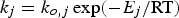
Comparison of the reaction rate at different temperatures with X = 0.5 for magnetite reduction by CO and H2 individually.


In Equation (4), 
Results and discussion
Results
Optimum values for a and b.
Typical calculated reduction degrees along the reactor length obtained using the optimum values listed in Table 5, together with the corresponding experimental reduction degrees and temperature profiles, are shown in Figures 6 and 7. It is seen that the simulated reduction degree values match the experimental values very well. Calculated profiles of particle temperature and unreacted fraction along the reactor length in the lower temperature range. − · −: pCO = 0.4 atm, pH2
= 0.2 atm, gas flow rate: CO: 1.6 L min−1, H2: 0.8 L min−1, N2: 1.0 L min−1; − − −: pCO = 0.15 atm, pH2
= 0.3 atm, gas flow rate: CO: 0.6 L min−1, H2:1.2 L min−1, N2: 1.6 L min−1; − ·· −: pCO = 0.2 atm, pH2
= 0.1 atm, gas flow rate: CO: 0.6 L min−1, H2: 0.3 L min−1, N2: 1.6 L min−1. Reactor inner diameter: 5.6 cm, dp = 22.5 µm for all three cases. The temperature values in the legend represent the experimental temperatures. Each of the experimental conditions was repeated three times and the reduction degree results were found to be within ±5%. Calculated profiles of particle temperature and unreacted fraction along the reactor length in the higher temperature range. − · −: pCO = 0.2 atm, pH2
= 0.1 atm, gas flow rate: CO: 1.6 L min−1, H2: 3.2 L min−1, N2: 8.8 L min−1, dp = 35 µm; − − −: pCO = 0.1 atm, pH2
= 0.1 atm, gas flow rate: CO: 1.5 L min−1, H2: 1.5 L min−1, N2: 9.8 L min−1, dp = 49 µm; − ·· −: pCO = 0.1 atm, pH2
= 0.1 atm, gas flow rate: CO: 1.0 L min−1, H2: 1.0 L min−1, N2: 6.3 L min−1. Reactor inner diameter: 8 cm, dp = 22.5 µm. The temperature values in the legend represent the experimental temperatures. Each of the experimental conditions was repeated three times and the reduction degree results were found to be within ±5%.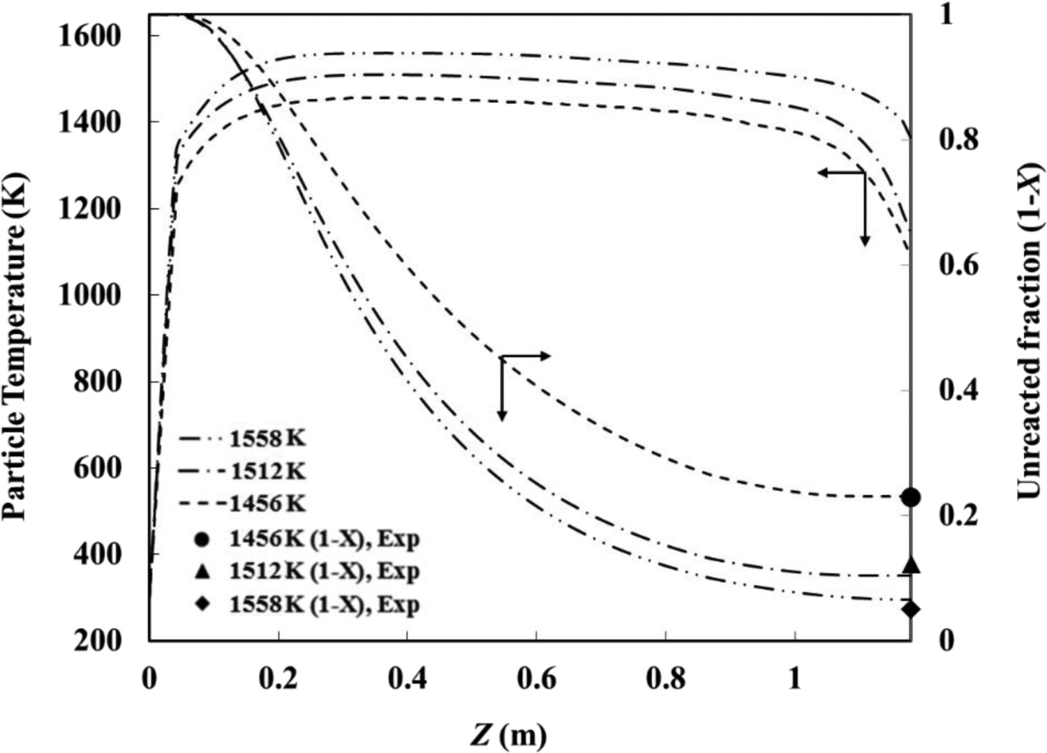
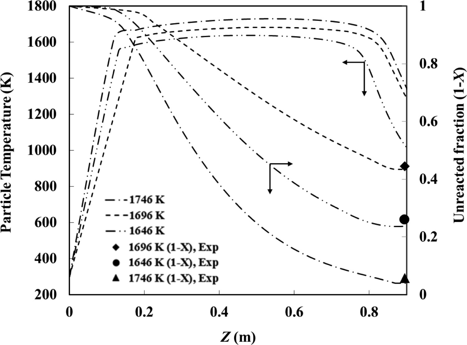
The results computed based on the CFD method demonstrates that a low-temperature region existed adjacent to the water-cooled injection tube in the top part, and the particle temperature decreased gradually in the bottom part of the reactor. It is seen from Figures 6 and 7 that it takes about 0.1 m from the tip of the injection tube for the particle temperature to reach the ‘uniform’ isothermal temperatures. The existence of this low-temperature zone in the upper part of the DTR affects the calculation of real particle residence time. From Figure 7, it is also seen that larger particles are heated more slowly.
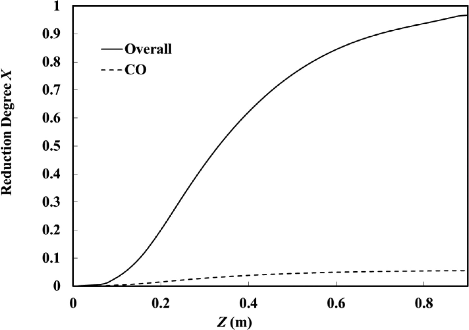
The CO contributions in the reduction of magnetite concentrate particles are calculated and shown in Figures 8 and 9. It is seen that the part of contribution that CO plays in the overall reduction is less than 2% in the lower temperature range, while in the higher temperature range, its contribution can raise to around 6%. But overall, the CO contribution to the overall reduction is small. CO component gas contribution to the overall reduction at the experimental temperature T = 1512 K: pCO = 0.4 atm, pH2
= 0.2 atm, gas flow rate: CO: 1.6 L min−1, H2: 0.8 L min−1, N2: 1.0 L min−1. CO component gas contribution to the overall reduction at the experimental temperature T = 1746 K: pCO = 0.2 atm, pH2
= 0.1 atm, gas flow rate: CO: 1.6 L min−1, H2: 3.2 L min−1, N2: 8.8 L min−1, dp = 35 µm.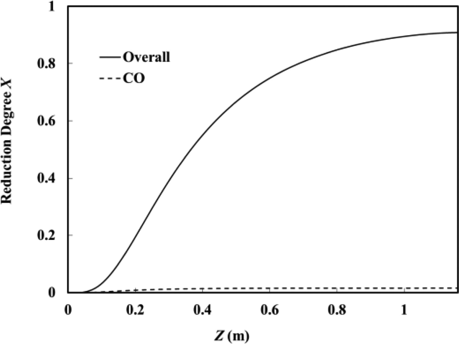
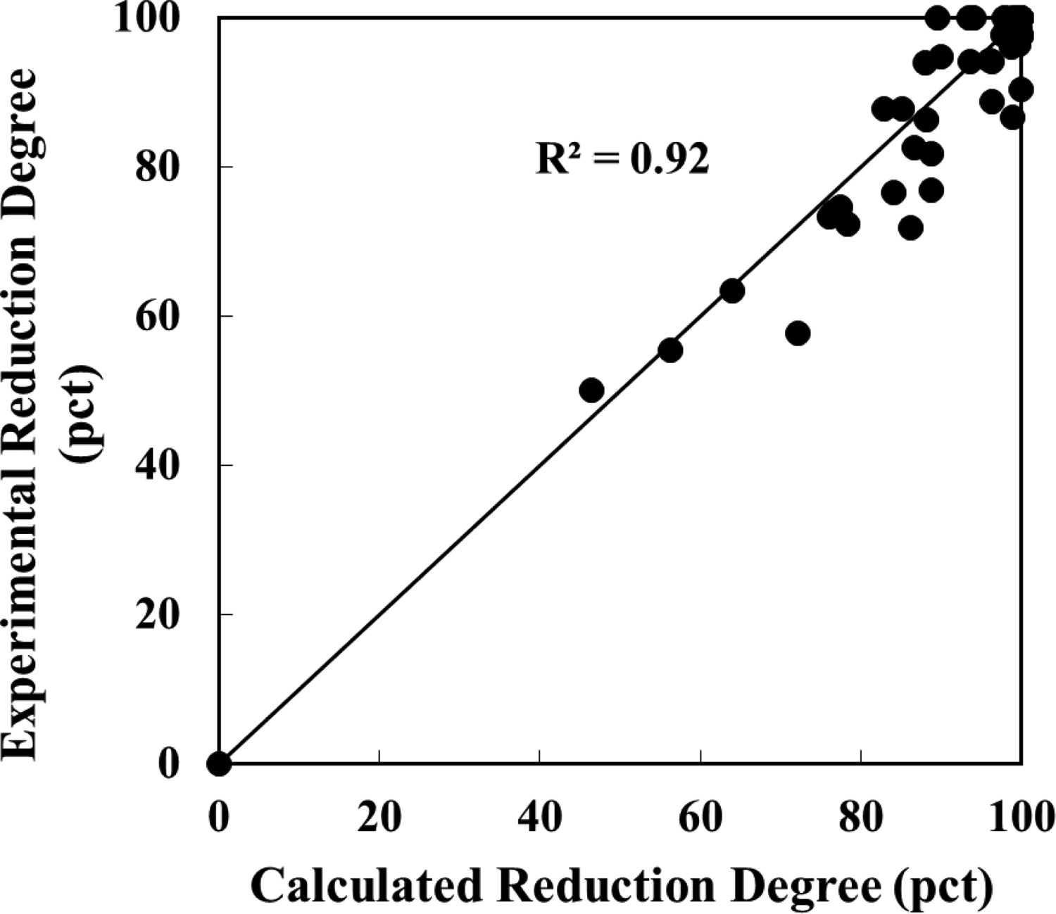
The comparisons between the calculated reduction degrees using the optimum values of a and b and the experimental values are shown in Figures 10 and 11 for the reduction of magnetite concentrate particles by H2+CO mixtures in the lower temperature range [1423 K (1150°C)–1623 K (1350°C)] and higher temperature range [1623 K (1350°C)–1873 K (1600°C)], respectively. It is noted that the optimum values of a and b obtained predict the reduction degrees very well. Thus, the rate expression proposed as Equation (4) by incorporating an enhancement factor can be used with confidence to describe the reduction of magnetite concentrate particles by H2+CO mixtures. Comparisons between the calculated reduction degrees vs. experimental results by H2 + CO mixtures in the lower temperature range. Comparisons between the calculated reduction degrees vs. experimental results by H2 + CO mixtures in the higher temperature range.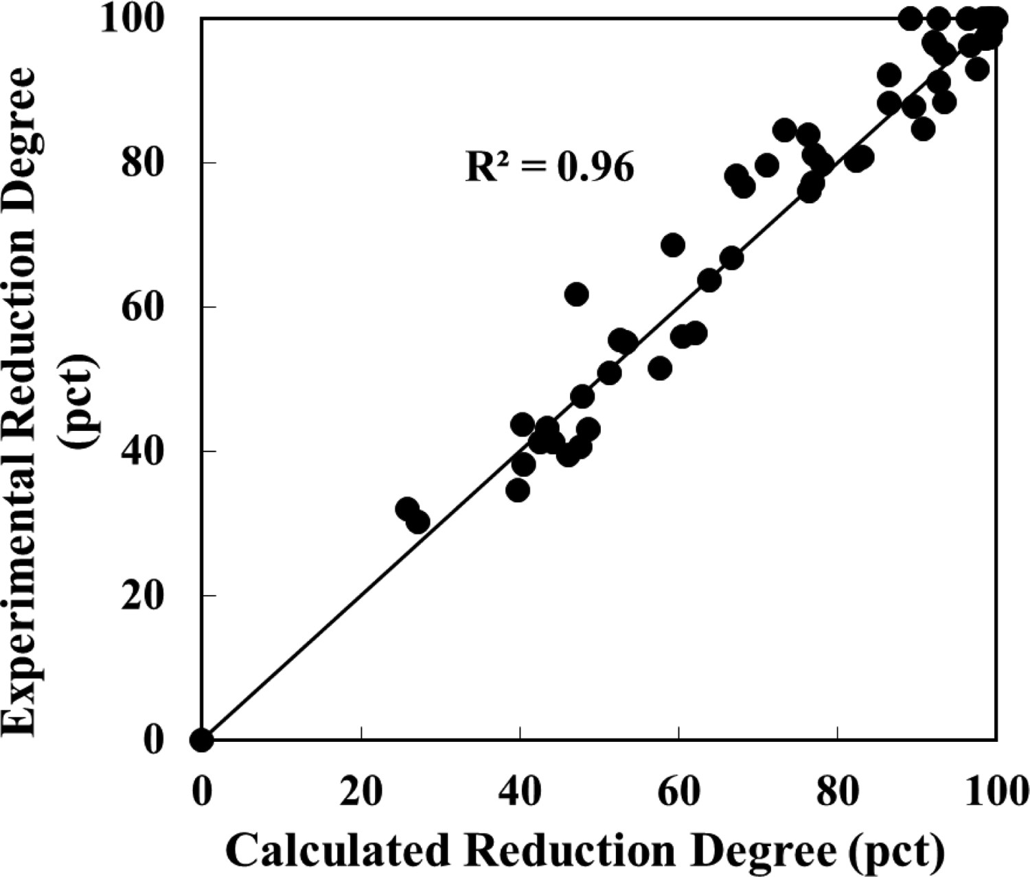
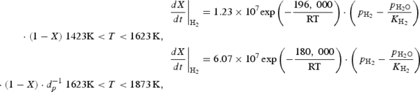
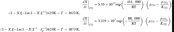
Complete rate expressions
The complete rate equations for the reduction of magnetite concentrate particles by H2+CO mixtures in the temperature ranges 1423 K (1150°C)–1623 K (1350°C) and 1623 K (1350°C)–1873 K (1600°C) are given, respectively, as:

Although the use of CFD technique should in principle allow one to determine the rate expression even from experiments done under spatially varying temperature, velocity and gas concentrations, the accuracies of the developed rate equations and parameters are greatly enhanced by performing the experiments designed to keep these conditions as uniform as possible, in combination with CFD simulation to account for small variations that are difficult to completely eliminate. This is the approach we used in this work.
Conclusions
A one-way coupling CFD method was used in this work to account for the effects of the small variations of particle temperature and velocity inside the reactor. Synergistic effects were observed in reduction by H2+CO mixtures compared with the simple sum of contributions by the individual component gases. In order to account for this enhanced effect, an enhancement factor which is a function of temperature and partial pressures of H2 and CO was introduced in the rate expression. The enhancement factors for the reductions in the lower and higher temperature ranges were determined to be 

Footnotes
Acknowledgements
The support and resources from the Center for High Performance Computing at the University of Utah are gratefully acknowledged.
Disclosure statement
No potential conflict of interest was reported by the author(s). This report was prepared as an account of work sponsored by an agency of the United States Government. Neither the United States Government nor any agency thereof, nor any of their employees, makes any warranty, express or implied, or assumes any legal liability or responsibility for the accuracy, completeness, or usefulness of any information, apparatus, product, or process disclosed, or represents that its use would not infringe privately owned rights. Reference herein to any specific commercial product, process, or service by trade name, trademark, manufacturer, or otherwise does not necessarily constitute or imply its endorsement, recommendation, or favouring by the United States Government or any agency thereof. The views and opinions of authors expressed herein do not necessarily state or reflect those of the United States Government or any agency thereof.