
Abstract
It is very important to have a slag detection system (SDS) in steelmaking to detect slag and prevent its flow for improving the quality of steel produced. Slag raking is used for removing slag from liquid iron. Detection and control of slag may be carried out with the help of refractory dart or infrared imaging in the steel making zone such as in a Basic Oxygen Furnace (BOF). Each method has its advantages and limitations. Detection and control of slag flow from ladle to tundish in a casting operation is an important step towards cleanliness of the steel production. Various techniques such as ultrasonic level sensor, conductivity measurement using magnetic field, use of microphone to monitor the sound of steel flow through shroud, monitoring the radiation intensity of the stream of steel flow through a lateral side duct of the ladle shroud and monitoring of the shroud vibration have been explored to minimize the slag flow from ladle to tundish. It is obvious from literatures that non-contact based SDS is much more preferred using advanced instrumentation techniques. The problem with the vibration-based system is reduced metal level in the tundish due to setting up of slide gate of the ladle at low flow level as well as non-detection of the slag flow where vortex did not form prior to slag flow. Research showed improved performance with the vision-based caster SDS. Monitoring the sudden brightening of the slag surface around the pouring tube with the help of a CCD camera and image processing technique is also an effective way to detect slag transfer from ladle to tundish. The major limitation of this method is that a significant amount of slag already enters the tundish due to increased flow rate at the end of the tapping before splashing takes place. This work attempts to overcome this problem. There is an increased trend in the amplitude of the undulation of the slag surface of the tundish before the sudden brightening of the slag surface. If such undulations are identified by image analysis technique, signal can be generated to move the ladle slide gate to limit a significant amount of slag flow into the tundish. This would help to improve the quality of the steel that is produced.
Introduction
Continuous casting of steel is a process in which liquid steel is continuously solidified into a strand of metal. There are lots of problems in continuous casting shop like slag entrapment, mould breakout of liquid steel, etc., which affects the quality of the steel and productivity of the steel. The process of slag detection, removal and control take place at various stages of steel production. After the pre-treatment for desulfurization, desiliconization and dephosphorization of liquid pig iron from the blast furnace, slag is generated which floats on the surface of the liquid iron. This slag must be removed away otherwise it may cause significant deterioration in the quality of the next process of steel making. Raking system [1,2] is generally used for removing slag from liquid pig iron before pouring into the Basic Oxygen Furnace (BOF). A further slag control process takes place while pouring liquid steel from BOF to steel ladle for transportation to casting site. Refractory darts [3] are commonly used for slag arresting during tapping from BOF to ladle. Nowadays, an infrared imaging-based slag detection system (SDS) [4–8] is used for improving the performance of BOF slag detection. The final stage of slag detection and control takes place in the continuous casting site during tapping from ladle to tundish. Unlike tapping of open stream in BOF, slag and liquid steel flows through a cylindrical tube made of refractory materials called shroud in casting operation. The shroud is used to prevent the teeming stream from atmospheric contamination through air pick up and reoxidation of liquid steel that creates micro-inclusion in the finished product [9]. The heat loss of the molten steel is also an important reason for using refractory shroud. Rice husk ash is generally used as insulating materials to prevent heat loss of the molten steel in the tundish. However, the addition of rice husk ash increases silica activity in the tundish slag and as a result an increase in reoxidation of the molten steel in the tundish. The addition of calcium aluminate-based flux in tundish reduces the reoxidation process in molten steel [10]. The refractory shroud, carryover slag from ladle and the flux mentioned above prevents direct visibility of the slag flow from ladle to tundish. This limits the use of infrared camera for the detection of tundish slag. Kemeny and Walker [11] described various techniques for slag detection and control at casting site. The electromagnetic coil for conductivity measurement and ultrasonic level metres for slag detection are quickly worn out due to high temperature at the measurement site and are also very much maintenance intensive [12]. Monitoring the radiation intensity of the stream of steel flow through a lateral side duct of the ladle shroud requires the modification of each of the refractory shroud as well as slag flow will remain undetected when it flows through the centre of the stream [11]. At the end of the tapping from ladle to tundish, the flow increases considerably because of the appearance of the vortex in the ladle. The amplitude of the sound also increases which can be detected by a microphone. The sound amplitude decreases abruptly at the onset of slag flow from the ladle to tundish. The shroud vibration also shows a similar signature in vibration pattern as liquid steel and slag flow through the shroud. A skilled operator can sense the vibration pattern of the shroud by placing arm on the ladle shroud manipulator arm. This, however, depends on the skill and attentiveness of the operator and thus may produce inconsistent results. Piezoelectric-based accelerometer can be mounted on the shroud manipulator arm to detect the vibration amplitude [11–15] of the shroud. The problem with the vibration-based system is reduced metal level in the tundish due to setting up of slide gate of the ladle at low flow level as well as non-detection of the slag flow where vortex did not form prior to slag flow. Chakraborty and Sinha [16] showed the vision-based caster SDS. They noted a sudden (or sharp) increase in the light intensity as significant amount of slag flow takes place during the formation of vortex in the ladle and the large chunk of slag collides with the slag surface of the tundish. As light flashing takes place only after the slag enters the tundish, the method could not control the entry of a significant amount of slag flow in the tundish. Furthermore, the system is not capable of detecting slag where vortex did not form prior to slag flow. It has been observed that carryover slag from ladle and slag formed due to rice husk and calcium aluminate-based flux in the tundish form a layer on the molten metal of the tundish. Any slag carryover from the ladle causes an undulation in the slag layer of the tundish. The frequency and vibration amplitude of slag surface undulation increases with an increase in the slag flow rate during onset and the end of formation of vortex in the ladle since more and more big chunk of slag enters the tundish.
This work attempts to overcome the problem mentioned in the vision-based system by identifying the amplitude of slag surface undulation with the help of image analysis technique. This would help to improve the quality of the steel produced by limiting the slag transfer from ladle to tundish. The set-up can be thought of as an improvement in vision-based system described by Chakraborty and Sinha [16].
Methodology
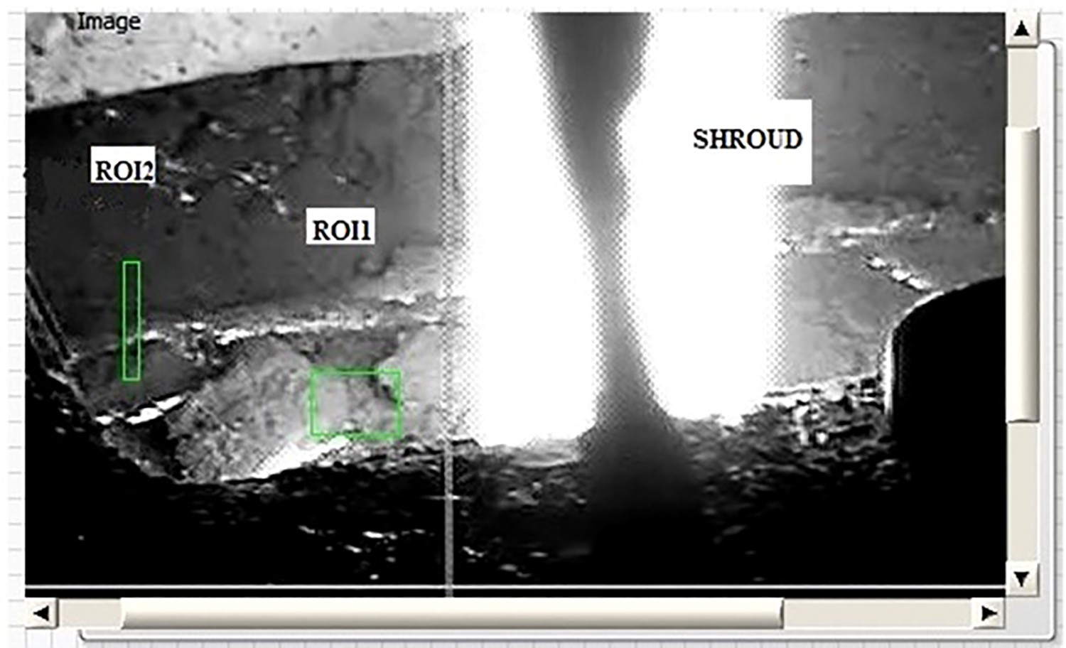
The schematic diagram of the measurement set-up at the casting site is shown in Figure 1. The ladle shown is mounted in a turret. The ladle is a huge metal container made of steel and of typical capacity of around 100–200 t and up and internally lined by refractory lining for transporting molten metal at around 1400–1700°C. Chakraborty and Sinha [17] briefly described the construction and operation of a steel ladle. Figure 1 also shows a refractory shroud through which liquid metal and slag flows from ladle to tundish and the connected mould for producing billets. A CCD/CMOS-based [18] video camera is shown to focus the area of the intersection of ladle shroud with slag layer of the tundish. The camera is connected to the computer for image processing applications. For efficient high-speed image data transfer in industrial application, GigE cameras [19] can be used which operates at data transfer speeds up to 10 GB s−1 and Ethernet links up to 100 m without any signal loss. Another advantage of GigE cameras is that they do not require any frame grabber card and data are brought to the PC with the help of a standard cost-effective network interface chip. A comparative study of different image data transfer protocols is shown by Chamberlain [20]. Progressive scan [21] digital monochrome cameras [19] with higher megapixel values in the range 8–16 MP and a higher frame rate such as 30–160 fps can be advantageous for our application since higher spatial resolution and detection of fast change in the scene are required. Figure 2 shows the image of slag layer in a tundish. The white cylindrical portion of Figure 2 is the image of the shroud. Schematic arrangement of the vision-based detection of slag layer undulation. Image of shroud and the slag layer of the tundish. The figure also shows ROI1 and ROI2.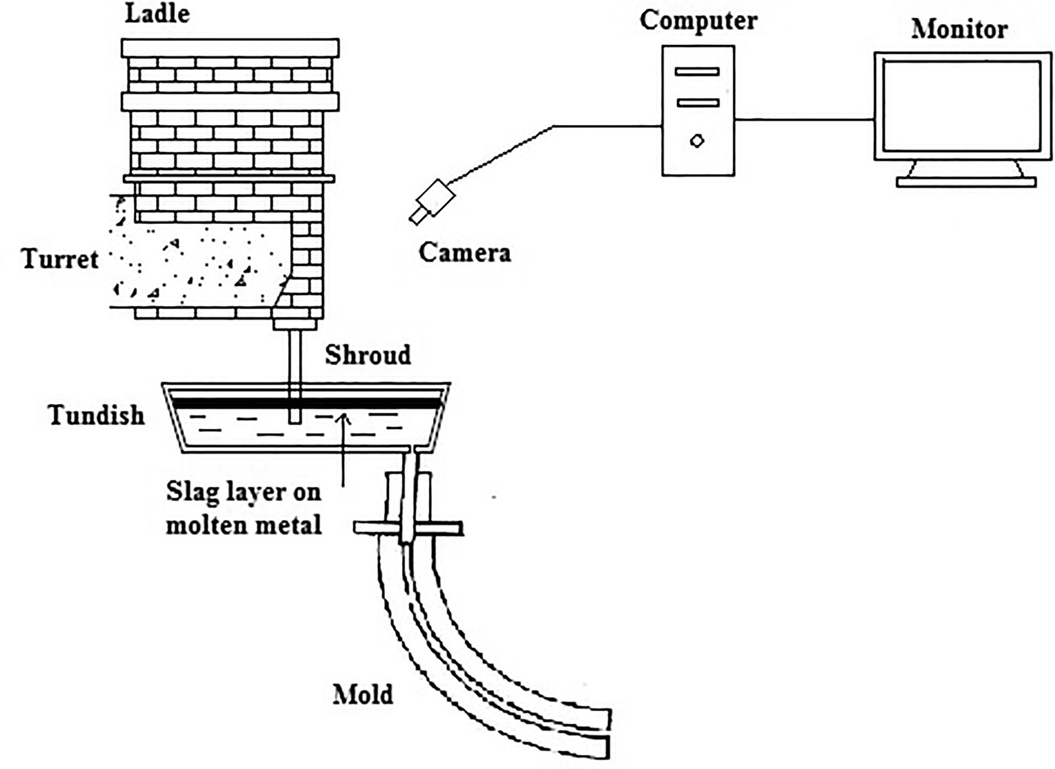
The processing is based on computing the statistical features of an image, which are arithmetic mean and standard deviation [22]. The arithmetic mean is the average grayscale value of the image. The standard deviation is calculated to find out the deviation of measured pixel values of an image from its arithmetic mean value. If the intensity of an image is uniform throughout, the standard deviation should be small. A small standard deviation indicates that pixel intensities do not vary far from the mean. A large value of standard deviation indicates pixel intensities are scattered throughout the image and at the same time far from the arithmetic mean value. The expressions for arithmetic mean and standard deviation of an image can be expressed as

In our application, the variation of standard deviation with time indicates the variation of scattered pixel intensities with time from its arithmetic mean value. Figure 3 shows the flowchart for developing software in LabView platform with IMAQ vision support. ROI1 is used to calculate the mean gray level intensity (arithmetic mean) of the image pixels bounded by the Region of Interest 1 (ROI1). ROI2 is used to calculate the standard Deviation of the image pixels bounded by the Region of Interest2 (ROI2). ROI1 is drawn near to the intersection of the shroud with slag level of the tundish to catch the maximum effect of the light flashing, whereas ROI2 is drawn at a distance where the effect of light flashing is minimum and the change in standard deviation is due to variation in surface undulation. It is also possible to calculate the mean gray level intensity of ROI2 to demonstrate the effect of slag surface undulation, but the change in mean intensity variation is not pronounced as the change in standard deviation with slag surface undulation. Flowchart for software development.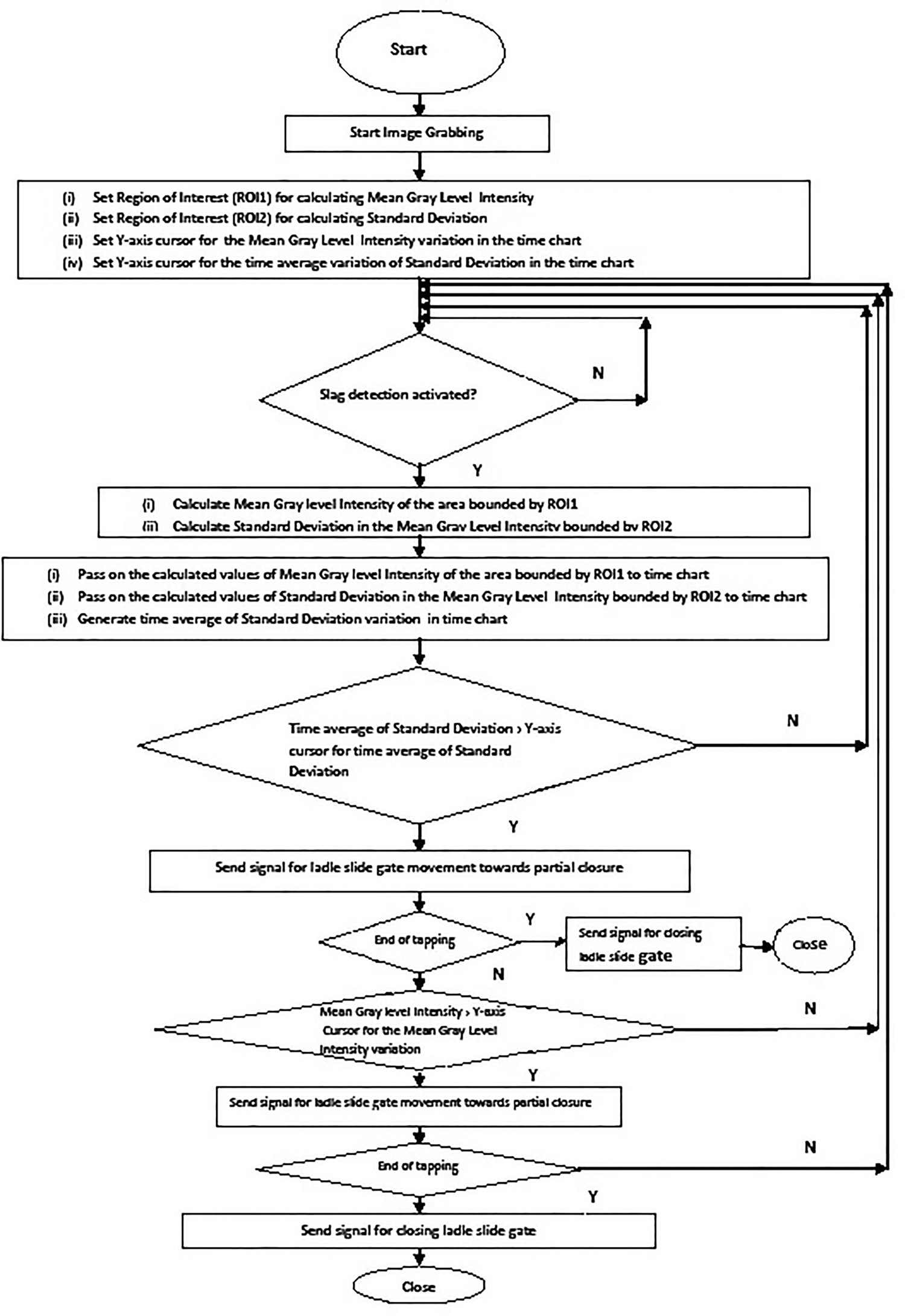
Results and discussions
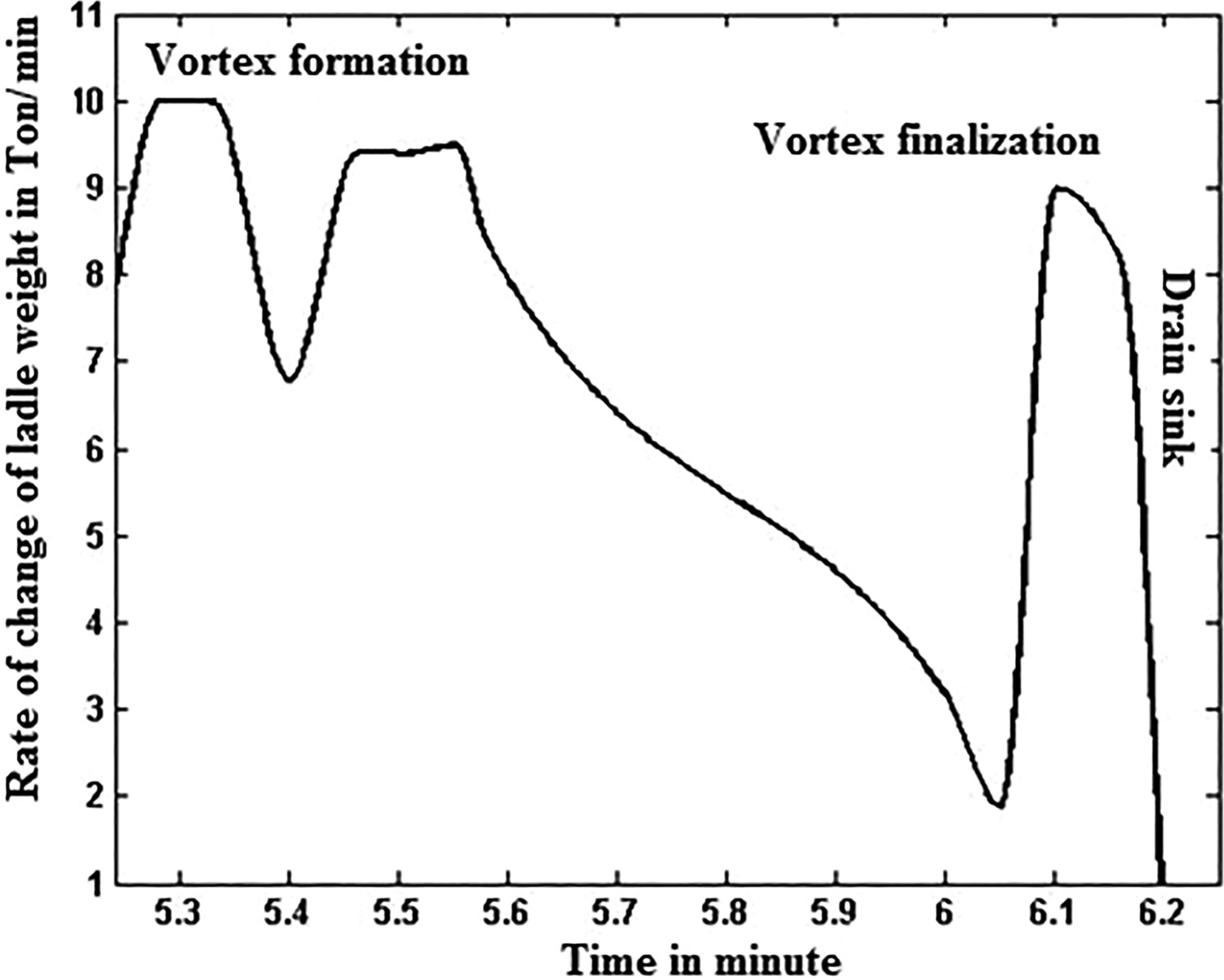
Figure 4 shows the time average variation of the standard deviation along with the variation of standard deviation (obtained from ROI2) and mean intensity (obtained from ROI1). It can be seen from Figure 4 that the time average of the standard deviation shows a rising trend before a sharp increase of the mean intensity. Thus, the position of the Y-axis cursor of the time average variation of standard deviation should be chosen in such a way that as soon as the time average variation of the standard deviation value crosses the cursor position, a signal is generated to initiate the movement of the slide gate. The slide gate can be moved towards partial closure or closure and opening in quick succession to diminish the effect of vortex formed inside the ladle. As a result, the sharp increase in light intensity may not be obtained at the same time as it would have been obtained in the absence of slide gate movement. As shown in Figure 3, the setting of the Y-axis cursor for mean gray level intensity and the time average variation of the standard deviation of the respective plot of the multiplot of Figure 4 should be carried out judiciously. The setting of the Y-axis cursor for generating a control signal to initiate slide gate movement can be correlated with the change in weight of the teeming ladle obtained from the load cell. Mazzaferro et al. [23] carried out the experimental and numerical analysis of the ladle teeming process with the help of a water model and concluded that under industrial conditions slag carryover occurs only due to drain sink formation. Figure 5 shows the typical rate of change of weight of a 150 Ton teeming ladle showing the formation of vortex sink and drain sink when there is 50 Ton material left in the ladle. Considering that slag carryover occurs only due to drain sink formation, if control signal is generated just before the onset of the drain sink when the slag and liquid steel flows at a speed of around 9 Ton min−1, a significant amount of slag can be stopped from entering the tundish. The estimation presented in Figure 5 is only an indicative one, subject to the change in ladle construction parameters and product mix. Results of the processing. The red line shows the sharp increase in the mean intensity, the white line shows the variation in Standard Deviation and the green line shows the time average variation of Standard Deviation. Typical rate of change of ladle weight of a teeming ladle.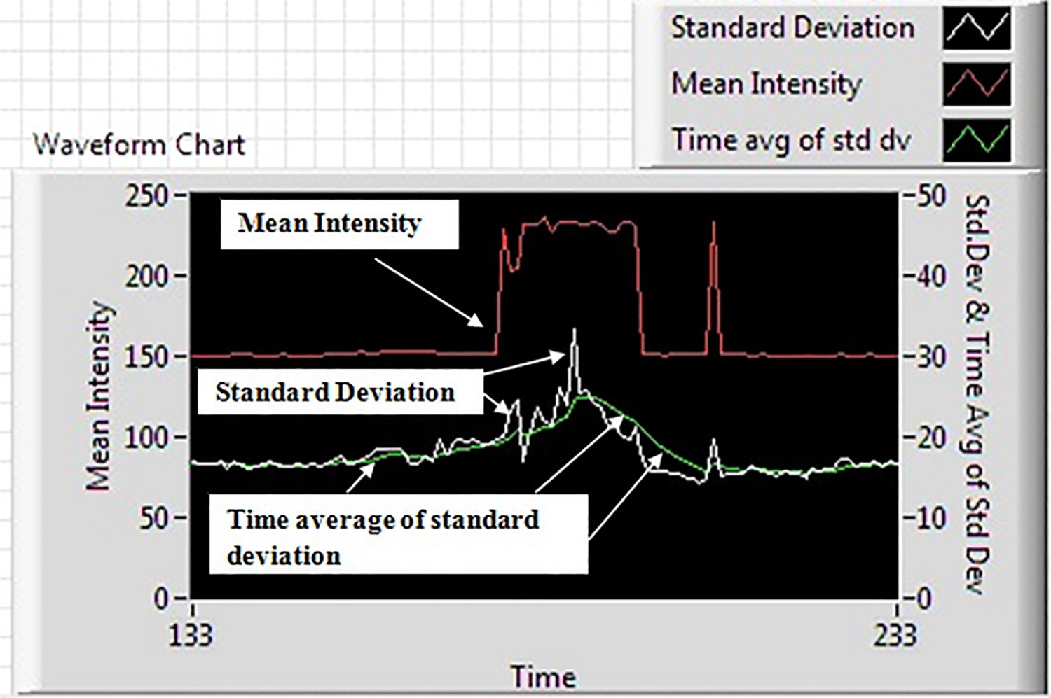
It is important to point out at this stage that undulation of tundish slag layer does take place due to argon shielding of the shroud. The argon gas shrouding is practised to prevent reoxidation of liquid steel near the slide gate region since reoxidation and air-pickup were found to be responsible for the formation of micro inclusions which result in quality issues of the finished product. During tapping from ladle to tundish through shroud, argon gas is injected through the side duct of the shroud to minimize the air ingress. The argon bubbles get aspirated inside the tundish and flow down with the liquid metal stream. At the point where buoyancy forces overcome the inertial forces, the bubble reverses the flow direction and starts to ascend. These ascending bubbles drag some amount of liquid metal towards the surface and the recirculating liquid sweeps off the slag layer radially and create an exposed region of liquid steel, known as Tundish Open Eye (TOE). The formation of TOE is highly detrimental as it causes nozzle clogging and defeats the purpose of using ladle shroud and argon shielding. Chatterjee et al. [24] showed that a higher flow rate of the argon generates strong recirculatory flows at the top surface which leads to higher values of surface velocities and larger TOE sizes. The authors recommended to practise tundish operation under the critical flow rate of argon. Chatterjee et al. [25] stated that various plants employ different techniques of argon shielding and the most appropriate one is yet to be established. Usually, plants practice steady casting which requires calm tundish bath and well-covered flux during tapping. This is obtained by employing argon gas with a uniform flow rate below the critical value throughout the tapping period. The absence of steady casting during slag carryover may lead to slag disintegration and formation of slag droplets. Zhang et al. [9] showed some improvements in shroud design that leads to steady casting with minimum surface turbulence. The ripples with small amplitudes appearing in the standard deviation curve before the sharp change in mean intensity curve due to light splashing are shown in Figure 4. This signifies slag layer undulations due to the interaction of ascending argon bubbles with the slag layer and transfer of energy and momentum from bubbles to slag during steady casting. The time average of standard deviation also does not show any significant change during this period of steady casting. The rising trend of the time average of the standard deviation appears when the amplitude of the undulation of tundish slag layer indicated by the standard deviation curve increases due to slag carryover.
Conclusion
Detection and control of slag flow from ladle to tundish in a casting operation is an important step towards cleanliness of the steel production. For this purpose, a vision-based system is developed based on the detection of light splashing. The major limitation of this method is that a significant amount of slag already enters the tundish due to the increased flow rate at the end of the tapping before light splashing takes place. This work has successfully developed a method to overcome this problem by detecting the surface undulation of the tundish slag layer. This vision-based detection process of the slag layer undulation is a significant value addition to the previously published work [16]. There is an increased trend in the amplitude of the slag layer undulation before a sudden brightening of the slag surface. If such undulations are identified by image analysis technique, control signal can be generated to move the ladle slide gate to limit a significant amount of slag flow into the tundish. The control signal from the processing computer to the plant PLC for slide gate movement can be sent through the output port of a DAQ card connected to the processing computer. If the generation of control signal can be correlated with the rate of change of ladle weight, it would be convenient to fix the Y-axis cursor position of the time average of standard deviation after several trial runs to accrue maximum benefit.
The effectiveness of the detection depends on the position of ROI2 for calculating the standard deviation. The Y-axis cursor position for mean intensity variation (obtained from ROI1) can only be decided after fixing the cursor position for the variation of time average of standard deviation. The decision for partial closure or the closure and opening of the slide gate in quick succession depends on the detection of vortex or drain sink along with the state of tapping, i.e. whether the tapping is at its end and the level of molten metal in the tundish. The developed system would help to improve the quality of the steel that is produced by continuous casting.