
Abstract
In order to enable the steel companies to achieve carbon peaks and carbon neutrality, the f-CaO content in steel slag should be reduced. For this reason, this study investigates the interface reaction evolution of the quicklime and different slag in the ‘iron’ slagging route of the CaO-FetO-SiO2-MgO system at the converter steelmaking temperature. The microstructure of the reaction interface was observed by an electron microscope. The results showed that the interface reaction formed CaO-FeO solid solution, (Ca, Mg) olivine phase, and 2CaO·SiO2. The change in thickness of CaO-FeO and (Ca, Mg) olivine shows a clear trend with the change in slag components.Therefore, the dissolution mechanism of quicklime in the slag was discussed, and the liquid phase mass transfer coefficients in different slags were obtained. The results will provide a theoretical basis for the faster dissolution of lime in slag and reduction of f-CaO content in slag.
Introduction
In the converter steelmaking process, to enhance the efficient use of lime, thereby reducing the residual f-CaO in the steel slag, and achieving the purpose of steel slag recycling, it is necessary to make the dissolution of lime into slag quickly and completely. Steel slag is one main byproduct of steelmaking, and a large amount of steel slag accumulation will influence the environment. For the purpose to protect the environment, reducing pollutant emissions, and promote the construction of ecological civilization, solemn goals, and commitments are proposed by President Xi Jinping at the 75th United Nations General Assembly that ‘Striving to reach the peak of carbon dioxide emissions by 2030, and strive to achieve carbon neutrality by 2060’. Furthermore, the acceleration of green and low-carbon development is also included in the 14th Five-Year Plan. In order to achieve carbon peak and carbon neutrality, the iron and steel industry should be arranged in advance to provide carbon emission space for other emerging industrial sectors. Because it is the upstream industry in the industrial sector and the largest carbon emitter (accounting for about 16% of China’s total carbon emissions). At present, the steel industry’s carbon peak target is initially set to achieve a carbon peak by 2025, and reduce carbon emissions by 30% from the peak in 2030 [1,2]. To achieve this goal, it is necessary to further increase the comprehensive utilization rate of bulk industrial solid waste such as coal gangue, fly ash, industrial byproduct gypsum, smelting, and chemical waste residues. Among these, the comprehensive utilization rate of iron and steel smelting slag needs to reach 95% above. So it is particularly important to improve the comprehensive utilization rate of steel smelting slag.
The undissolved lime makes the steel slag rich in f-CaO and the volume expansion of the steel slag is a limiting factor for the low recycling rate of converter slag. For this part of f-CaO, it is necessary to enhance the dissolution behaviour of quicklime in the converter blowing process [3]. The dissolution rate of quicklime is related to the properties of quicklime itself and the properties of slag. In the converter ‘iron’ slagging route, the interface reaction between the slag and quicklime in the initial stage of smelting can well reflect the dissolution rate of quicklime. At present, much research has studied the dissolution rate of lime in slag. Russell [4] studied the activity of lime and its dissolution rate in CaO-SiO2-FeO slag and found that lime with high activity had a faster dissolution rate in slag. Deng et al. [5] compared the dissolution behaviour of lime in SiO2-FeO slag and CaO-SiO2-FeO slag and found that the dissolution rate of lime in CaO-SiO2-FeO slag was significantly slower than that in SiO2-FeO slag. Although there are many pieces of research on the dissolution phenomenon of lime in slag, first the interfacial structure evolution of slag and lime should be figured out to understand the influence factor of lime dissolution.
In this study, the evolution behaviour of interfacial structure between quicklime and converter slag was studied to clarify the mechanism of the slagging reaction of quicklime in the initial stage of the slag-forming route based on the FetO component.
Experiment
Preparation of experimental materials
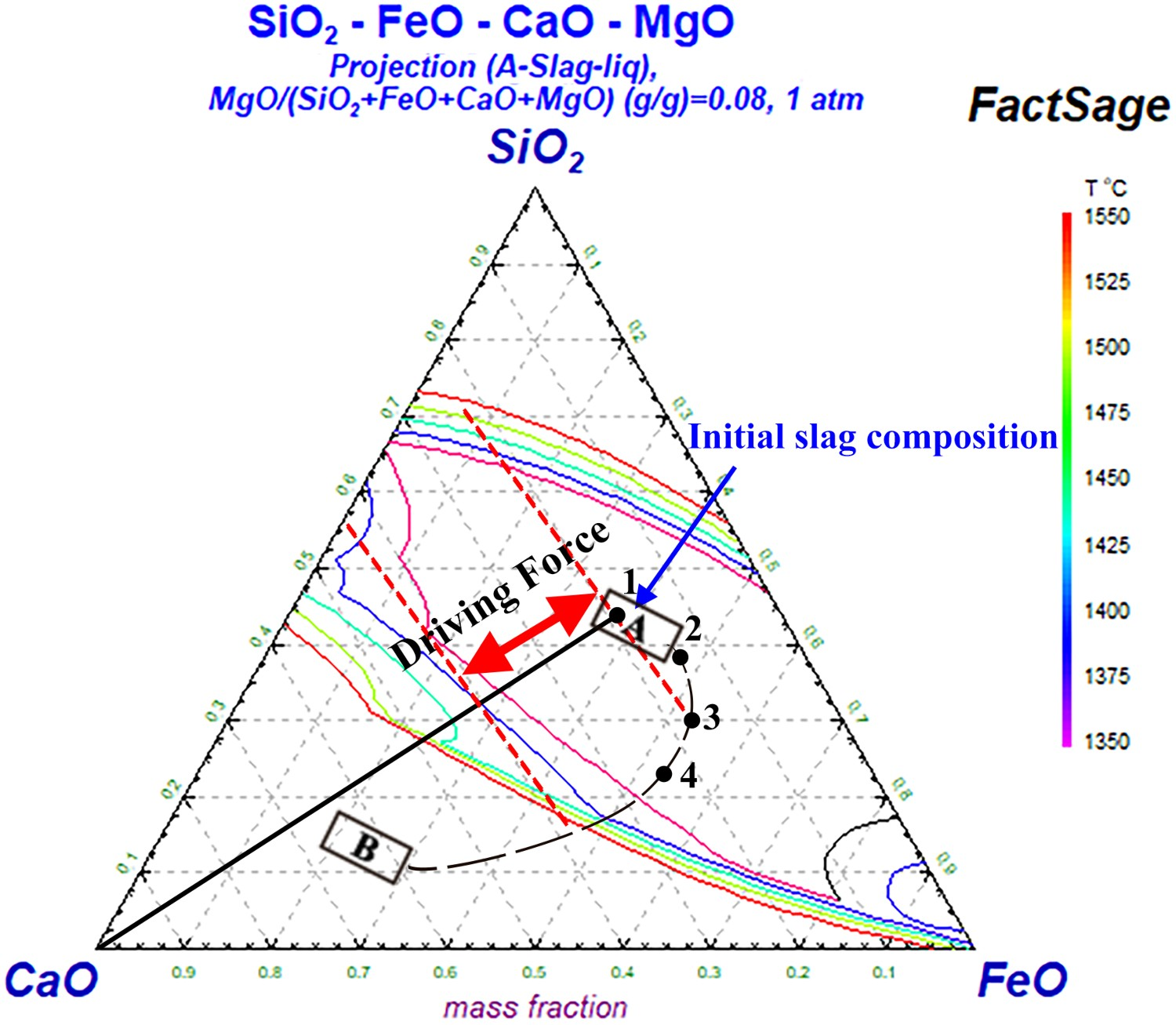
The raw material used in this experiment is the quicklime calcined in the laboratory, and the raw material is limestone which is provided by a steel company. The composition of limestone is determined by XRF analysis. The results showed that the main component of limestone is CaCO3, the content is as high as 98.55%, and it contains a small amount of MgO, SiO2, and other components. Combined with the analysis results of limestone X-ray diffractometer (model PHILIPS-Xpertpro) (Figure 1(a)), calcite (CaCO3) is the only mineral phase. Observing the microstructure of limestone by using a scanning electron microscope (Zeiss-ASIN EVO10, Zeiss, Germany), as shown in Figure 2, the limestone is mainly composed of CaCO3 crystals with a particle size of 10μm, which has a clear crystal structure. Further, limestone needs to be polished into a cylindrical shape with Ф:10 mm and h:15 mm. The limestone particles were washed and dried at 200°C for 3 h. After being cooled to room temperature, they are placed in a drying vessel for use. The slag system studied in this experiment is CaO-FetO-SiO2-MgO based slags. The synthetic slag compositions are shown in Table 1. CaO, SiO2, and MgO are chemically pure reagents, and FetO is added in the form of ferrous oxalate. The proportion of 100 g slag for each experiment. The corresponding points of the synthetic slag composition in the ternary phase diagram are shown in Figure 2. Mineral compositions of experimental raw materials: (a) limestone; (b) quicklime. The corresponding positions of synthetic slag B1-B4 in the quaternary phase diagram. The chemical composition distribution ratio of slag, mass%.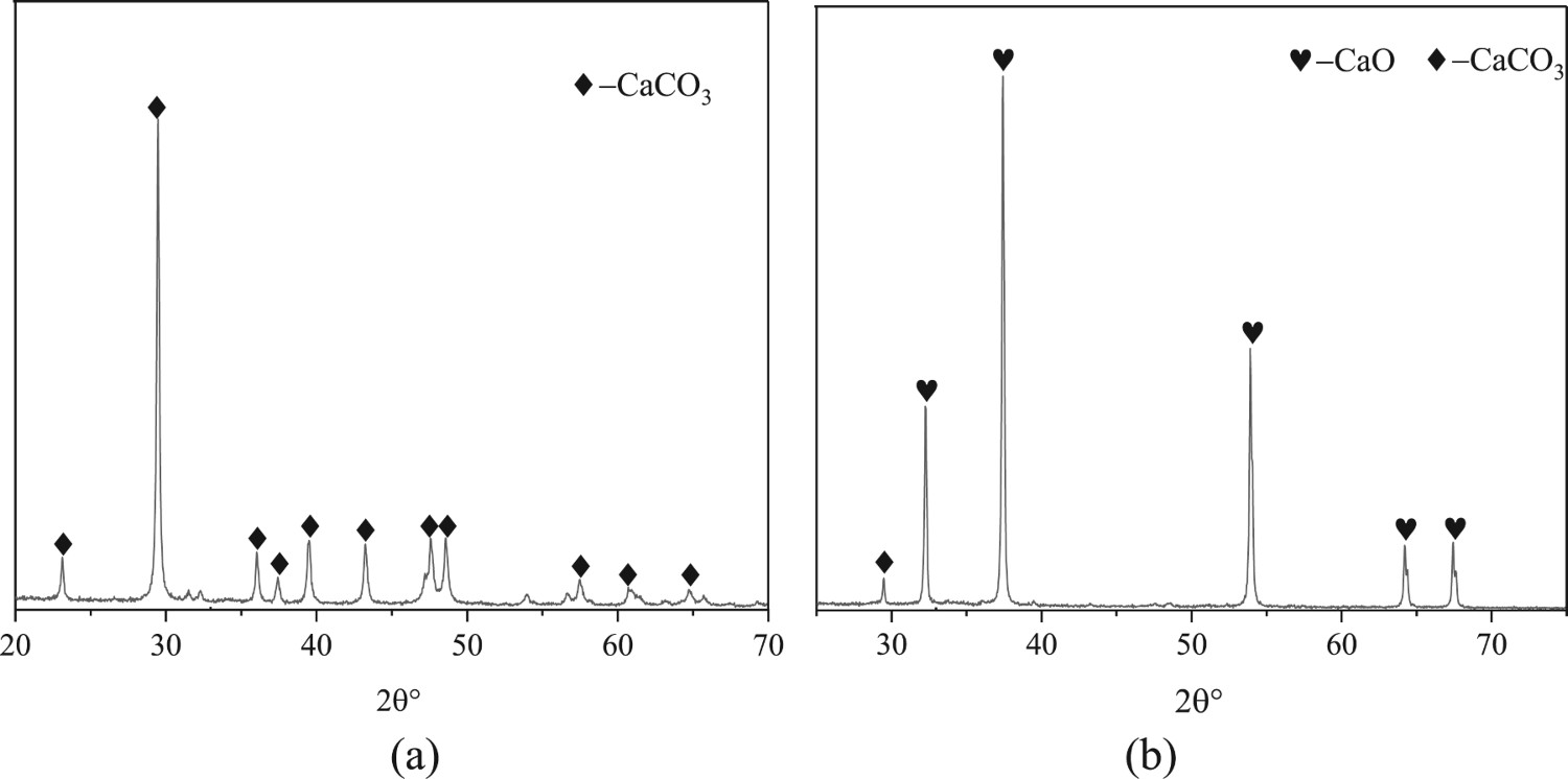
Experimental process
The experimental apparatus is schematically shown in Figure 3(a). The dried cylindrical limestone was placed into a basket woven from molybdenum wire. When the carbon tube furnace was heated to 1350°C under an atmosphere of high-purity N2. The Mo-wire basket was then put into the carbon tube furnace and stably calcinated in the isothermal zone for 10 min. After the calcination process was completed, the Mo wire basket should be taken out of the carbon tube furnace quickly with a hook that is made of Mo wire. The obtained quicklime (L0, The activity is 346.20 mL) was then put into a clean metal container and cooled to room temperature. The cooled quicklime will be placed in a closed container with a desiccant for later use. Experimental apparatus (a) Carbon tube furnace, (b) Experimental schematic diagram.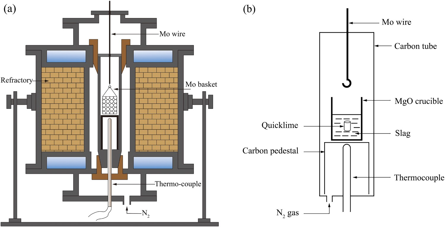
The specific process of the dissolution of quicklime in the slag is as follows. First, due to the different melting points calculated by FactSage 8.0 of synthetic slag samples B1-B4, which is about 1325°C, 1350°C, 1290°C, and 1450°C, respectively, so they were pre-melted at 1100°C, 1150°C, 1200°C, 1250°C for about 30 min to makes it better sintered, and then cooled to room temperature. The slag was broken and put into a MgO crucible (Ф51.5 mm*Ф41 mm*122 mm). Second, the crucibles were put into a carbon tube furnace and heated to 1400°C, 1400°C, 1400°C, and 1500°C with the furnace according to the heating system(the flow rate of high-purity N2 is 3–4 L min−1, and the heating rate is 10°C min−1), respectively. While it was completely melted, the prepared cylindrical quicklime was then put into the slag with a spoon that was made of Mo wire.
The schematic diagram of this dissolution step is shown in Figure 3(b). The quicklime was dissolved for the 90s in the slag, then the lime and slag were taken out and cooled to room temperature. The diameter before and after the dissolution of quicklime was dissolved was measured with an electronic vernier calliper with an accuracy of 0.01 mm. The cooled slag sample was cut into two halves, half of which was partially inlaid with a mounting machine, ground, polished, and cleaned by an ultrasonic cleaner. Finally, it was dried in a vacuum drying oven and then sprayed with gold for preparation. Scanning electron microscopy was used to observe the microstructure of the reaction interface between quicklime and slag. For the remaining slag sample, 1–2 g slag sample was taken and ground into a powder with a particle size of <325 mesh, which is used for XRD analysis.
Analysis and detection methods
For the collected samples, according to the metallurgical lime physical inspection method YB/T 105-2005, the intelligent lime activity detector HT-102 (Android Kechuang) was used to determine the reactivity of the sample, and the scanning electron microscope (Zeiss-ASIN EVO10, Germany) was used to observe the microstructure of the sample and the equipped energy spectrometer (EDS, Oxford X-Max80) was used to determine its micro-area composition. The X-Ray Powder Diffractometer (PANalytical) Analytical Instrument Company, Netherlands, XPert PRO MPD was used to determine the phase of the sample, and the ImageJ software was used to measure the thickness of each phase layer in the slag.
Experimental results
Evolution behaviour of the interface between quicklime and slag
When the quicklime was added, the slag first reacted with the surface of the quicklime. Then it penetrated into the pores and cracks which were generated on the surface of the calcined quicklime at a high temperature. As a matter of fact, it caused slag to continue to diffuse which made the quicklime dissolve [6–10]. Figure 4 presents the microstructure of the dissolution reaction interface between quicklime and slag B1-B4. The interface microstructure of dissolution reaction of quicklime in slag B1-B4 corresponds to (a–d).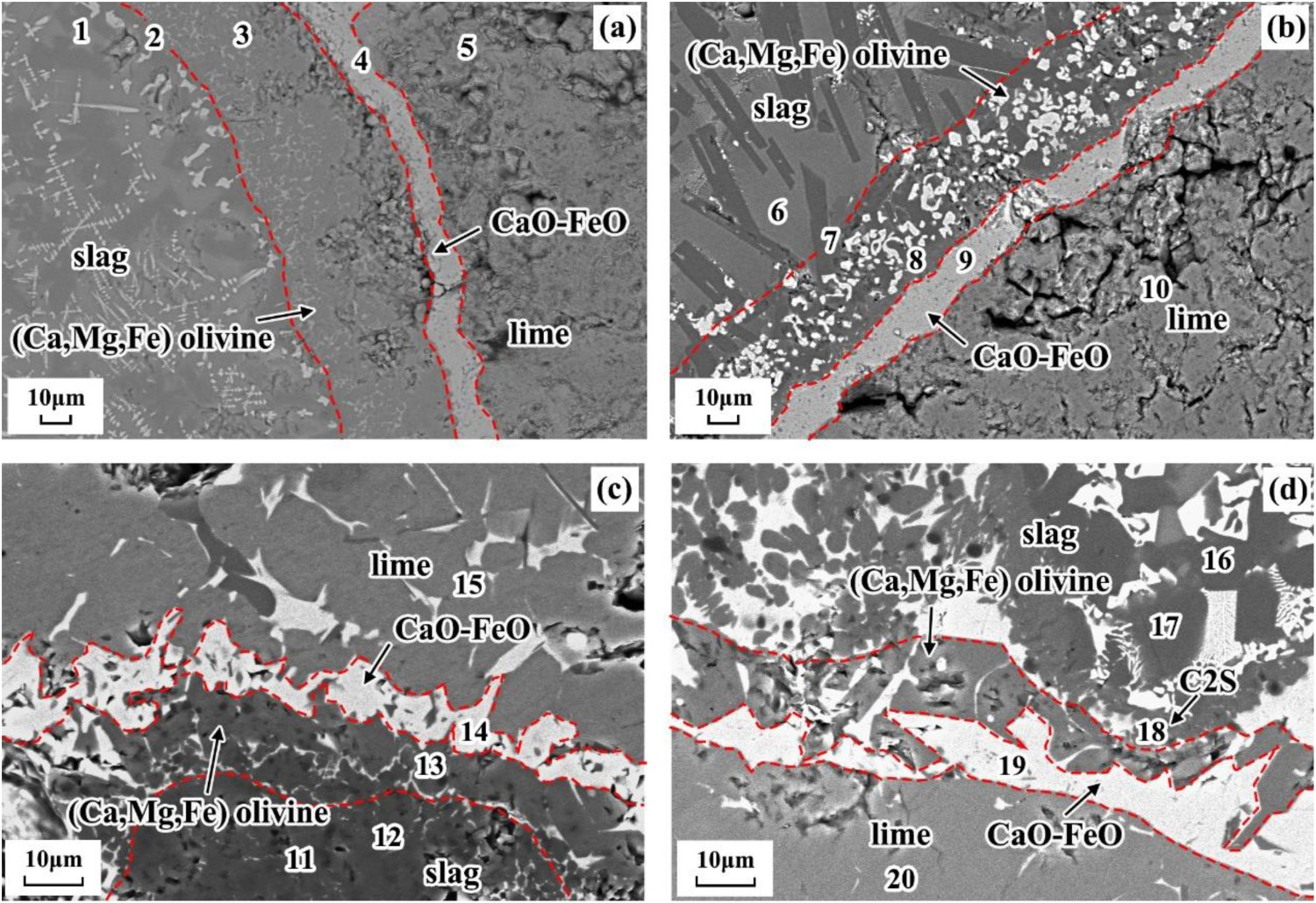
As shown in Figure 4(a), it can be seen that there was a continuous CaO-FeO solid solution layer at the reaction interface between lime and slag. Note that the thickness of the solid solution layer is about 15–20 μm, and the slag has obvious stratification. Moreover, the stratification is a Ca,Mg,Fe) olivine phase layer with a thickness of 37–70 μm. As shown in Figure 4(b), the continuous CaO-FeO solid solution layer formed in B2 slag became thicker than that of B1, and the thickness is about 5–20 μm. On the other hand, the Ca,Mg,Fe) olivine phase layer is reduced to about 27–45 μm thick. It should be mentioned that it also contains a large amount of RO phase such as FeO and Fe3O4 which were precipitated at high temperatures at the same time. As a matter of fact, it can be seen in Figure 4(c) that the thickness of the continuous CaO-FeO solid solution layer is reduced to 8–12 μm compared with B1 and B2. At this time, the thickness of the Ca,Mg,Fe) olivine phase layer is reduced to 9–15 μm, and the thickness distribution is not evenly. At the same time, there were some solid solutions began to form in the lime as the reaction interface of quicklime and B4 presented in Figure 4(c).
On the other hand, the transfer of interfacial substances will be accelerated because the fluidity of the slag becomes better, and therefore the reaction between the (Mg,Fe) olivine layer and CaO is also accelerated, so the (Mg,Fe) olivine phase layer also becomes thinner to 4–10 μm. The SEM-EDS dotting results are presented in Table 2 and the place of which is shown in Figure 4. Dot 18# presented in Figure 4(d) shows that a new phase is formed in the reaction layer of B4 slag, that is, 2CaO·SiO2(referred to as C2S in the text). Whereas it did not form a C2S layer. The average thickness of each phase layer was calculated according to ImageJ. Figure 5 presents the average thickness of the calcium-magnesium silica phase layer produced by the reaction of quicklime and slag in the converter, the average thickness of the calcium-magnesium silica phase layer is continuously reduced from 53.62 to 7.21 μm. The overall thickness of the CaO-FeO solid solution layer shows a decreasing trend, which is reduced from 15.87 to 8.27 μm. Variation of the thickness of each phase layer during the reaction between quicklime and slag B1-B4. EDS Dotting composition results of reaction interface, wt-%.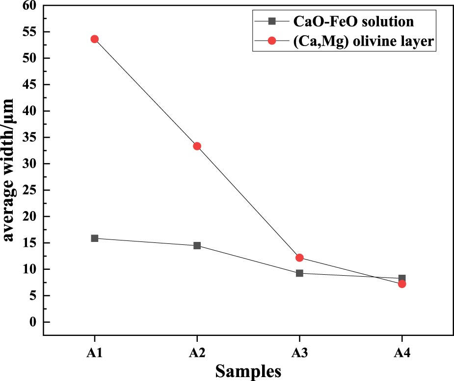
Evolution behaviour of converter slag properties
The microstructures of synthetic slag samples B1 through B4 with different composition ratios are shown in Figures 6(a) through (d). The lance position used in the converter ‘iron’ slag formation route is high-low-high, and B1 is roughly similar to the slag composition in the initial stage of converter smelting, which is point 1 in Figure 1. At this time, the newly added quicklime began to dissolve, and the content of FetO and SiO2 in the slag was high. Microstructure of synthetic slag B1-B4 corresponds to (a–d).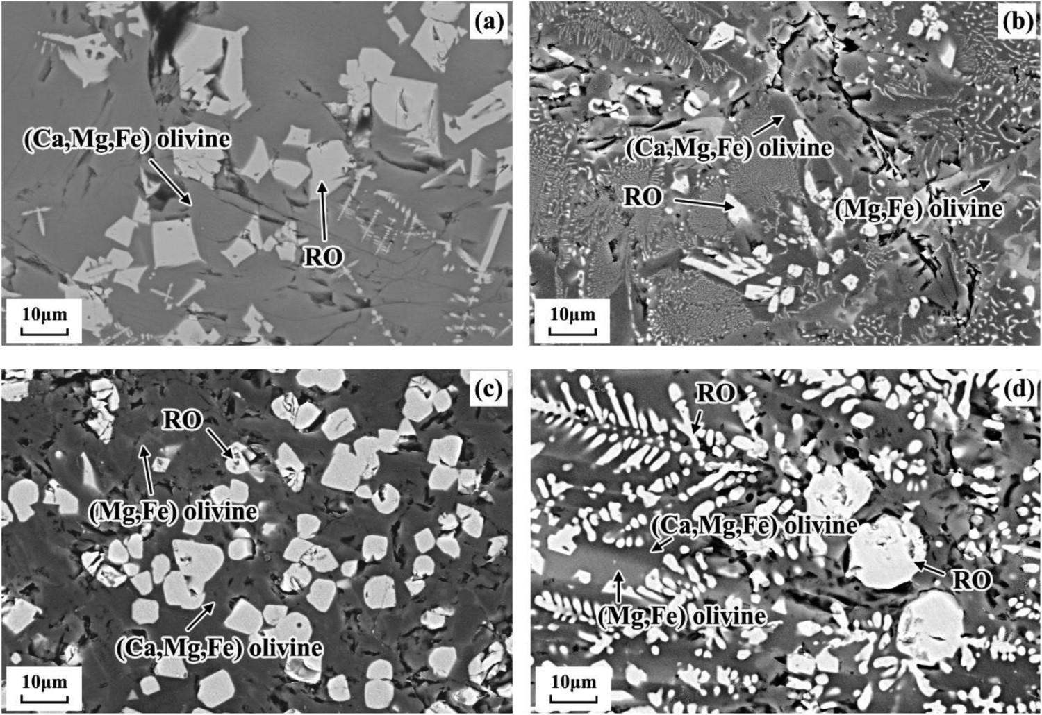
The XRD results obtained are summarized in Figure 7. They show that the main phase of B1 is (Ca,Mg,Fe) olivine, that is CaO·(MgO, FeO)·SiO2. It is worth noting that B1 also contains part of the RO (FeO, Fe3O4) phase which is precipitated at high temperature as shown in Figure 6(a). When the alkalinity is low and the FeO content in the slag is high, CaO in the olivine phase is easily replaced by FeO to form (Mg,Fe) olivine, that is (FeO, MgO)·SiO2. Therefore, the diameter of the RO phase in B2 is then reduced as presented in Figure 6(b). On the other hand, it is shown in Figure 6(c) that the (Mg,Fe) olivine phase in B3 is decreased due to alkalinity increased, and the precipitated RO phase also decreased. However, the grain size of the RO phase is larger than that of B2. As the alkalinity the content of FeO continued to increase, the FeO in B4 of which alkalinity is the largest continued to be replaced by CaO to form the (Mg,Fe) olivine phase and RO phase. Since the precipitated RO phase in B4 is the most at high temperatures as shown in Figure 6(d). Moreover, the RO phase formed before continues to grow, so the RO phase in B4 has the largest particle size. Crystallization mineral phase composition of synthetic slag samples with different composition ratios.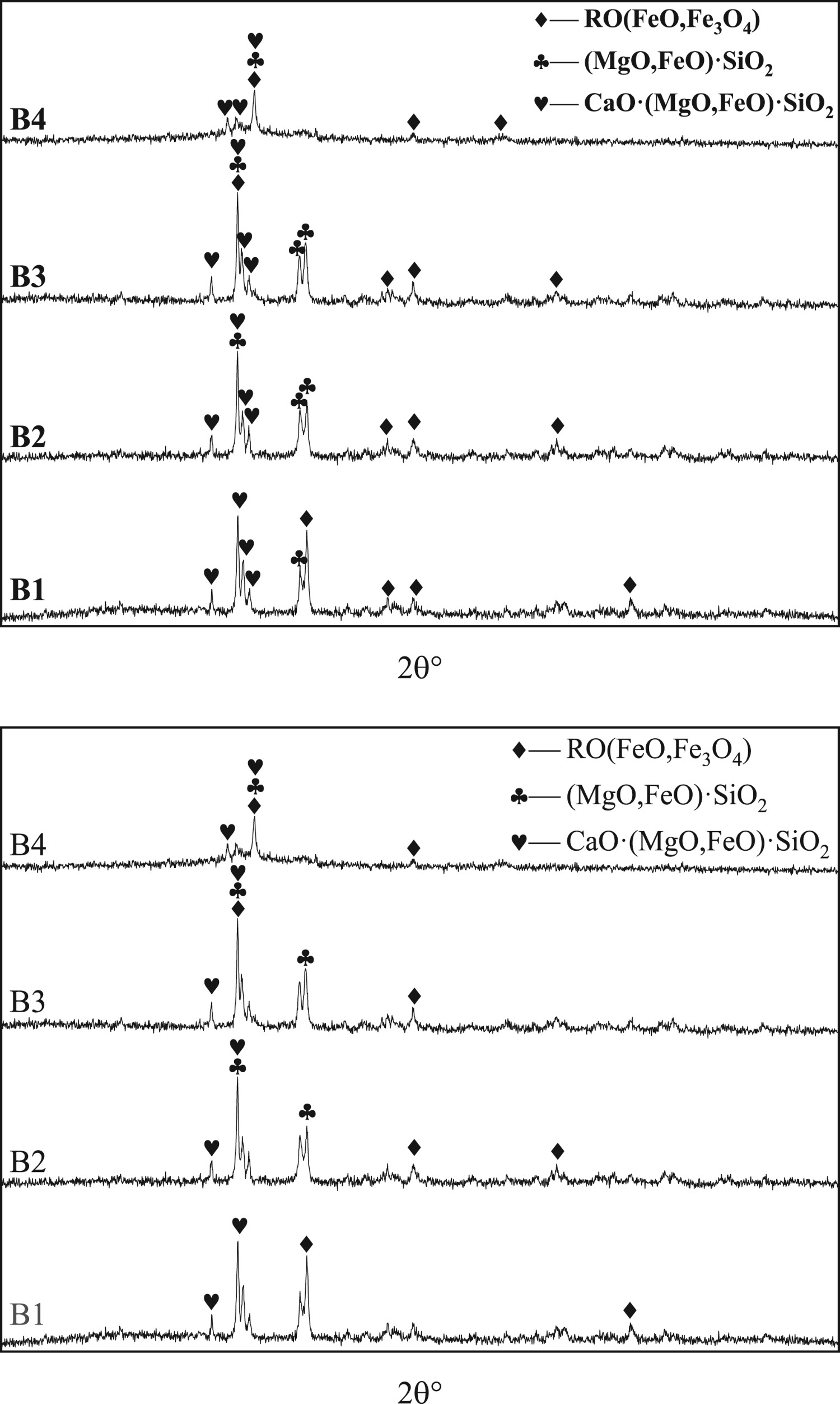
Discussion
Dissolution mechanism of quicklime in molten slag
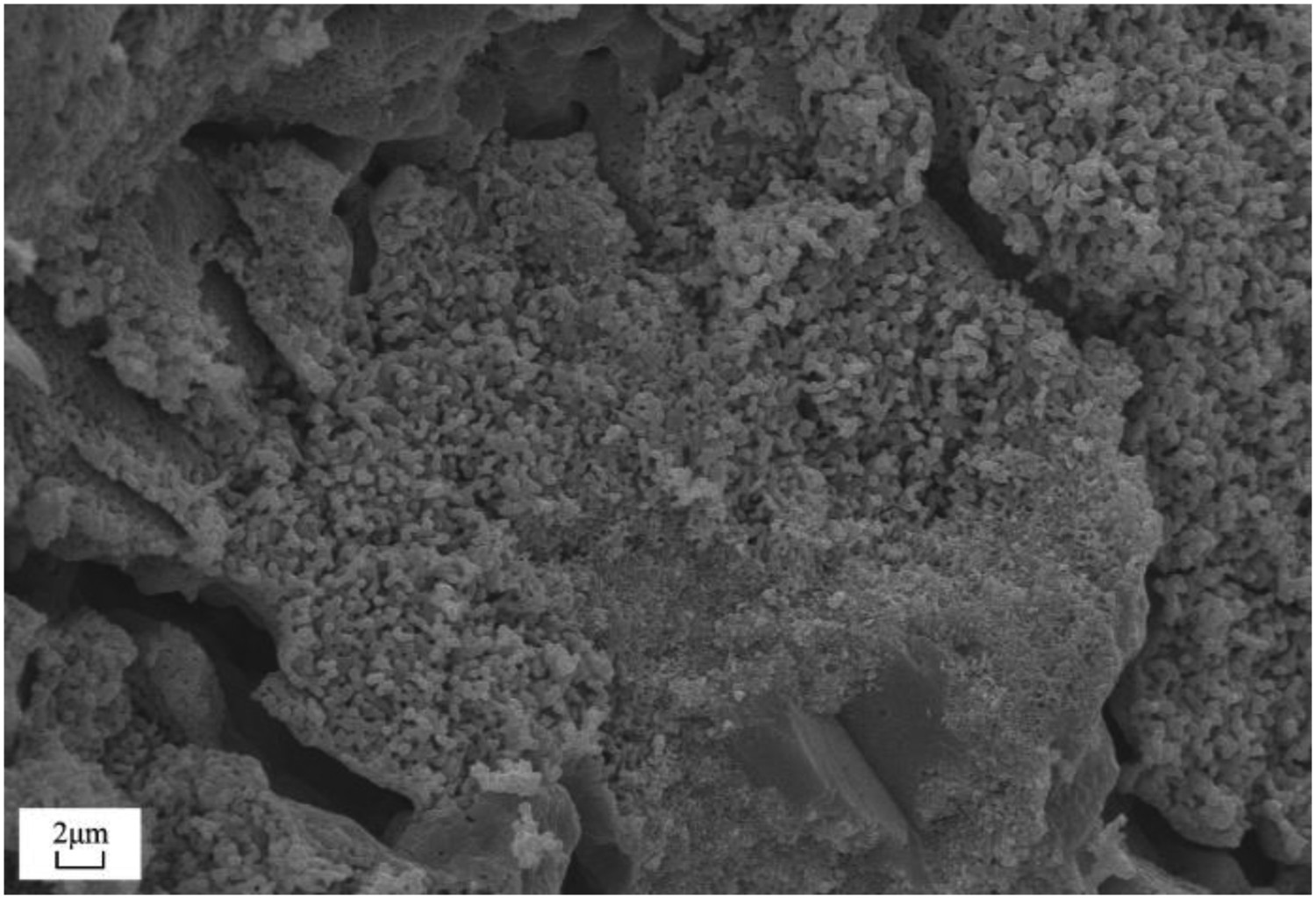
The diagram of the dissolution of quicklime in the slag is schematically presented in Figure 8. During the smelting process, quicklime is added. When the steel slag contacts the quicklime surface, an interfacial chemical reaction occurs. The microstructure of quicklime is shown in Figure 9. It can be clearly observed that there are many pores and cracks. Then the steel slag spreads into the quicklime along the cracks and small pores produced by calcination [11–17]. Schematic diagram of quicklime dissolution process in converter slag. The microstructure of quicklime by calcination.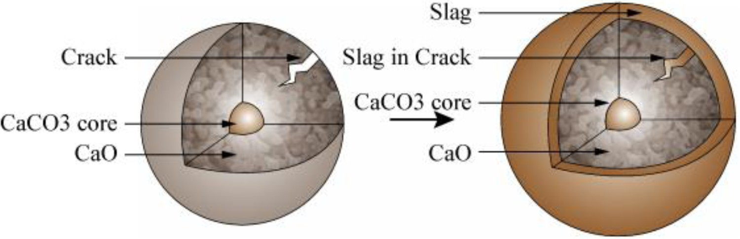
After the interface reaction occurs, FeO and SiO2 in the slag will penetrate into the quicklime from the slag, and CaO will diffuse from the quicklime surface to the slag. Since the diffusion rate of FeO is greater than that of SiO2, FeO first penetrates into the quicklime and reacts with CaO to form a solid solution of CaO-FeO, and then continues to diffuse into the quicklime. The SiO2 is blocked by the CaO-FeO solid solution due to its slower diffusion rate.
At this time, the CaO-FeO solid solution becomes the restrictive link for the diffusion of SiO2 into the quicklime. Since the content of SiO2 in the initial slag of the converter is relatively high, and enough CaO is provided by the continuously formed solid solution layer to react with the SiO2, so the slag will continue to produce a low-melting magnesia wollastonite phase [18–20]. The chemical reaction formula of the process is as follows:


The high-low-high blowing mode is adopted in the ‘iron’ slagging route, so the carbonization rate of steel slag is slow, and the FeO content in the slag keeps increasing. Moreover, the initially added quicklime has begun to dissolve, the CaO content in the slag then begins to rise, thus more CaO-FeO solid solution is formed. Owing to this, more SiO2 reacts with a solid solution to form slag, then the Ca,Mg,Fe) olivine phase layer is continuously reduced.
Figure 10 presented the surface scanning images of the reaction interface of lime and slag B2. It can be obviously seen that the Fe content in the CaO-FeO solid solution layer is the hisghest, followed by the content in the slag phase, and less in the olivine phase. In addition, two concentration gradients from slag to olivine phase and CaO-FeO solid solution layer to lime are formed. Owing to the concentration gradients that FeO diffuses from the slag and the solid solution layer to the olivine phase and lime, respectively. Moreover, CaO diffuses from lime to olivine and slag phases through the solid solution layer because of the high CaO content in lime. As shown in Figures 4(c,d), the solid solution began to participate in the CaO phase. This can be logically discussed that the reason is FeO content is high in the slag and it diffuses more easily through the cracks produced by the calcinated quicklime than SiO2. Note that during this period, the FeO content in the slag was close to the peak, and the CaO content was the highest. Owing to the increase of the FeO content, the viscosity of the slag decreases, so that the slag penetrated into the quicklime more easily. However, the thickness distribution of the CaO-FeO solid solution layer becomes discontinuous because the uneven cracks on the quicklime surface make the FeO penetrate unevenly. Surface scanning images of the reaction interface between lime and slag B2.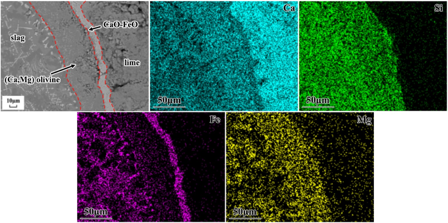
With the increase in smelting temperature, the FeO content in slag reaches a peak. At this time, low lance blowing started. When SiO2 diffuses into the quicklime, part of CaO will react with SiO2 to form various silicates. In addition, MgO will continue to be replaced by CaO in the calcium-magnesium silicate phase to form solidus C2S, so C2S is formed when SiO2 leaves the CaO surface. The melting point of C2S is very high, 2130°C, and the structure is dense. So that the dissolution of quicklime will be hindered by the formation of a dense layer of C2S on the surface. However, the CaO-FeO solid solution layer rich in FeO formed between C2S and quicklime makes it difficult for the C2S layer to adhere to the surface of quicklime, so there is not much C2S formed near the surface of quicklime. This helps the dissolution of quicklime and reduces the residual lime in the slag.
Dissolution kinetics of quicklime in molten slag
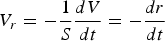
Cylindrical quicklime with a radius of r and a height of h is adopted in this study. Its volume V and wall surface area S can be expressed by the following Equations (5) and (6) [21]:

The dissolution rate of quicklime in the slag 


Diameter change of the 90s when quicklime is dissolved in synthetic slag with different composition ratios.
The liquid phase mass transfer coefficient can be obtained by formula (8) derived by Matsushima et al. [15], namely: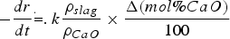
Among them, 

Mass transfer factors in synthetic slag with different composition ratios.
Conclusion
In the initial and mid-term of the converter iron slagging route, the reaction interface between quicklime and slag has two layers, that is CaO-FeO solid solution layer and the Ca,Mg,Fe) olivine phase layer from quicklime to slag, respectively. The formation of solidus C2S occurs in the mid-term slag. A CaO-FeO solid solution layer and a Ca,Mg,Fe) olivine phase layer are formed at an initial stage. As the FeO content in the converter slag increases, quicklime continuously reacts with FeO in the slag to form a solid solution and a Ca,Mg,Fe) olivine phase layer. In the middle of the slag, CaO will react with the SiO2 which remains on the reaction surface during the inward diffusion to form C2S. In the CaO-FetO-SiO2-MgO system in the early and mid-term slag, the mass transfer coefficient of CaO in the slag is obtained by calculation which is 0.007, 0.007, 0.011, 0.020 mm s−1 in slag B1-B4, respectively.
Footnotes
Acknowledgements
This work was financially supported by the National Natural Science Foundation of China (51974210, 52074197), Hubei Provincial Natural Science Foundation (2019CFB697), and State Key Laboratory of Refractories and Metallurgy, Wuhan University of Science and Technology.
Disclosure statement
No potential conflict of interest was reported by the author(s).