
Abstract
The wire-feeding spheroidization treatment is important research and how to realize visual control of the process is an unsolved problem all along. In this work, an improved model of cored wire-feeding spheroidization coupled with more proper boundary conditions was developed, in which both the heat transfer effect of Mg-core and steel shell are considered. In our simulation, an implicit time integration scheme was given in the framework of FVM to ensure the convergence of calculations. The reliability performance of the presented model was verified by comparing it with the test of the artificial insertion method. Particularly, the relationship among the temperature of the iron melt, the speed of wire-feeding and melt-explosion depth of cored wire was investigated using our model. In addition, we also study the temperature variation rules at different positions of the cross-section of cored wire, and the effects of parameters on the microstructures and properties of ductile iron could provide theoretical guidance for industrial production.
Highlights
The proposed improved simulation modelling of the heat transfer problems with complicated boundary conditions. Implicit time integration scheme and mesh subdivision in the framework of FVM numerically ensured stability and accuracy. A detailed study of the dynamic heat transfer characteristics of the feeding process in the iron melt considered the effects of interfacial heat transfer on the temperature field. Investigated the effects of parameters on the microstructures and properties of ductile iron. The model has high reliability, which is validated by the data obtained from the experiment.
Introduction
Spheroidal graphite cast iron is a competitive engineering material with excellent performance [1–3]. In the production process, the treatment of wire-feeding spheroidization may directly affect the internal quality and mechanical properties of materials [4,5]. The common treatment methods in industrial production include the flushing method, tundish-cover, plunging magnesium under pressure, rotary ladle processes, wire-feeding method and so on [6–8]. Among them, the most traditional approach is the flushing method, which is simple and operates easily, but it has some shortcomings, such as a low absorption rate of magnesium, large environmental pollution and a low degree of automation. With the rapid development of the cast iron metallurgical technology, high demand has been put forward on the casting quality, energy saving and emission reduction of ductile iron, which has driven the casting industry to carry out innovative technology continuously. For this reason, the wire-feeding method was developed, which was originally used as an advanced deoxidation technique of molten steel [9,10]; it has the advantages of high efficiency, automation and energy saving, and has been widely applied in cast steel production [11–13].
In recent years, lots of studies on heat and mass transfer behaviour of cored wire in liquid steel have been done [14–16]. Terrail et al. [17] simulated the process when the cored wire is immersed in molten steel by proposing a finite volume model. Sanyal et al. [18] adopted a finite difference approach with a fully implicit scheme to simulate the interaction when the cored wire was injected into the molten steel bath. It has been concluded that the molten slag on the surface of molten steel almost has no obvious impact on the melting behaviour of cladding wire. Castro-Cedeno et al. [19] presented a 1-D FVM numerical model, focusing on simulating the thermal behaviour when an aluminium cored wire is immersed in molten steel. Huang et al. [20] established a three-dimensional gas–liquid multiphase model to simulate the mixing efficiency in an argon-stirred ladle and studied the impact factors on the evaporation depth. Xiao and Zhu [21] did an in-depth systematic analysis and experimental research on the feeding process of the aluminium wire. These studies have laid a good theoretical and technical foundation for the quality improvement of molten steel metallurgy, and provided guidance for the intelligent control of the wire-feeding process [22,23]. Surprisingly, it has not been the case for feeding cored wire in the iron melt, where studies on numerical work and experimental are still rare now.
The wire-feeding method has been promoted in the field of iron melt due to its unique technical advantages, and from a practical viewpoint, the business communities have continuously optimized the spheroidized cored wire, the wire-feeding equipment and the method used in the spheroidizing process. At the same time, Shao et al. [24] performed a numerical simulation on the pretreatment process of fluid flow and considered the influence of mixing patterns, stirring speed and immersion depth on the fluid flow field. Chang et al. [25] used the ANSYS software theory to calculate the feeding speed that agrees with the results applied in the factory. However, feeding spheroidization in iron melt tends to have a big chilling tendency and high hardness and its metallurgical quality still has a significant gap compared with the flushing method. The reason may be ascribed to the weak research on complex boundary treatment of spheroidization. To the best of our knowledge, there is little study on numerical simulation and theoretical calculation in iron melt regarding the shell–core structured wires. It is difficult to monitor the change of thermos physical properties of the cored wire in real-time. Therefore, how to operate the feeding process intelligently and visually has become an urgent problem.
In this paper, the thermal physical phenomena of the feeding process in molten iron are considered. First, we established a three-dimensional axisymmetric transient heat transfer model for tracking the melting of the cored wire during its injection into the iron melt. Meanwhile, the separation scheme of the control equation with complex boundary conditions was derived based on the FVM. Moreover, the reliability performance of our model has been verified by the experiment of the artificial insertion method. To quantitatively reveal the mechanism of how the various factors affect the heat transfer behaviour of cored wire, the regression equations among the temperature of the iron melt, speed of wire-feeding and melt-explosion depth of the cored wire were obtained. Finally, to further represent the heat transfer behaviour when the cored wire is injected into the iron melt, the time-dependent characteristics of three feature points of a typical cross-section were extracted. Under the optimized parameters of the model, the effects on the microstructures and properties of ductile iron were investigated. The main objective of this paper is to provide significant theoretical and technical support for industrial production.
Mathematic model coupled with complex boundary conditions
In this section, in order to consider the complex heat transfer characteristics in the wire-feeding spheroidization, an improved model is presented under the boundary conditions between Mg-core and steel shell.
Physical background
The process of feeding spheroidization is mainly divided into two stages: the unsteady heat transfer in the initial stage and the steady heat transfer in the stable stage. The initial stage is the process when melt-explosion loss speed Vφ and wire-feeding speed V 0 tend to balance, which lasts for a short time. When Vφ = V 0, it enters a stable phase until the spheroidization process is completed. Therefore, the in-depth study of the heat and mass transfer behaviour in the initial stage has important theoretical significance for understanding the physical properties of the spheroidizing process.
The position and calculation area of the spheroidized cored wire in the iron melt is shown in Figure 1(a), when the spheroidized process is in the initial stage. We can see from the figure that the diameter of the upper part of the liquid pool The initial stage of feeding spheroidization (a): Cored wire in iron melt; (b): Local detail enlarged from part A.

Since the heat transfer model is axisymmetric of the cored wire, the calculation area and heat exchange interface displayed in Figure 1 are simplified and calibrated. As shown in Figure 2, the symmetry axis of the cored wire and the symmetry centre of the liquid pool is Boundary 1. Boundary 2 is the contact surface between the magnesium core and the steel shell. Boundary 3 is the contact surface between the steel shell and the iron melt. And Boundary 4 is the contact surface between the bottom of the magnesium core and the iron melt. Boundary 5 is the contact surface between the cored wire and air, in which the cored wire does not enter into the iron melt. Boundary 6 is the contact surface between the iron melt and the air, and Boundary 7 is the interface between the iron melt and the cladding. Calculation area and heat transfer interface (a) Contact boundary of the cored wire; (b) Contact boundary of the iron melt.
During the numerical simulation, some simplified hypotheses were drawn as follows:
(1) The chemical composition and temperature of the iron melt remain unchanged, and the physical parameters of the iron melt and the cored wire are isotropic in the process of heat transfer.
(2) When the cored wire is injected into the iron melt, the convection in the iron melt and its influence on the cored wire are negligible.
(3) Ignore the convective heat transfer between the iron melt and the spheroidizing ladle.
(4) The pure magnesium wire is in close contact with the steel shell wrapped outside.
Mathematical model
Heat transfer equation
The feeding spheroidization process is performed by an intelligent wire-feeding machine at a constant speed. It is completed by continuously feeding the cored wire into the iron melt. When the cored wire is injected into the molten metal pool with a constant velocity of V
0, the heat equation can be written in cylindrical coordinates (r-θ-z):


Since the cored wire has an axisymmetric structure, the heat transfer behaviour is nearly irrelevant to the angle parameter θ. So the governing equation of heat transfer can be simplified as follows:
Therefore, the heat transfer equation can be transformed to T (r, z; t). Both sides of Equation (2) are multiplied by r to avoid dividing by an infinitesimal amount when r is close to 0, and it can be rewritten as follows:
Furthermore, the vector form is expressed as follows: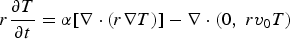
Boundary conditions
There are three types of boundary conditions during the heat transfer process when injecting a cored wire into iron melt [26], which are the symmetric Boundary 1, the contact heat transfer Boundary 2, Boundary 3, Boundary 4, and the radiation heat dissipation Boundary 5, as shown in Figure 2. The first kind is the axisymmetric boundary condition (Boundary 1),

The second kind of boundary condition may be represented as follows: Mg-core contacts with steel shell: (Boundary 2) Steel shell contacts with iron melt: (Boundary 3) Mg-core contacts with iron melt: (Boundary 4) Cored wire contacts with air: (Boundary 5)
The third kind of boundary condition is that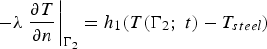
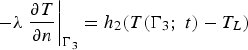
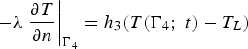
wherein ϵ is the radiative coefficient, h
1, h
2 and h
3 are the heat exchange coefficients, σ is the Stefan–Boltzmann constant, T
g is the ambient temperature, and T
L is the temperature of the iron melt.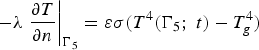
Initial conditions
The physical parameters of iron melt and cored wire are isotropic in the heat transfer process. Before immersion, the temperature of the cored wire T w = 29°C is uniform at t = 0. It is assumed that the temperature of molten iron remains constant throughout the immersion of the cored wire. Similarly, the temperature loss of iron melt in the period of computation is ignored.
Numerical computing methods
Owing to the irregular calculation area and complex boundary conditions in the calculation process, the finite volume method was used to numerically solve the problem of heat transfer. Especially in the implementation process, an implicit time integration scheme was given in the framework of FVM to ensure the convergence of calculations. The detailed processes were given as follows.
Mesh division and control volume
As the schematic diagram of meshing is shown in Figure 3 when using FVM in the state of feeding spheroidization, the specific division steps are as follows: Schematic diagram of grid division (a) Global graph; (b) Partially enlarged graph.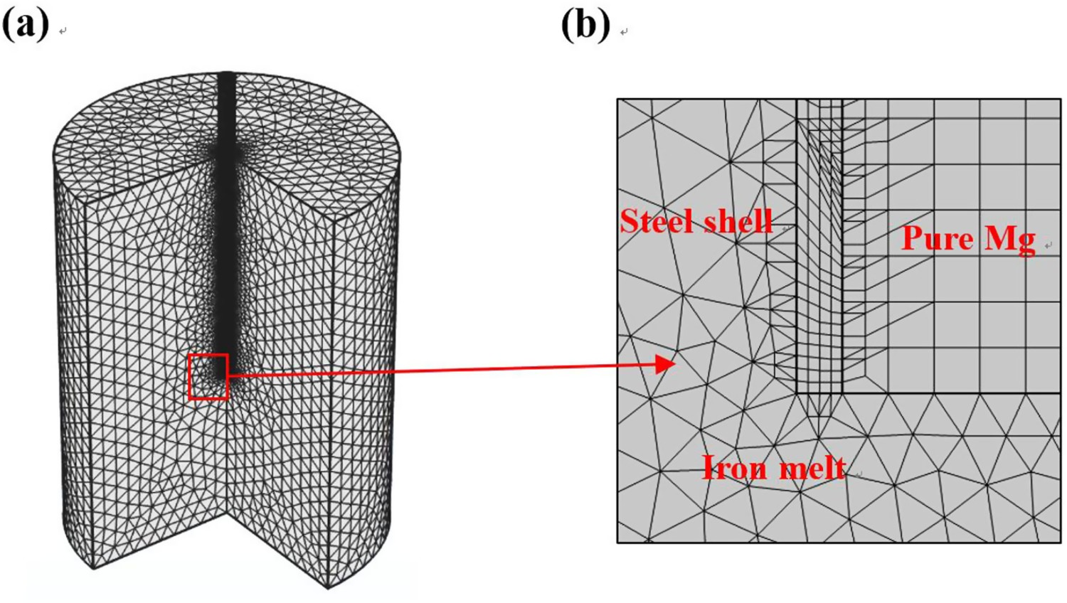
First, according to the size of the model, establish points at different positions. Then, connect the points into lines. Afterwards, construct a surface through the line to distinguish the determined surface from the line. And finally, divide the surface mesh by a quadrilateral grid. Figure 3(a) is the global graph of meshing. Figure 3(b) is the partially enlarged schematic of iron melt and cored wire. Make triangular meshe division for the computational domain to determine the mesh nodes. Meanwhile, as shown in Figure 4(a,b), the approximate points of the grid nodes and the control units of triangular elements are determined by dual subdivision [27]. Triangular mesh division in the computation domain. (a) Interior point dual subdivision; (b) Dual partition of the boundary point.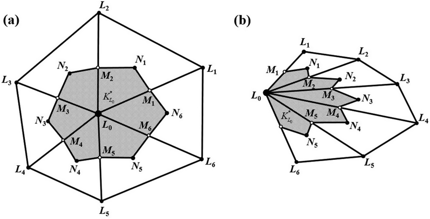
Integral transform of the governing equation
The integral transform of Equation (4) is an important step of the finite volume method, so the integral form is as follows: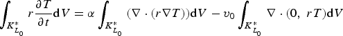
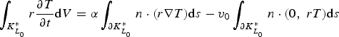
The left side of Equation (10) is the transient term, where 
Equation discretization
Since the integral formation is derived, the discretization of governing equation includes the transient, convection, and diffusion terms.
Transient term discretization
To discrete the transient term of the integral Equation (10) by forwarding a difference scheme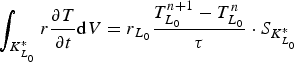


Convection term discretization
The discretization of the convection term should include the integration calculation on line elements and on dual units. Integral of line elements
For internal line elements M
1
N
1
M
2 in Figure 4(a), the implementation of integration is as follows: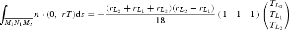
For the boundary line units, the heat exchange should be taken into consideration. Take L
0
M
1 in Figure 4(b) for the sample, so we get: Integral of the dual unit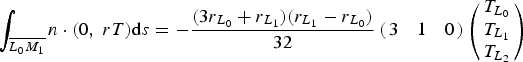
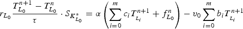
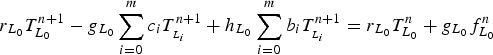
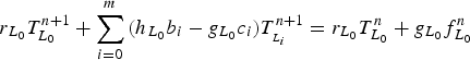
The integration of the convection term should conclude the interior point and the boundary point. As shown in Figure 4(a), all boundaries of the dual unit are internal line units, so the equation can be expressed as the integral sum of all boundary edges of the control volume: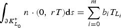
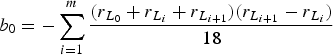

The dual unit in Figure 4(b) consists of boundary line units and internal line units. So, for boundary points, it can be obtained on the basis of Equations (12) and (13):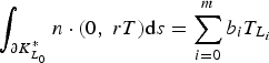
Similarly, bi
is the nodal temperature coefficient of 


Diffusion term discretization
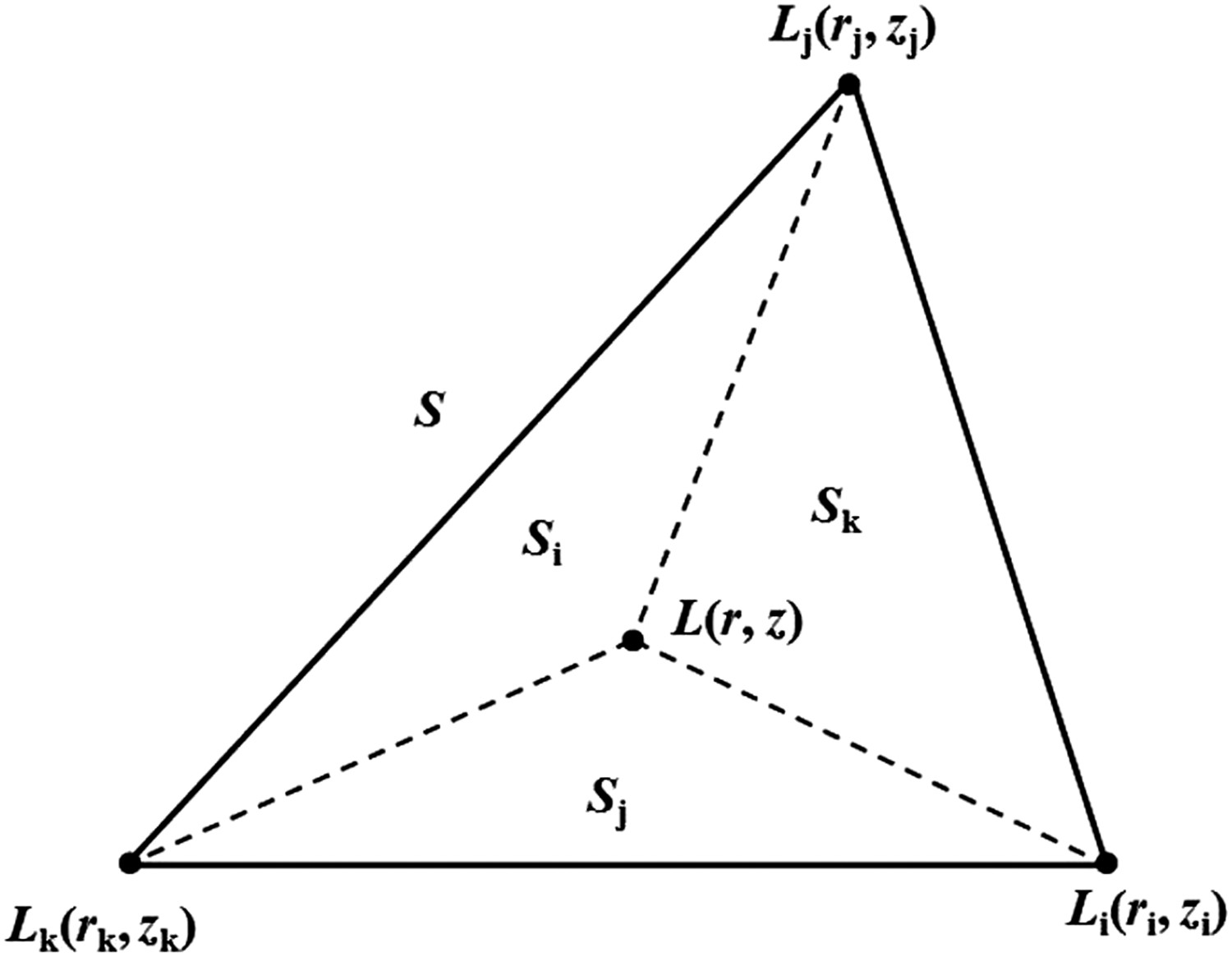
In order to obtain more accurate estimates, the area-weighted average evaluation method is applied. As shown in Figure 5, T(r, z) is the temperature of the node L(r, z) inside the triangular element, and it is estimated by interpolating the nodal temperatures Ti
, Tj
, Tk
at each mesh nodes Li
, Lj
, Lk
. Illustration of each point within the triangular grid.
Discrete format of the heat transfer equation
After discretizing the convection term, transient term and diffusion term, the discrete format of the heat transfer Equation (10) can be derived naturally. We also used the implicit time integration to ensure the stability of the calculation, the discrete equation for the internal node can be expressed: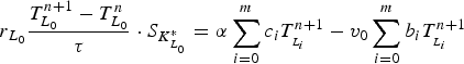
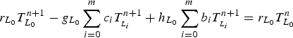
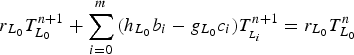
Here, 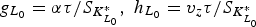
Matrix operation of discrete equation
Since the discretization schemes of governing equation were obtained, the matrix format can be expressed as follows:


Results and discussion
Thermophysical properties of materials
Physical parameters of the cored wire and iron melt [28].


Physical parameters of the cored wire varying with temperature [28].
In the experiment, a 5-tonne intermediate frequency induction furnace was used to melt iron, and a 1-tonne spheroidizing ladle was used during the spheroidizing process. First, pour the molten raw iron from the furnace into the
The chemical composition of the iron melt.
Experiments
In order to verify the reliability of the numerical simulation results, the artificial insertion trial of cored wire was carried out based on the theoretical calculation. The detailed transformation process is as follows: first, the spheroidized cored wire was inserted vertically into the iron melt to a certain depth at a constant speed, and then it was pulled out quickly. At the same time, the time is recorded when the cored wire enters the iron melt, and the insertion depth, speed and other physical parameters of the cored wire are calculated. The experimental steps include the following: Straighten the cored wire, and roughly determine its appropriate length by trial and error; Determine the origin and measure the initial distance L from the origin to the end of the cored wire; Test the melt temperature T; Insert the cored wire vertically along the centre of the liquid pool at a constant speed by manual operation, and accurately record the time difference Δt from the start of insertion to the end with a high-precision stopwatch; Measure the distance


The insertion speed V
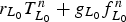
0 is calculated by the following formula:


At the same time, the function expression is obtained:
Dynamic heat transfer process of wire-feeding spheroidization
The effect of iron melt temperature
The effect of temperature on the melt-explosion depth is calculated theoretically at V0
= 32 m min–1, setting three levels of the temperature of the iron melt, 1460, 1480 and 1500°C. Figure 6 illustrates the evolution of heat transfer of cored wire during the solidification process at different temperatures of iron melt, where the blue area is the cored wire and the surrounding red area is the iron melt. It can be seen that melting will occur when the top end of the cored wire is at a certain depth. Subsequently, melt-explosion will occur when the temperature of the top end of the cored wire reaches the vapourization temperature of Mg. This is because the temperature of the iron melt is higher and the heat continuously transfers to the cored wire. And the melt-explosion depth of cored wire is also different from the change in the temperature of the iron melt. It is worth noting that under the a certain speed of wire-feeding, the melt-explosion depth decreases with the increasing temperature of the iron melt. The reason is that the heat transfers between the cored wire and iron melt increase with the rising temperature of the iron melt, and the time to reach the melting point of cored wire becomes shorter. Temperature nephogram of cored wires at different temperatures (V
0
= 32 m min–1) (a) T = 1460°C; (b) T = 1480°C; T = 1500°C.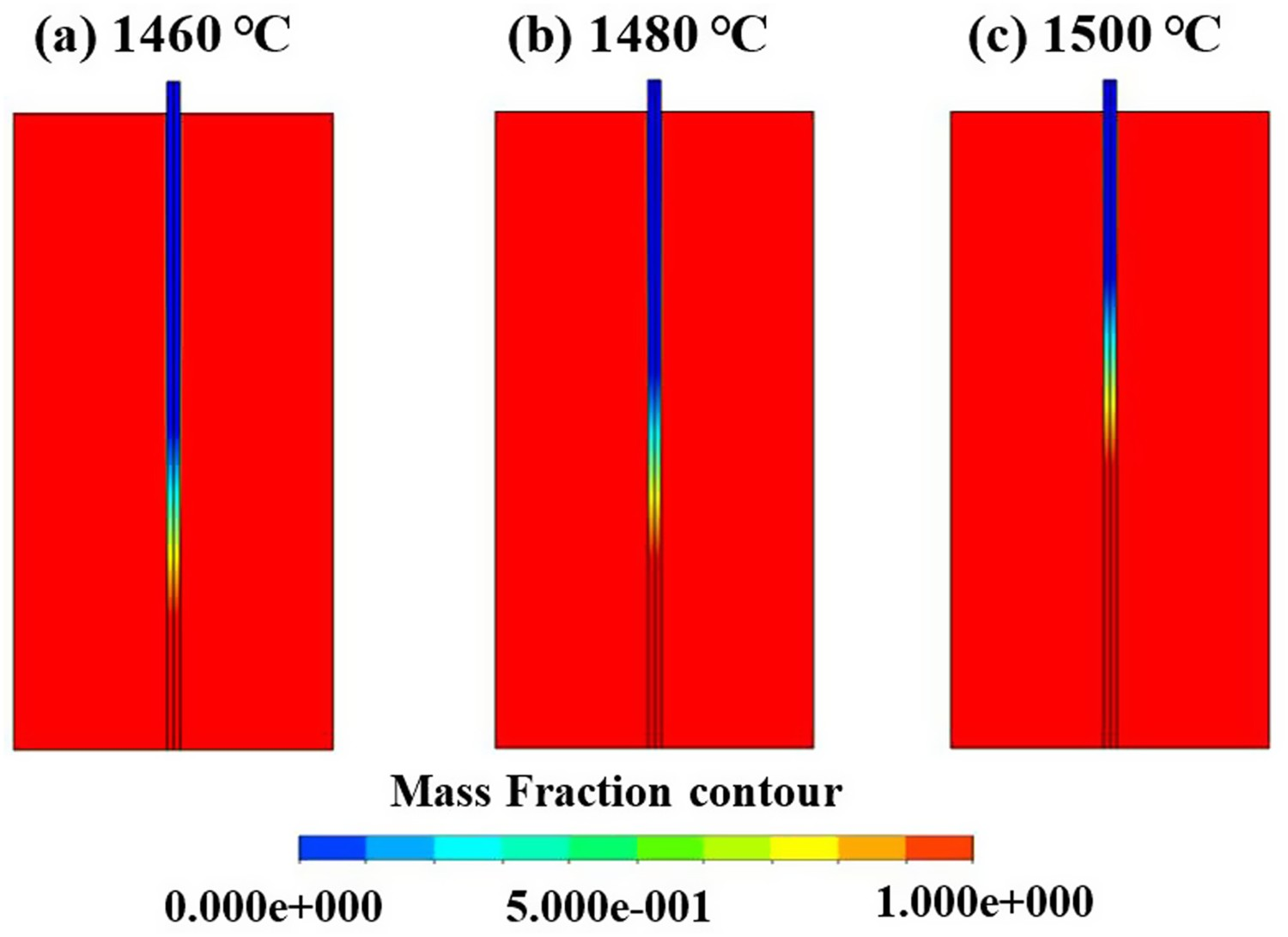
The effect of feeding speed
In order to explore the effect on the depth of melt-explosion that comes from the speed of wire-feeding, the speeds of 22, 27 and 32 m min–1 were studied when the temperature of the iron melt was 1480°C. Figure 7 shows the temperature nephogram of the cored wire under different speeds of wire-feeding. It can be seen that the depth of melt-explosion also increases with the increasing speed of wire-feeding. This is because at a specific temperature of the iron melt, as the speed of wire-feeding is higher, the difference in thermal diffusion rate is greater. Temperature nephogram of cored wires at different feeding speeds (T = 1480°C) (a) V
0 = 22 m min–1; (b) V
0 = 27 m min–1; V
0 = 32 m min–1.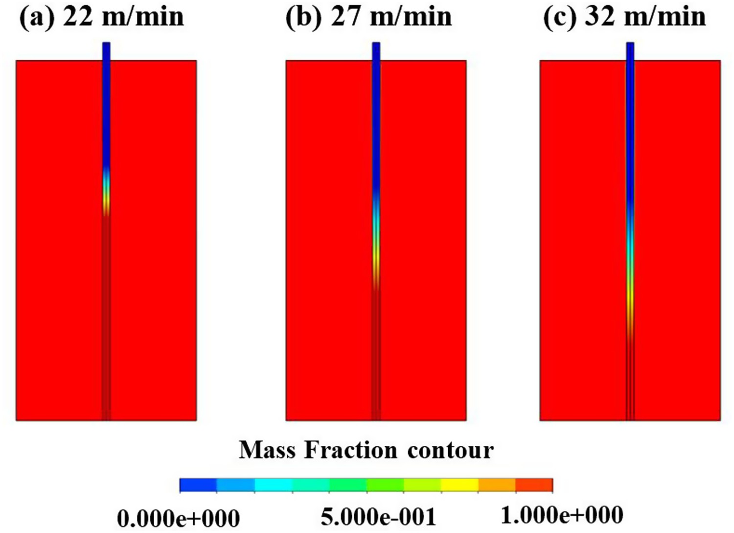
Analysis of heat transfer characteristics of the spheroidized cored wire
Figure 8 shows the temperature variation of three characteristic points (the centre of the steel shell, the centre of the cored wire, and centre of the radius of the cored wire) on the 100 mm section away from the top end of the cored wire. It can be seen that the steel shell has the fastest heating rate and the highest temperature, which is mainly related to the small thickness and low thermal resistance. However, the temperature at the centre and half of the radius of the cored wire is lower. On the one hand, as the thermal conductivity of the steel shell is small, when heat transfer is conducted from the steel shell to the magnesium core, the thermal resistance becomes larger with the decreasing radius. On the other hand, the thermal conductivity of liquid magnesium is larger, it rises with the increase in temperature, meanwhile, the sectional temperature is easy to homogenize. Temperature changes at different positions of the cross-section of the cored wire.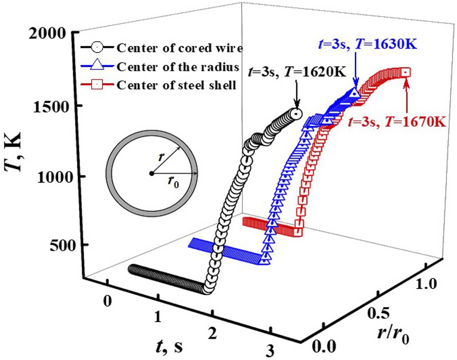
In the experiments, the heat transfer process between the iron melt and the cored wire starts at the top end of the cored wire. The intense heat exchange undergoes through the end surface and the side, which forms a large temperature gradient along the radial and axial directions, thus resulting in the rapid rise of the temperature in the centre of the cored wire. Owing to the large axial size, long heat transfer distance, and large thermal resistance, there is a big difference in the temperature nephogram. However, with the short size of the radial dimension, the small thermal resistance and the fast heat transfer, the radial temperature gradient is small.
Variation of melt-explosion depth with iron melt temperature and speed of wire-feeding
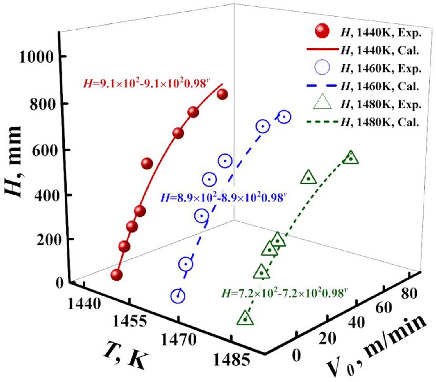
In order to fully understand the influence of parameters in the process of wire-feeding spheroidization, a systematic artificial insertion trial was carried out on the basis of theoretical calculation. Figure 9 shows the variation of melt-explosion depth with the speed of wire-feeding and temperature of the iron melt. It can be seen that the data obtained by the artificial insertion method are highly consistent with the curve of simulation results, which shows that at a certain temperature, the melt-explosion depth tends to increase as the speed of wire-feeding increases. And under a certain speed of wire feeding, the melt-explosion depth tends to decrease with the increased temperature of the iron melt. It is consistent with the following equation by means of multiple regression: Variation diagram of melt-explosion depth.
Analysis of variance.
Regression parameter.
Effects of parameters on the microstructures and properties of ductile iron
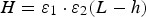
When the size of the spheroidizing ladle and the amount of iron melt are constant, the ideal melt-explosion depth is usually located at a certain height at the bottom of the ladle. At this point, the melt explosion phenomenon of cored wire begins and the path of magnesium vapour diffusion to overflow the liquid surface is the longest, which is conducive to maximizing the absorption rate of magnesium. Therefore, under the conditions of actual production, when the ideal melt-explosion depth H is constant, the linear relationship between the wire-feeding speed V
0 and the temperature of molten iron T can be obtained by Equation (35):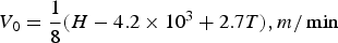
Usually, the spheroidization temperature of the iron melt is set at 1440–1480 °C. With the decrease of molten iron temperature, the absorption rate of magnesium increases. In this study, as the mass of molten iron is 1000 kg, the ideal melt-explosion depth H is 400–450 mm. Taking H = 400mm, for example, setting the spheroidizing temperature T = 1460°C, the feeding speed V
0 = 28 m min–1 can be obtained from Equation (36). The diagram of equal melt-explosion depth line can be obtained, as shown in Figure 10. Diagram of equal melt-explosion depth line.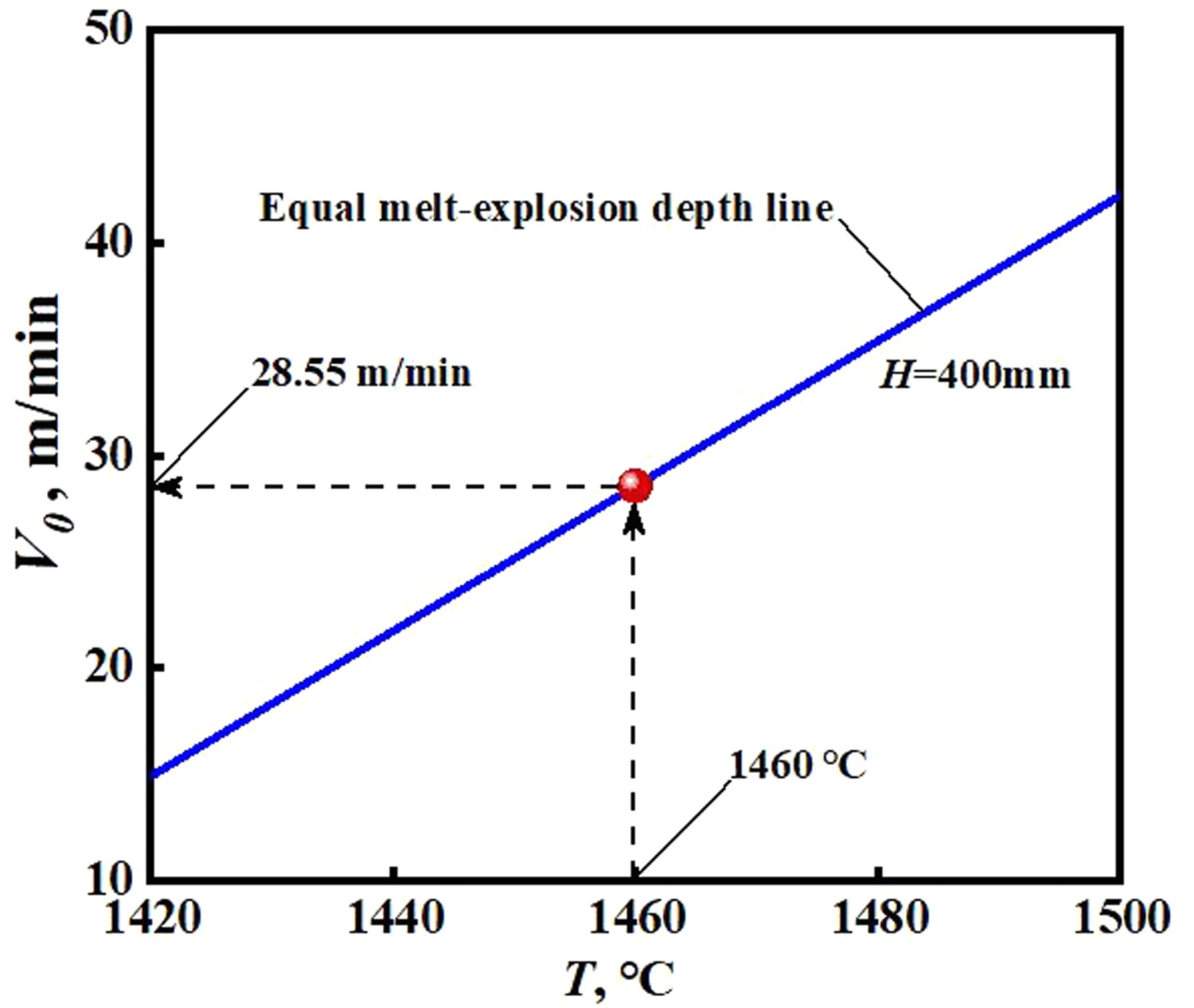
The length of the spheroidizing cored wire is determined by the content of sulphur in iron melt and the absorption rate of Mg after spheroidization, etc. It can be estimated by the following expression [29]: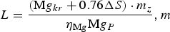


It can be seen that the existing theoretical model can be used to theoretically predict and accurately control the process parameters of feeding spheroidization, to meet the needs of industrial ductile iron production and provide strong technical support for high-performance ductile iron parts and batch stable production. Figure 11 shows the microstructure of ductile iron obtained under the spheroidizing parameters. Figure 11(a) is the graphite shape. Figure 11(b) is the basic organizational structure, which is composed of ferrite and pearlite. It can be seen the graphite spheres are round and uniformly distributed without eutectic carbides and other compounds. Table 6 shows the quantitative analysis results of microstructures and mechanical properties of ductile iron. The spheroidization rate of ductile iron is 85.6%, the amount of ferrites is about 80%, the tensile strength and elongation are 552 MPa and 10.8%, respectively, and the properties meet the material requirements of JS/450-410. Both simulation and experimental results indicate that the existing theoretical model can be used to theoretically predict and accurately control the process parameters of wire-feeding spheroidization, it can meet the industrial production needs of ductile iron, and provide strong technical support for high-performance ductile iron castings and batch stable production. Microstructure of nodular iron with feeding speed of 28 m min–1 at 1460°C (a) Graphite shape; (b) Basic organizational structure. Effects of parameters on the microstructures and mechanical properties of ductile iron.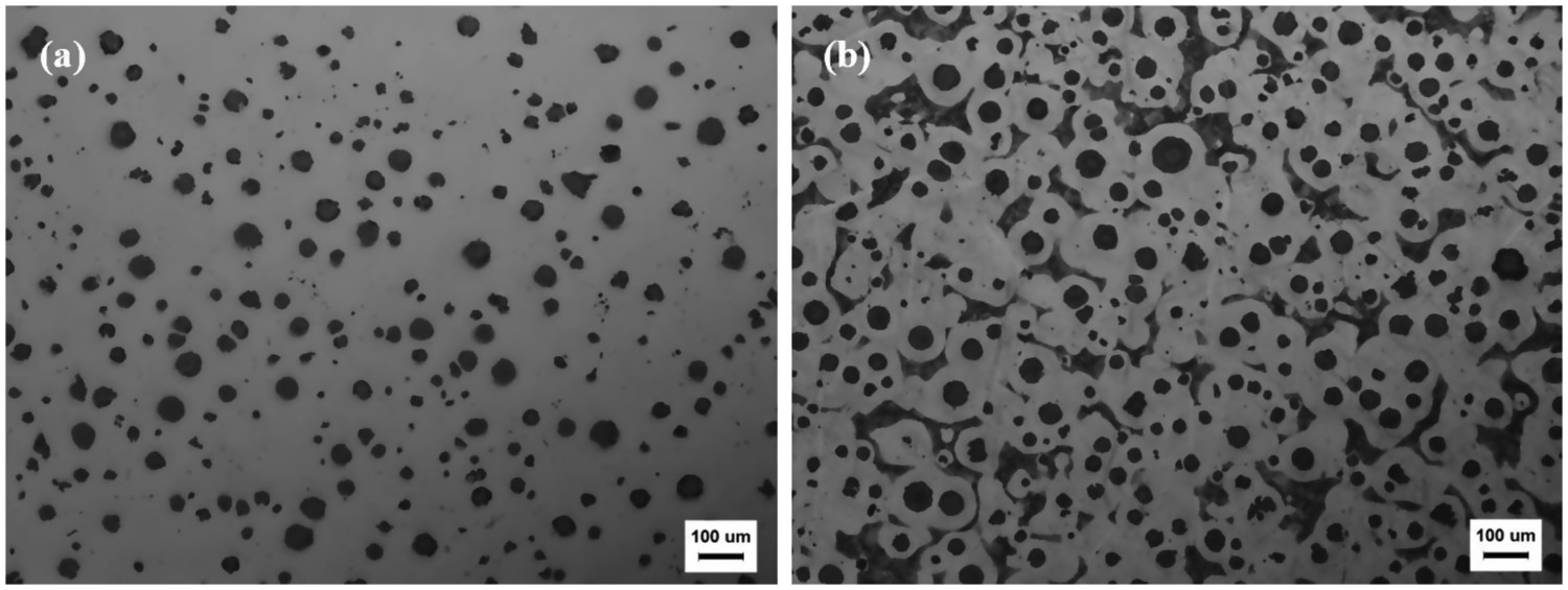
Conclusions
To quantitatively reveal the heat transfer regularity, a three-dimensional axisymmetric mathematical model of the unsteady heat transfer process has been described by numerical simulation accomplished with the finite volume method. We studied the thermal behaviour present during the cored wire injected into the iron melt. In our simulation, the implicit time scheme was used to assure excellentstability. The calculation results show that the simulated value of our presented model is highly consistent with the experimental results obtained by the artificial insertion trial. We also can numerically draw the following conclusions using our model.
(1) For a given insertion speed, the release depth of the core material is mainly determined by the total thickness of the steel shell and the temperature of the iron melt, and these factors are most difficult to control in industrial production.
(2) The melt-explosion depth is affected by the insertion speed and temperature of iron melt simultaneously; Under the constant feeding speed, the melt-explosion depth of cored wire decreases with the increased temperature of the iron melt. When the temperature of the iron melt is under a certain condition, the melt-explosion depth increases with the increased speed of feeding. Moreover, we also get the most optimal melt-explosion depth in the process of spheroidization.
(3) More interesting, the regression function was found to better understand the relationship among the temperature of the iron melt, the speed of wire-feeding and melt-explosion depth. Obviously, we also confirmed that the steel shell has the fastest heating rate and the highest temperature among three special points in cross-section.
(4) Finally, based on the optimized parameters, the effects on the microstructure and properties of ductile iron were studied, and the ideal results of the iron melt after spheroidization were obtained, as shown in Table 3. The spheroidization and ferrite rates reached 85.6% and 80%, respectively. The properties of the alloy meet the material requirements of JS/450-410.
Footnotes
Disclosure statement
No potential conflict of interest was reported by the author(s).