
Abstract
In this study, a novel thermo-mechanical controlled processing (TMCP) schedule, based on ultrafast cooling (UFC), was used to fabricate heavy gauge X80 pipeline steels for solving the low qualification drop-weight-tear test (DWTT) properties. The microstructures of the X80 pipeline steels were all composed of quasi-polygonal, acicular ferrite (AF), and granular bainite (GB) produced by Laminar Cooling (LC) and UFC. The grain sizes were finer and the average length of HAG was higher produced by UFC. The main strengthening mechanisms in LC-process steel were grain strengthening and precipitation strengthening, and dislocation strengthening. However, the main strengthening contribution in UFC-process was related to grain strengthening and dislocation strengthening. The decrease in strength induced by reducing Nb, Mo, and Cr contents in UFC steel was compensated by increasing the contribution of grain strengthening. In conclusion, the low-cost X80 pipeline steels can be produced by UFC without degradation of strength and toughness.
Introduction
To meet the increased delivery pressure in energy transportation, large-diameter, heavy-gauge, high-strength pipes are widely used to improve energy transport efficiency [1–4]. Strength and low-temperature toughness, good weldability, resistance to hydrogen-induced cracking, and excellent resistance to fatigue were the main critical properties required in these types of low-alloyed steels [5–7]. Therefore, studies on optimizing alloy composition design and modifying thermo-mechanical controlled process (TMCP) schedules are actively conducted for good-grade pipeline steels [8–10].
Up to now, for heavy-gauge X80 pipeline steel with a thickness of more than 22 mm, the weak cooling control capability of conventional TMCP equipped with a laminar cooling (LC) system caused negative effects on the microstructure [11,12]. The microstructure includes a lower fraction of acicular ferrite (AF) and coarser grains, especially in the heart position. This cooling technique and composition have led to a low qualification rate in controlling the drop-weight-tear test (DWTT) properties of pipeline steels. Therefore, it is a huge challenge for improving the DWTT properties of heavy-gauge pipeline steels. A previous study concluded that the fraction of AF and bainite ferrite (BF) has a decisive influence on the DWTT property of pipeline steel. A good DWTT property can be obtained when the AF fraction reaches 70% [13,14]. Compared with the conventional laminar cooling (LC) technique, the cooling capacity of ultrafast cooling (UFC) is higher, which is beneficial for the refinement of microstructure and further improves the mechanical properties, especially in the heart position [15,16].
Recently, various types of low-carbon micro-alloyed steel plates were fabricated by the extensive use of the UFC technique for reducing the alloy cost, improving the strength, and low-temperature toughness [17,18]. To improve the mechanical properties and reduce the alloy cost, the UFC technique was applied to process 520 MPa (X80) pipeline steel with a lower content of Ni and Mo. To apply the UFC technique for processing high-grade pipeline steel, the strengthening mechanisms are essential for the low-cost composition design and processing technique. However, limited research focuses on these critical issues. Thus, it is interesting to explore if the reduction in Nb and Mo contents in X80 pipeline steel can be realized by using the UFC technique without loss in strength and toughness. This aspect requires further systematic investigation here.
Therefore, the goal of the present work was to investigate the microstructure and strengthening mechanisms of Heavy Gauge Pipeline Steel with different Mo and Nb contents by different cooling routes. The evolution of precipitation states, grain characteristics and mechanical properties with different cooling routes are also described in this paper. The objective of this research was to provide experimental data and a theoretical foundation to produce higher-grade cost-reduction pipeline steel with high strength and toughness.
Experimental
The investigated were industrial API 5L X80-type pipeline steels of 32.1 mm thickness containing different levels of Mo and Nb. The actual chemical composition and the name of the steels are shown in Table 1. Nb and Ti were added to the micro-alloyed steels, which hindered the recrystallization of austenite. It also increased the non-recrystallization temperature zone (TNR) and promoted the formation of nanosized precipitates. Cr and Mo addition also improve the hardenability. The X80 pipeline steels were fabricated in a hot-rolling mill, and they used the UFC or LC system. The minor difference for the steels is the Mo and Nb contents. The cast slabs of 300 mm thickness were used for steel plates with 32.1 mm thickness. The TMCP schemes were adopted to process pipeline steels by varying cooling schedules. However, the rough rolling (RR) and finish rolling (FR) stages were identical in the temperature range of 1060–1020 and 920–820°C, respectively. The FR temperature was 820°C (below TNR), which was above the critical transformation temperature of Ar3. LC was selected for ST1, and the ST1 was directly cooled to 400–450°C with a cooling rate of 20°C s−1. The UFC in combination with the LC technique was applied in ST2, the steel plate was first ultra-fast cooled to 480–520°C with a cooling rate of 50°C s−1, and then laminar cooled to 400–450°C with a cooling rate of 20°C s−1. Figure 1 shows the schematic diagram of the ST1 and ST2 process routes. Schematic illustrations describing the TMCP schedules of X80 pipeline steels. Chemical composition of X80 pipeline steels with different Mo and Nb contents (wt-%).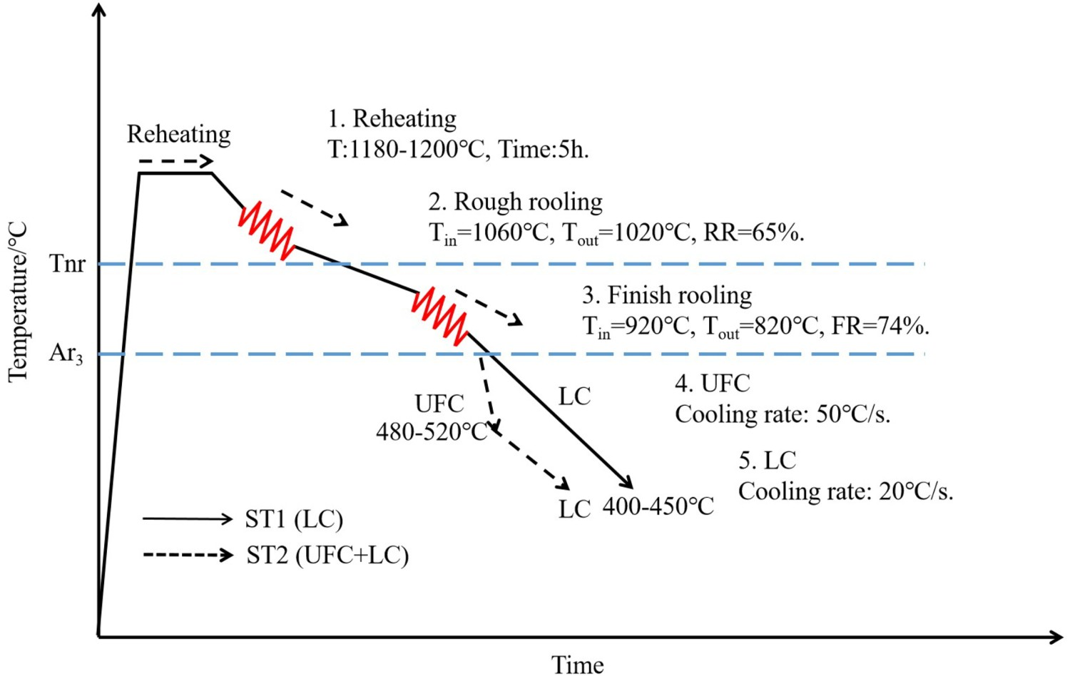
The ST1 and ST2 specimens used for microstructural observations and mechanical properties were taken from the quarter position of the rolled steel plates in the transverse direction. The dimension of tensile specimens is 12.7 mm in diameter and 50.8 mm in length. The full-sized V-notched Charpy impact and drop weight tear tests (DWTT) with a dimension of 305 × 76.2 × 27.5 mm3 were performed at −20°C and −15°C along the rolling direction (RD), respectively.
Microstructural characterization was performed by using optical microscopy (OM), field-emission scanning electron microscope (SEM, JEOL 7100F, Japan) equipped with an electron backscattered diffractometer (EBSD), and the transmission electron microscope (TEM, JEOL 2100F, Japan) for comparing the microstructural evolution of the two processes. The specimens for OM and SEM observations were mechanically polished and etched in a 4% nital solution. The specimens for EBSD observation were electropolished with 10%HClO4+90%ethanol solution to remove the deformation layer introduced during mechanical milling for observing the high-angle grain boundaries (HAG) evolution with a step size of 0.5 μm. The thin foils of 50mm thickness were prepared and then twin-jet electropolished using the solution of 8%perchloric acid and 92% ethanol at −20°C for observing the precipitate evolution. X-ray diffraction (XRD) was carried out on the specimens to analyse the dislocation density evolution, using a Rigaku Smartlab with Cu Ka radiation. The X-ray tube was operated at a voltage of 40 kV, a current of 40 mA and a speed of 2(°) min−1. The diffraction angle (2θ) range of all the measurements was recorded to 30–90°. The measurement of dislocation density was proposed by Williamson and Smallman [19,20]. The Crystallite sizes (D) were calculated from the full-width at half-maximum (FWHM) of the most intense line Bragg peak of the tested specimens. According to the formula after subtracting the widths due to instrumental broadening and strain effects, the lattice strain (ϵ) of the specimens was estimated from the XRD spectrum by using the following equation:
Results
Microstructure evolution with different cooling routes
Figure 2 shows OM and SEM in the ST1 and ST2 specimens at a mid-thickness with different cooling routes. It can be seen that the microstructure of the ST1 specimen was mainly dominated by quasi-polygonal ferrite (QF), together with granular bainite (GB) and a small amount of AF, as well as secondary martensitic/austenite (M/A) constituents. The microstructure was distributed in the ferrite matrix or along the ferrite boundaries, as shown in Figure 2(a,c). Compared with the ST1, the microstructure of the ST2 was refined and processed by UFC. The microstructure was predominantly composed of finer AF and GB. The ratio of AF, GB and M/A is higher than that of the ST1 specimen. Otherwise, some little QF and M/A were also observed in the microstructure (Figure 2(b,d)). It is widely accepted that AF nucleation occurred in the austenite grain interior and its morphology is fine lath. The number of AF increased with increasing cooling rate and rolling reduction [1]. However, the GB nucleation usually occurred at the deformed austenite grain boundaries and the shape is a block. The achievement of GB mainly controlled low rolling reduction and high cooling rate [21]. This result also implies that UFC can promote AF formation, which ensures microstructure homogeneity. The UFC provides a higher cooling rate and then increases the undercooling degree compared to conventional LC. The diffusion rate of carbon atoms decreased, and a higher ratio of dispersed M/A with a small size is obtained in the UFC process. OM and SEM micrographs of the specimens at a mid-thickness with different cooling routes. (a and c) LC and (b and d) UFC + LC.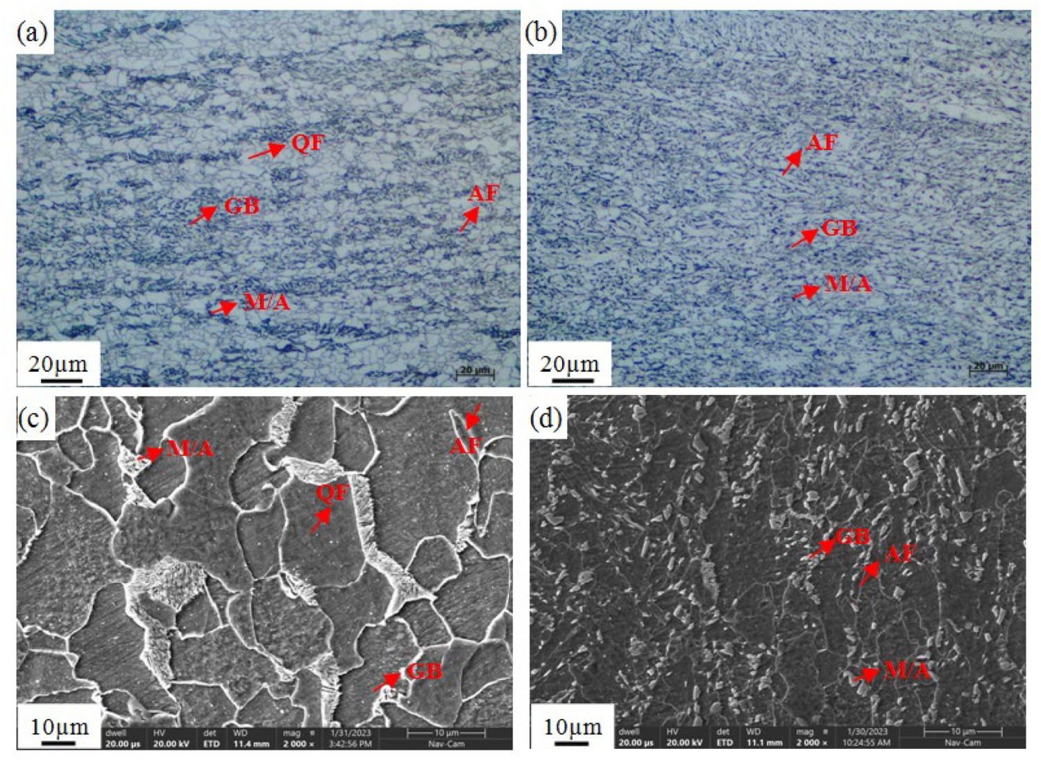
To obtain data on grain characteristics with different cooling routes, we performed EBSD tests on heart regions of X80 pipeline steels, as shown in Figure 3(a,b). Under the UFC condition, the effective average grain size of ST2 pipeline steels was 2.3 µm, whereas the effective average grain size of ST1 was 3.5 µm in the conventional LC technique. It demonstrates that UFC is characterized by a smaller effective grain size than LC. Moreover, the fraction of high-angle grain boundaries (HAG > 15°) obtained in UFC and LC processes was 45.2% and 46.7%, respectively, as shown in Figure 3(c). It represents that the specimens had similar ratios of HAG. Nevertheless, compared with the LC process, the average length of HAG for ST2 was higher compared to the LC process, as shown in Figure 3(d). This may be related to the characteristics of substructure in different cooling processes. With the increasing cooling rate, more substructure in AF was formed. The misorientation between acicular ferrite and substructure is classified as low angle [22]. Therefore, the total length of grain boundaries including high-angle and low-angle boundaries (LAG) is higher in UFC. It also causes the relevant fraction of HAG would decrease in the UFC process. In addition, the larger average length of HAG per area unit can block crack propagation. Based on the above analysis, it can be found that the smaller effective grain size and more HAG per unit area could contribute significantly to the toughness. Grain boundary maps and statistical data of the specimens at a mid-thickness with different cooling routes (LAGBs 2–15° and HAGBs >15° indicated by red and black lines) (a) ST1(LC), (b) ST2(UFC + LC), (c) Histogram of misorientation, (d) Grain shape.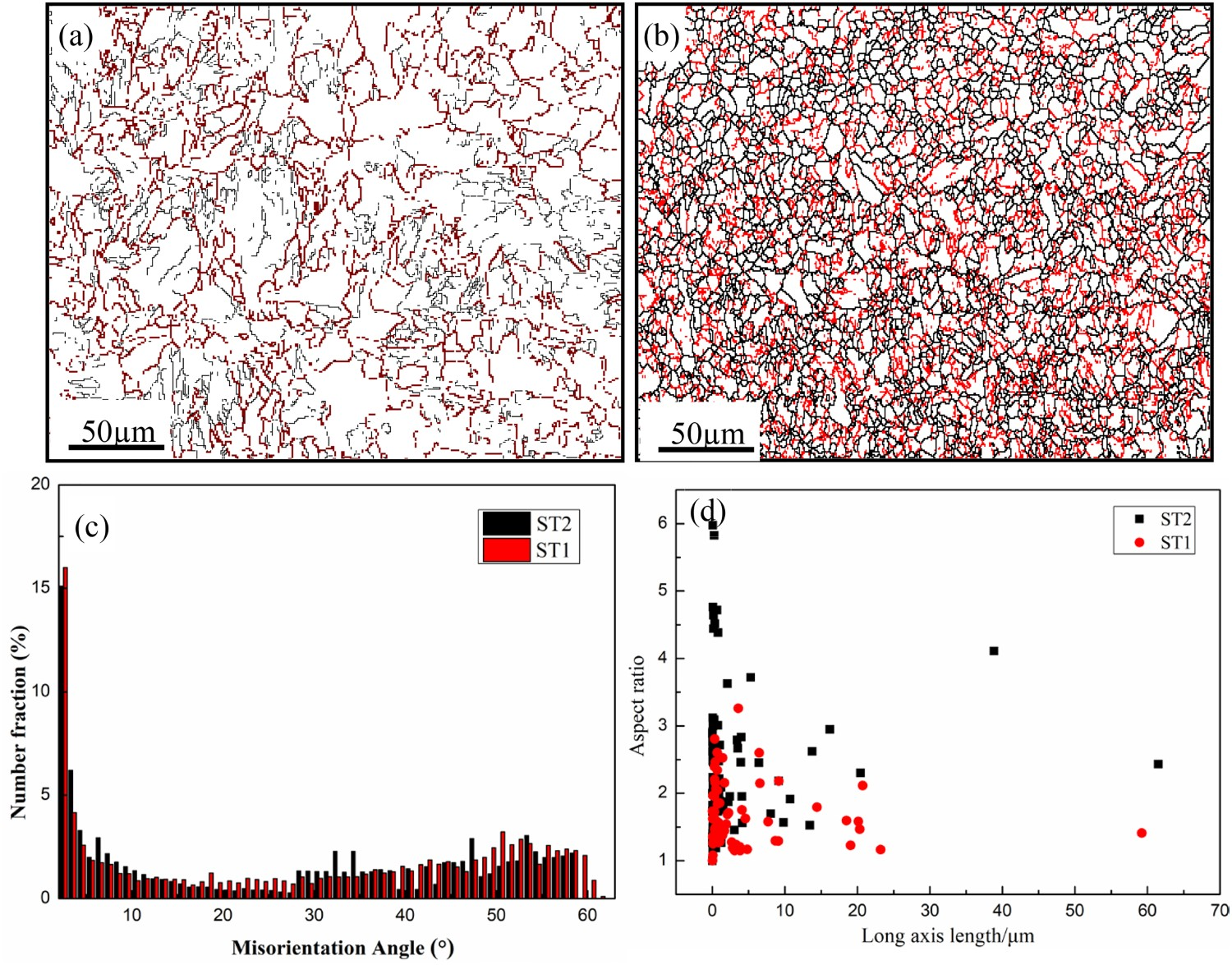
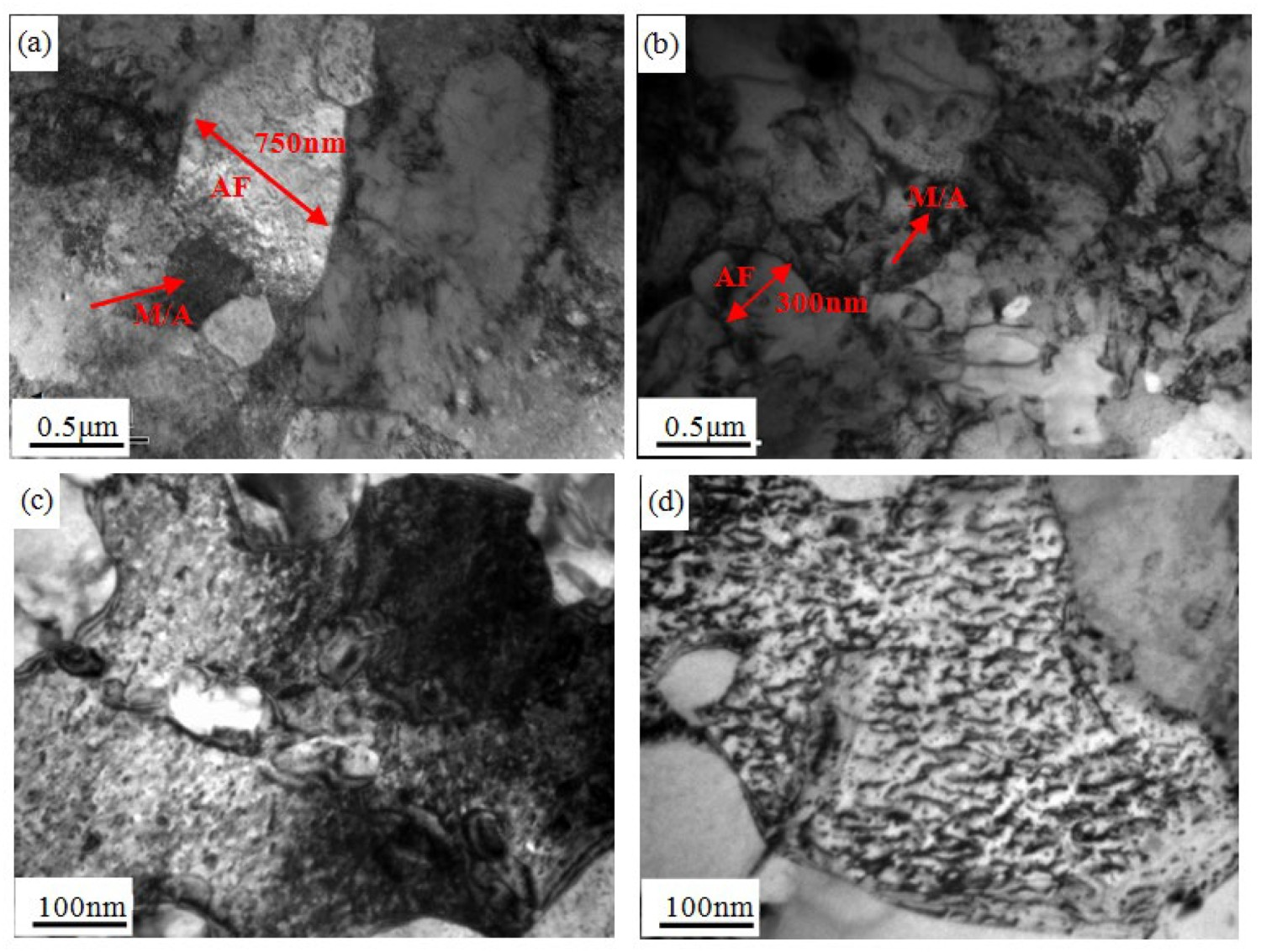
Figure 4 shows the XRD spectrum of the ST1 and ST2 specimens with different cooling routes. It is noted that the specimens are a single-phase body-centred cubic (bcc) structure. The crystallize size of the specimens is around 3.5 ± 0.15 μm and 2.9 ± 0.17 μm with the strain of 0.39% and 0.46% calculated by the Scherrer formula (see Equation 1) in the LC and UFC process, respectively. The precipitates are not found by XRD due to their low volume fraction and/or small size. Figure 5 shows the TEM images of the X80 pipeline steels with different cooling routes. It can be found that the fine AF was present in the X80 pipeline steel substructure in both processes. Moreover, the secondary M/A constituent was distributed at the junction of ferrite grains. The average width of AF in the ST2 specimen was 350 nm, which was smaller than the ST1 specimen (750 nm). In addition, a higher number density of dislocations was also found in the ST2 specimen of the ferrite matrix. The finer substructure can hinder dislocation slip during the hot deformation, which enhances the pipeline steel’s strength. XRD spectrum of the specimens with different cooling routes (a) ST1(LC), (b) ST2(UFC + LC). TEM micrographs of the specimens at a mid-thickness with different cooling routes (a and c) ST1(LC), (c and d) ST2(UFC + LC).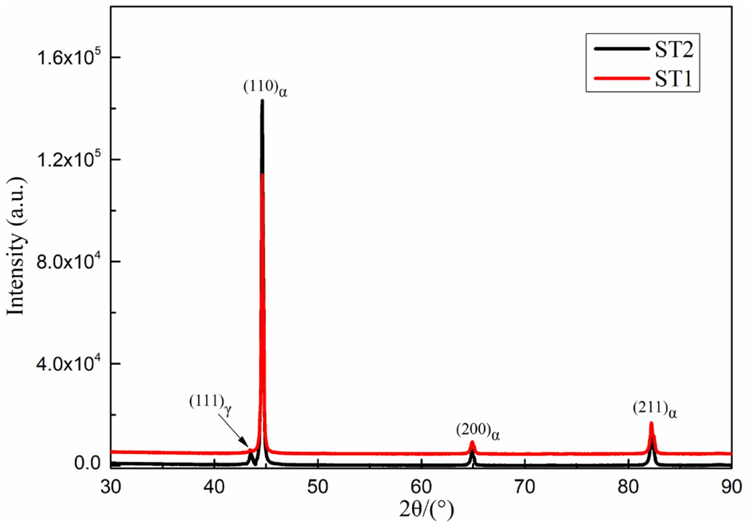
The morphologies of the precipitates formed at different cooling routes are shown in Figure 6(a,b). In the ST1 specimen, most of the precipitates were 20–60 nm. The distributions of precipitates of different sizes are summarized in Figure 6(c). The fraction of precipitates of size 20–60 nm and less than 20 nm were 68% and 32%, respectively. However, precipitates in the ST2 specimen were in the size range of 20–60 nm with a relative fraction of 99.6%. The precipitates with a size of less than 10 nm could hardly be found, and this may be related to the lower content of Nb and the higher cooling rate, which reduces the degree of precipitation. For the precipitates in ST1 and ST2 specimens, the average size, total number density and volume fraction are 14.3 nm, 6.1 × 10²¹ m3, 0.45% and 26.9 nm, 2.2 × 10²¹ m3, 0.19%, respectively. Morphologies of precipitates and size distribution at a mid-thickness with different cooling routes (a) ST1(LC), (b) ST2(UFC + LC), (c) Size distribution of precipitates.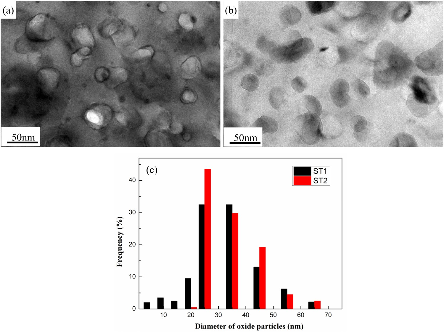
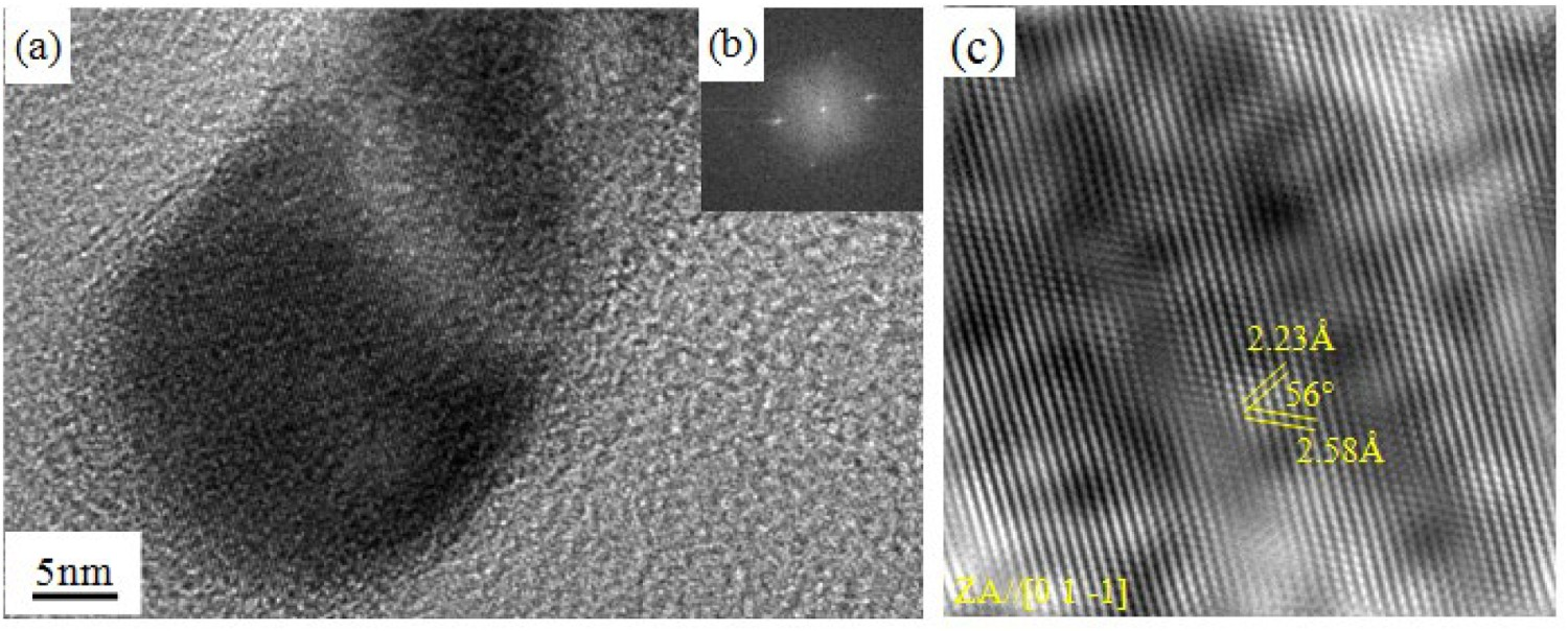
High-resolution transmission electron microscope (HRTEM) imaging was performed to identify the crystal structure of these precipitates in the ST1 specimen. According to the statistical results of HRTEM analyses, the structure of these large precipitates (>20 nm) is shown in Figure 7. The two measured atomic plane distances are 2.12 Å and 2.44 Å with an angle of 54°, respectively. The lattice structure of this large precipitate (diameter, 28 nm) from the image is in good agreement with the cubic structure TiN with a zone axis of [0 1 −1]. Figure 8 shows an HRTEM lattice image of these small precipitates (<20 nm), its fast Fourier transform (FFT) image and FFT filtered image with an incident electron parallel to the [0 1 −1] zone axis. Two measured atomic plane distances are 2.58 Å and 2.23 Å with an angle of 56°. This result is in good agreement with the cubic structure NbC. Based on the HRTEM results, it can be inferred that the solubility of Nb and Ti in the austenite temperature region decreased in the finish rolling stage at 820°C. Under this condition, strain-induced precipitation of precipitates occurred. Some groups have also found that the composition of precipitates was Ti-rich nitrides and Nb-rich carbides. Ti-rich nitrides were larger than Nb-rich carbides [22]. Solute concentrations of Ti-rich nitrides and Nb-rich carbides were calculated from the amount of solute Nb and Ti previously characterized. According to the assumption, the dissolution of Ti-rich nitrides and Nb-rich carbides released on average the amount of Ti, C and N in proportion to the amount of Nb inside the precipitates. According to the solubility equations, the mass fractions xi
,ppt of the elements i = Nb, Ti, C, N, and Nb in the alloys are 0.071–0.076, 0.012–0.013, 0.045–0.047, and 0.0049–0.0051, respectively (wt-%) at the heating temperature of 1180–1200°C. According to the calculation and experimental results, the TiN precipitates first, then NbC during the rolling and cooling processes. According to the TEM results, the volume fraction of the precipitates is 0.45% and 0.19% in ST1 and ST2 specimens, respectively. It also found that the thermal stability of NbC is higher than TiN, which can reduce the NbC precipitate growth [23–26]. The contribution degree of precipitate strengthening obtained is highly dependent upon the alloy system involved, the volume fraction and size of the precipitates, and the nature of the interaction of the precipitates with dislocations. TEM analysis of TiN precipitates in the ST1 specimen (a) Bright field, (b) FFT diagram of the micrographs in (a), (c) FFT filtered images derived from the images (a). TEM analysis of NbC precipitates in the ST1 specimen (a) Bright field, (b) FFT diagram of the micrographs in (a), (c) FFT filtered images derived from the images (a).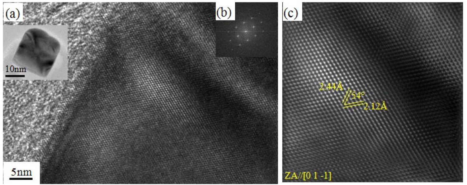
Mechanical properties
Comparison of mechanical properties obtained with different cooling rates of X80 pipeline steels.
Discussion
Effect of controlled cooling routes on microstructure and toughening mechanism
The low-temperature toughness of high-strength pipeline steel is related to the material’s microstructure and composition. The typical microstructure includes AF/QF/GB and M/A, and the pipeline steel with mainly AF and GB has an excellent low-temperature toughness. It is found that the composition could affect the microstructure and mechanical properties. If a suitable TMCP technique can compensate for the loss in strength and toughness by reducing Nb and Mo contents, the low-cast alloy composition can be applied. A higher cooling rate provides a driving force for controlling the microstructure or phase transformation during the cooling process in improving the strength and toughness of low-cost pipeline steel. It was found that the mechanical properties of low-alloy pipeline steels were improved by using the UFC technique through the control of microstructure. In this aspect, Nb and Mo reduced with new cooling routes of UFC combined with LC is an ideal technique in controlling the production cost.
The influence of UFC combined with LC on the optimization of composition design is discussed in terms of strengthening mechanisms of Nb and Mo in high-grade pipeline steel. Mo improves hardenability. However, the reduction of Mo contents seriously influences the AF or GB transformation at the same cooling rate [24]. Moreover, the influence of reducing Nb content on loss in strength has also to be taken into consideration. The dynamic recrystallization of austenite and precipitation of NbC is delayed by Nb addition. Based on the above analysis, the increase in cooling rates and reduction of Nb and Mo can affect the average grain size and the number density and size of precipitates. The influence of reducing Nb contents on NbC precipitates is shown in Figure 6. It is found that the number density of precipitates with a size below 20 nm was less in the ST2 specimen than ST1 specimen. The size of precipitates less than 20 nm is effective for precipitation strengthening. Therefore, the contribution of precipitation strengthening in the UFC pipeline steel is less than the LC technique. As compensation, the UFC steel owned finer grain size than the LC steel due to the higher cooling rates. It led to the grain size strengthening in UFC steel being more important than the LC process. It is accepted that the pancaked austenites are obtained after two stages of rolling during the TMCP process. The formation of dislocations and deformed bands provide driving force for the subsequent phase transformation process. In the next cooling process, the LC with a lower cooling rate (20°C s−1) was adopted for the ST1 specimen, while the ST2 with a higher cooling rate (50°C s−1) was used for the UFC process. Large amounts of undercooling degree and more crystal defects provided greater driving force and nucleation sites for AF and GB along austenite intragranular or grain boundaries, respectively. Hence, the grains of UFC steel were finer than the grains obtained by the LC process. The decreased average grain size impedes the crack’s propagation and improves the low-temperature toughness.
Based on the above analysis, it is obvious that the contribution of grain strengthening in the UFC process was more than in the LC process. However, the precipitation strengthening in the LC process was more. The loss in strength due to the reduction in Nb and Mo can be compensated by the application of the UFC technique through the refinement of the grains. The strength mechanism contributions in UFC and LC are discussed below carefully.
Strengthening mechanisms of X80 pipeline steels at different cooling routes
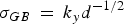
The measured mechanical properties of the experimental steels with different cooling routes are shown in Table 2. The results showed that the mechanical properties satisfy the API SPEC 5L-X80 standards. The different strength mechanisms in UFC and LC steels were presented under different cooling routes. The strength contributions were calculated based on the microstructural data. The difference in the strength during processes UFC and LC for micro-alloyed pipeline steels can be explained as a combination of matrix strength and contributions from a variety of strengthening mechanisms as follows: (1) solid solution strengthening (σss ), (2) grain refinement (Hall-Petch relationship, σGB ), (3) dislocation strengthening (σDis ) and (4) dispersion strengthening from precipitates (σp ) [27–29].
The base strength σi-m
comprises contributions from matrix strength and grain boundary strengthening contribution.


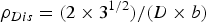
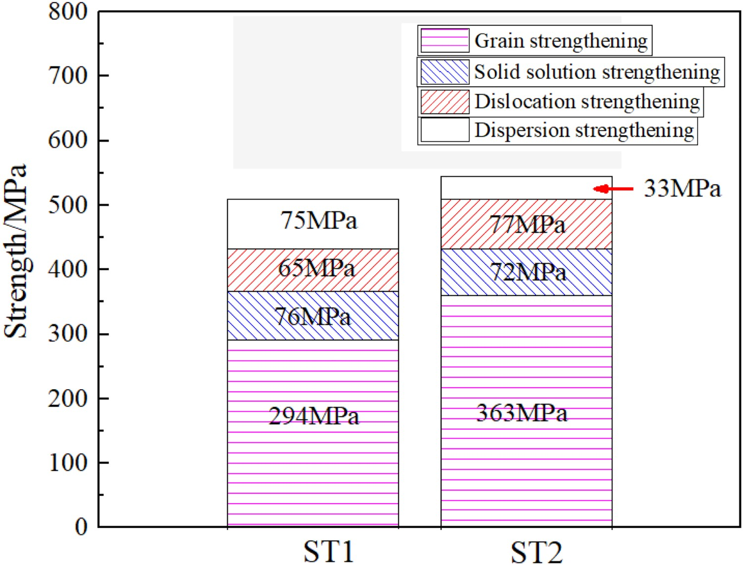
Dislocation strengthening (σdis
) plays an important role in the improvement of strength. This contribution is given by [31]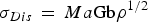
The contribution of dispersion precipitation strengthening was calculated by using the classical Ashby–Orowan equation [27] Histogram of strength contributions induced by different strengthening mechanisms.
In addition, the change in Nb and Mo content needs to be considered by dispersion strengthening mechanisms. Figure 9 shows that the LC steel had a lower strength increment from grain size strengthening and a higher strength strengthening contribution from precipitation strengthening compared with the UFC steel. It also further confirmed that the loss in strength caused by the reduction in microalloying elements in UFC can be compensated by enhancing the cooling rates during the controlled cooling process.
Conclusions
This research addresses the effect of the TMCP technique with different cooling rates on the microstructure and mechanical properties of the X80 pipeline steels. The results can be summarized as follows: The microstructure was mainly dominated by quasi-polygonal ferrite (QF), together with granular bainite (GB) and a small amount of AF, as well as secondary martensitic/austenite (M/A) constituents processed by LC. However, the grains were refined and processed by UFC. The microstructure was predominantly composed of finer AF and GB. The ratio of AF, GB, and M/A is higher than that of the LC process. The fraction of high-angle grain boundaries (HAG > 15°) obtained in UFC and LC processes was similar at 45.2 and 46.7%, respectively. The average length of HAG for UFC was higher compared to that of the LC process. With the increasing cooling rate, more substructure in AF was formed. The large fraction of AF and small grain size of UFC steel ensured a high qualification rate of DWTT properties and good toughness with low alloy composition. The mechanical properties of UFC and CP steels met the specification of API SPEC 5L-X80 standards. The main strength mechanisms in LC steel were grain strengthening, dislocation strengthening, and precipitation strengthening. However, grain strengthening and dislocation strengthening were the dominant strengthening mechanisms in the UFC process. The supply for strength loss by reducing Nb and Mo contents in UFC steel was compensated by enhancing the effect of grain strengthening in the TMCP process.