
Abstract
In this study, a permanent magnet stirrer was constructed for the implementation of experiments on different magnetic field stirring modes. Through experiments, it can be observed that when the fixed speed of 200 rpm and the alternate stirring mode of magnetic field was adopted, the loose area in the core of ingots was reduced from about 72 mm2 to 21 mm2, which significantly improved the density and element uniformity of the ingot. A Φ220 mm SAE1527 round billet was selected as industrial trial steel. When the stirring current and frequency was 350 A and 3 HZ, the electromagnetic stirring of the mold was adjusted from continuous stirring to alternate stirring mode. The solidification structure of the billet has been improved to a certain extent. Furthermore, the number of spot segregation larger than 0.5mm2 was reduced from 43 to 26, thereby improving the uniformity of internal elements in the billet.
Introduction
With the increasing use of steel pipe year by year, the requirements of quality for steel pipe were becoming increasingly stringent, otherwise, there will be serious consequences [1,2]. For example, the failure of the axle pipe used for vehicle transportation will cause serious traffic accidents and endanger the safety of life and property. Most of the reasons for the failure of the pipe come from the internal quality of the product, such as the banded structure and uneven distribution of elements [3–6]. These defects were mainly inherited from the spot segregation inside the continuous casting billet, so optimizing the internal quality of the billet is one of the effective ways to fundamentally solve the internal defects of the pipe [7–9].
Due to the special cross-sectional morphology of the round billet and strict requirements for ovality during rolling process, the soft reduction was rarely used in the continuous casting process. Instead, the quality was mainly improved by controlling the superheat of molten steel in tundish and combining with the electromagnetic stirring process. The electromagnetic stirring process mainly drives the molten steel in the mould through electromagnetic force to improve the flow field of molten steel, thereby reducing the superheat of high-temperature molten steel and redistributing the accumulated solute at the solidification front [10–13]. Most scholars have shown that in order for the electromagnetic stirring process to improvement the internal quality of the casting billet, it is necessary to match appropriate stirring parameters, otherwise, it will deteriorate the quality of the billet [14–18]. Therefore, it is particularly important to determine the reasonable electromagnetic stirring parameters in the continuous casting process.
At present, in the process of round billet, the mould electromagnetic stirring mainly adopted the continuous stirring mode in a single direction [19,20]. In order to investigate the effect of mould alternate stirring mode on the internal quality of round billet, a pair of NdFeB permanent magnets was selected as the magnetic field source and a permanent magnetic stirrer was constructed. Alternate stirring experiments were performed using a mass ratio of 80%-20% Sn-Pb alloy and the internal solidification structure of ingots were compared. The magnetic and flow field coupling model of mould was established. According to the results of molten steel flow rate and liquid level fluctuation, the reasonable parameters of mould alternate stirring were determined, and the industrial test was carried out. By detecting and comparing the solidification structure and spot segregation of continuous casting round billet before and after the test, the improvement effect of alternate stirring mode on the internal quality of round billet was quantitatively evaluated, which provided a new direction for the internal quality improvement of continuous casting round billet.
Experiment section
Construction of the PMS
In industry, electromagnetic stirrer was mainly used to stir molten steel. The equipment mainly generates a magnetic field by inputting alternating current into the iron core, which in turn acts on the molten steel. In order to simplify the experimental equipment, a high magnetic permanent magnet was selected as the magnetic field source and a permanent magnet stirrer (PMS) was built. The schematic diagram is shown in Figure 1. In this study, the magnetic field was generated by a pair of N38H series NdFeB permanent magnets, with a residual magnetization Br of about 1.23 T and a maximum operating temperature of 120°C. The N and S were installed opposite to each other to ensure the generation of a completed magnetic field. The permanent magnet was driven by the motor to rotate the magnetic field, and the speed can be adjusted in the range of 0–300 rpm. The Sn-Pb alloy with low melting temperature was used to replace the high-temperature molten steel, and the primary physical parameters are shown in the relevant literature [21]. The schematic diagram of the PMS. ① rotating electrical motor; ② permanent magnets; ③ fire-resistant cotton; ④ crucible; ⑤ the equipment frame; ⑥ rotating bearing.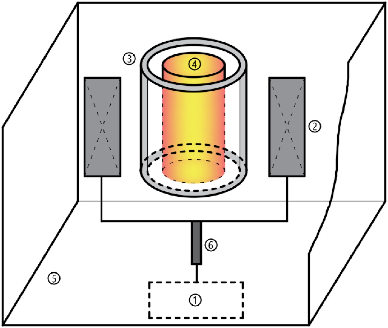
The equipment frame was constructed of aluminium alloy to stabilize the experimental equipment. The upper part was welded with a copper groove of suitable size, while the insulation cotton was embedded, which can stabilize the crucible during experiment. On the other hand, it can prevent excessive diffusion of high temperature outward, thereby reducing the magnetism of the permanent magnet.
Simulation of magnetic field distribution in the PMS
To systematically study the magnetic field distribution inside the crucible of the PMS, Maxwell software was used to perform geometric modelling based on the equipment size. The basic size parameters of the PMS are shown in Table 1, and the morphology of the model after meshing is shown in Figure 2. Mesh division diagram of 3D model of the PMS. The basic size parameters of the PMS.
Different stirring speeds corresponding to the simulation calculation.
The magnetic intensity and Lorentz force distribution in the crucible under different stirring speeds were calculated by the model, which lays a theoretical foundation for the subsequent experiments. Figures 3 and 4 shows the distribution of magnetic intensity and Lorentz force at the centre cross-section of the crucible at different stirring speeds. The units of magnetic intensity and Lorentz force are mT and N. The cloud diagram of magnetic intensity of crucible centre cross-section under different stirring speeds. (a) 100 rpm, (b) 200 rpm, (c) 300 rpm. The cloud diagram of Lorentz force of crucible centre cross-section under different stirring speeds. (a) 100 rpm, (b) 200 rpm, (c) 300 rpm.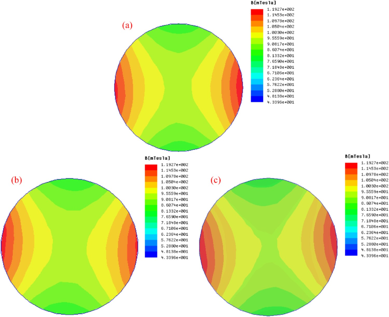
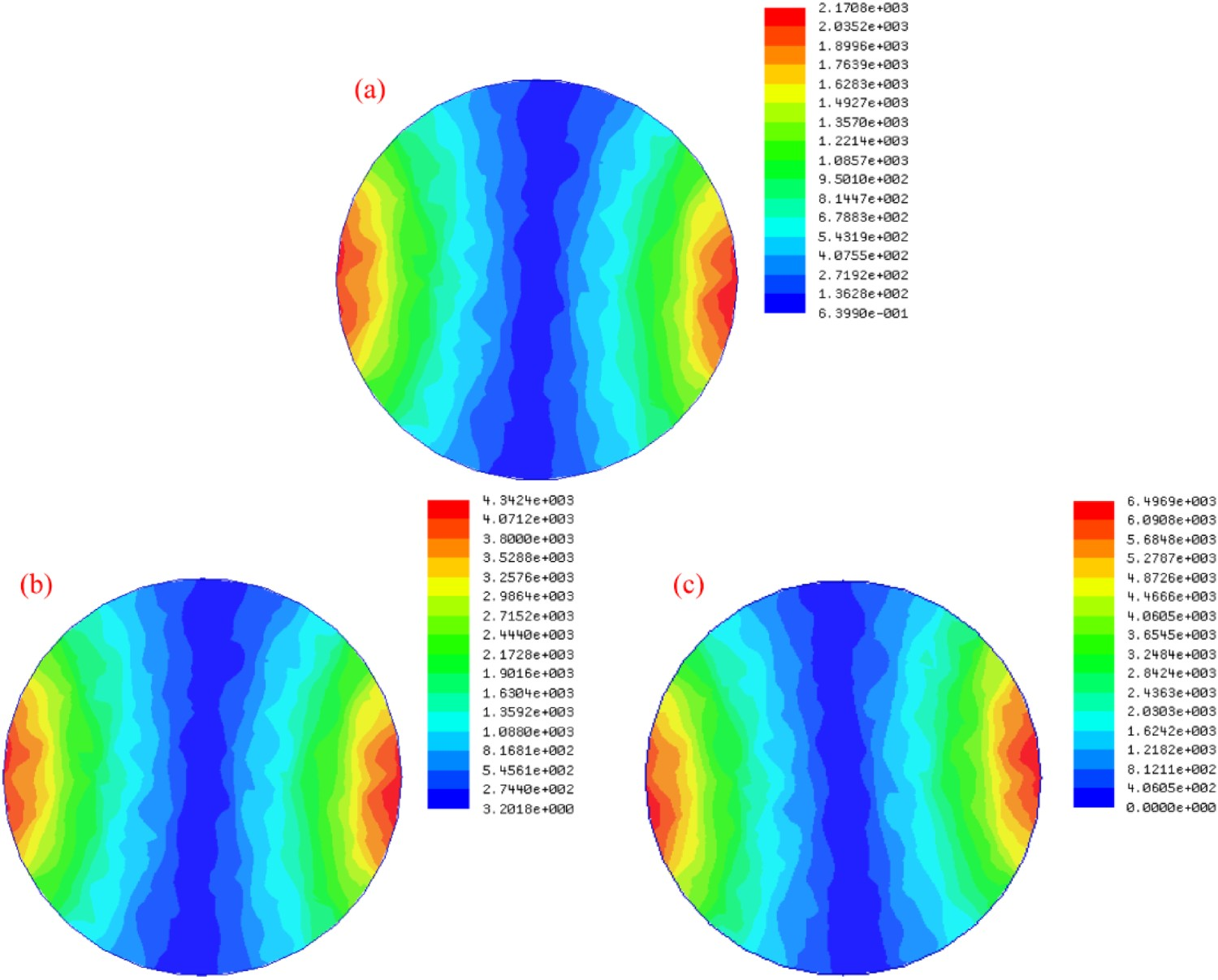
Figure 5 shows the distribution curves of the magnetic intensity and Lorentz force inside the crucible at the centre of the permanent magnet under different stirring speeds. Due to the symmetry of the measurement results, the measurement results on one side were selected for explanation. From the data in Figure 5, it can be seen that the magnetic intensity and Lorentz force inside the crucible exhibit a distribution pattern of ‘small in the middle and large at the edge’. When the magnetic field speed was 100, 200, and 300 rpm, the magnetic intensity at each position in the crucible was basically the same. The magnetic intensity at the centre and edge of the crucible was 954GS and 1191GS, respectively. It shows that the magnetic field has little effect on the distribution of magnetic intensity in the crucible at different stirring speeds, and changing the rotating speed of the permanent magnet will not affect the magnetic intensity at different positions in the crucible. On the contrary, for the distribution of Lorentz force, when the magnetic field speed was 100, 200 and 300 rpm respectively, the Lorentz force at the centre of the crucible was zero, and the maximum Lorentz force at the edge of the crucible was 2170, 4342 and 6497 N·m−3 respectively. It shows that with the increase of magnetic field stirring speed, the Lorentz force acting on the molten alloy in the crucible gradually increases. The distribution curves of magnetic intensity and Lorentz force in the centre cross-section of crucible at different stirring speeds. (a) Schematic diagram of measurement points; (b) magnetic intensity; (c) Lorentz force.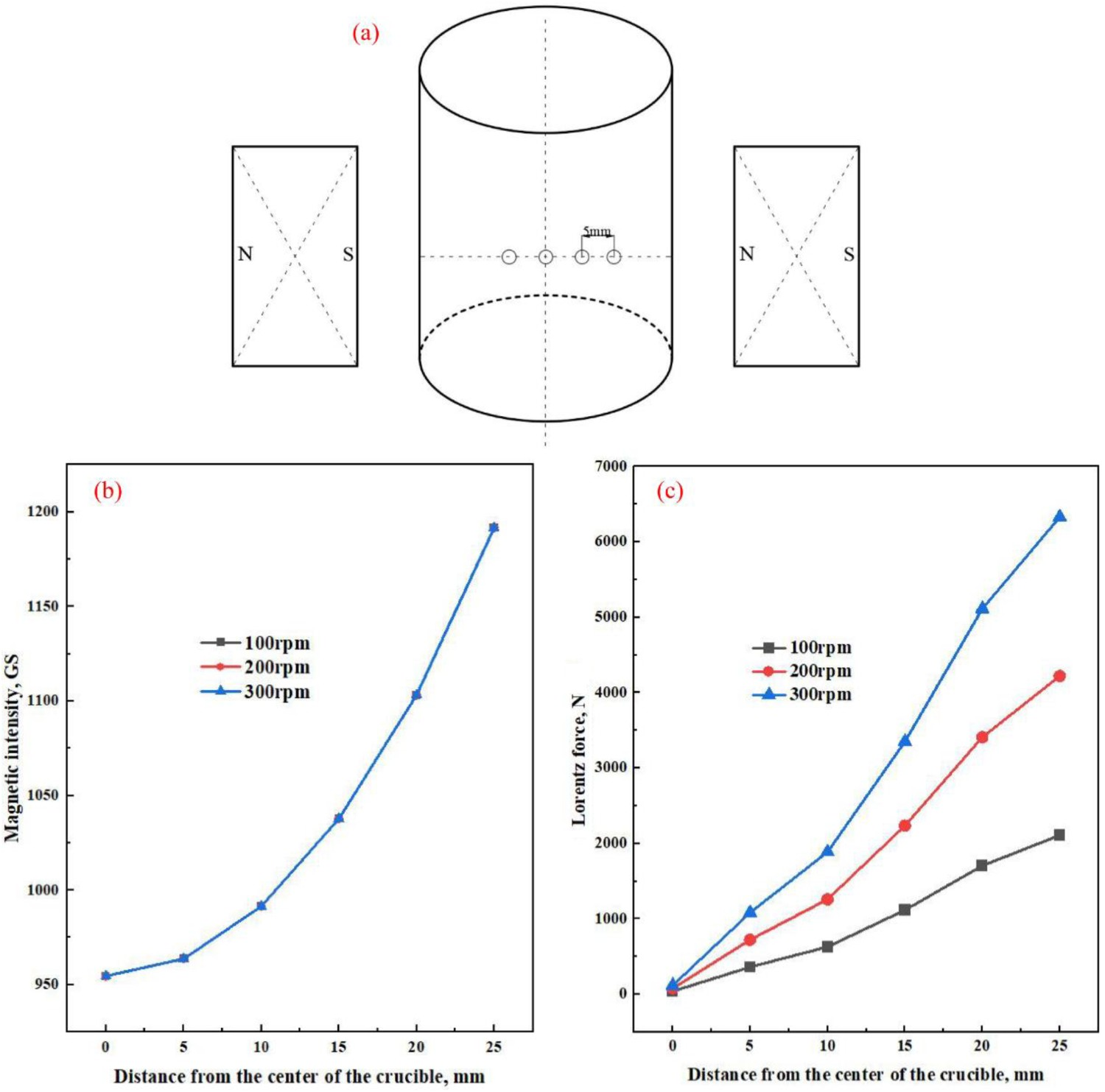
Preparation of experiments
According to the simulation calculation results, the faster the speed of the magnetic field in the permanent magnet stirrer, the greater the Lorentz force it exerts on the molten alloy, resulting in higher stirring efficiency. However, the setting of the speed needs to consider the bearing capacity of the rotating motor, and at the same time, excessive stirring speed of the high-temperature alloy in the crucible can easily cause splashing, causing certain safety hazards.
Test scheme of permanent magnetic stirring.
PMS-CS: continuous stirring; PMS-AS: alternate stirring.
Industrial trials
Establishment of geometric model
Chemical composition of test steel SAE1527, %.
The main size parameters of the mould electromagnetic stirrer.
The main size parameters of the billet model.
According to the above size parameters, the 3D model of mould electromagnetic stirrer and round billet was established by using Solidworks software, as shown in Figure 6. The 3D model of mould electromagnetic stirrer and round billet. (a) Mould electromagnetic stirrer; (b) round billet.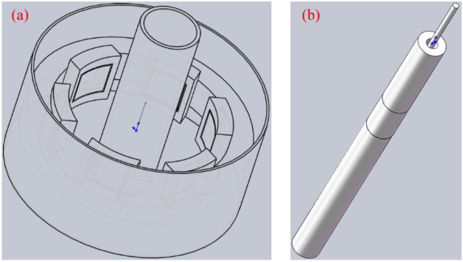
The equations involved in solving the electromagnetic field and flow field will not be repeated here. The basic assumptions for establishing the mould magnetic field and flow field model can be found in relevant literature [23–25]. Ansys software was used to bring the calculated magnetic field results into the flow field model for coupling, so as to obtain the calculation results of the flow field in the mould under different electromagnetic stirring parameters.
Formation of parameters for mould electromagnetic alternate stirring
During the continuous casting process, the stirring current and frequency of the Φ220 mm SAE1527 were 350 A and 3 HZ respectively. To determine the appropriate parameters for alternate electromagnetic stirring, the magnetic field flow coupling models were used to calculate the flow field on the cross-section of the mould centre and the fluctuation of molten steel level in the mould. The appropriate alternate electromagnetic stirring parameters were determined by comparing the flow field of molten steel and the fluctuation height of molten steel level at the end of positive and negative clockwise stirring time. In this study, the simulation results of the positive and negative clockwise stirring time ‘7s-3s-7s’ with the electromagnetic stirring current and frequency of 350 A and 3 HZ were taken as examples.
Figures 7 and 8 are the flow field of molten steel in the centre cross-section of the mould and the fluctuation of molten steel level in the mould under the alternate stirring mode. The units of speed and fluctuation of molten steel are m s-1 and mm, respectively. The velocity of molten steel in the centre cross-section of the mould. (a) positive clockwise stirring time 7 s; (b) standing time 3 s; (c) negative clockwise stirring time 7 s. The fluctuation of molten steel in the mould. (a) positive clockwise stirring time 7 s; (b) standing time 3 s; (c) negative clockwise stirring time 7 s.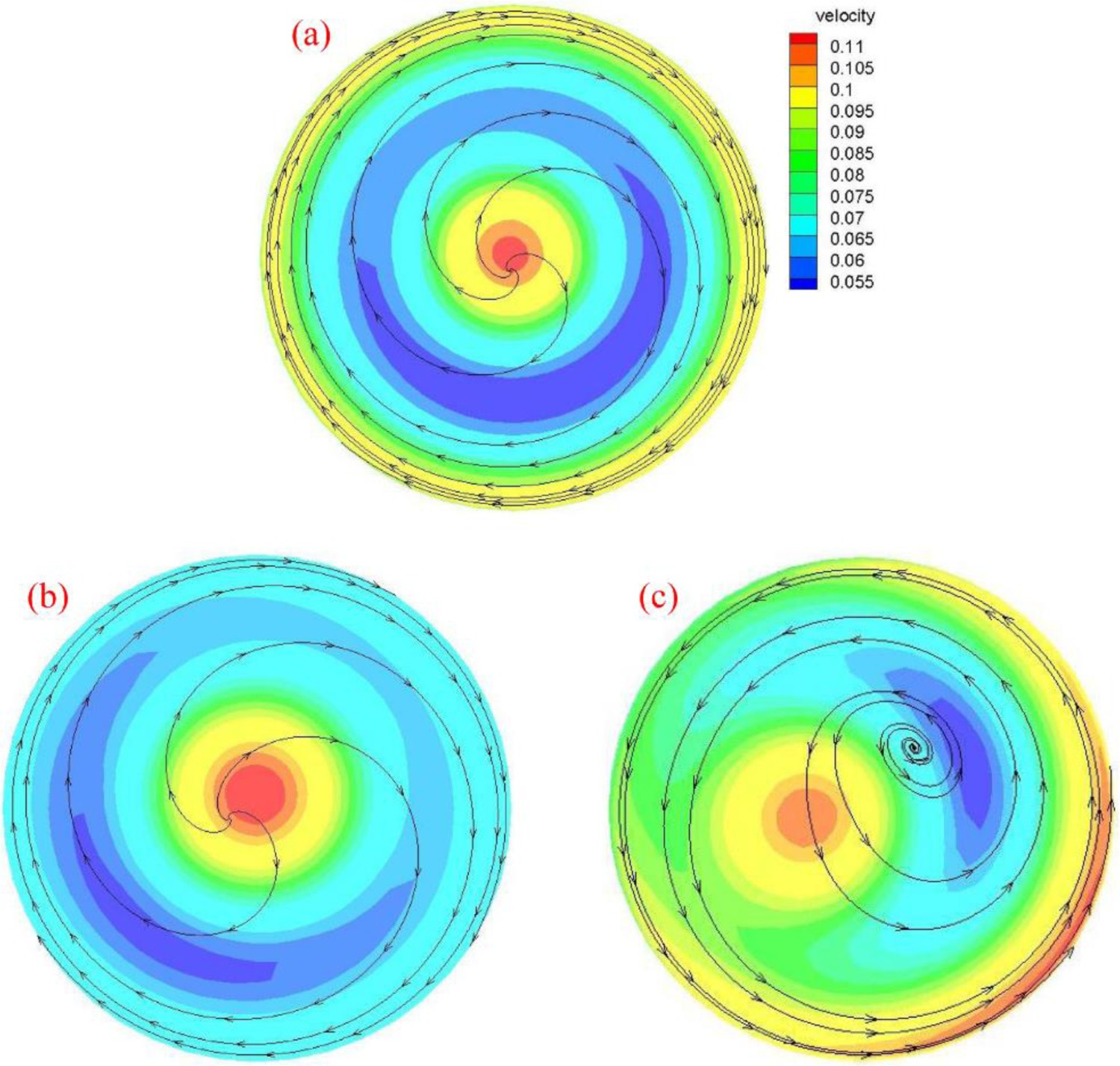
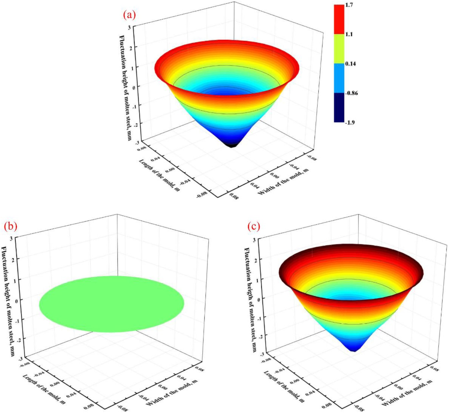
From the comparison of Figures 7 and 8, it can be seen that the flow field of molten steel in the centre cross-section of the mould stirrer was basically symmetrically distributed throughout the alternate stirring cycle, and the flow field state was good. After positive and negative clockwise stirring for 7 s, the rotation speed at the edge of the mould was 0.1 m·s−1, but the rotation direction of the molten steel was opposite. After the electromagnetic field stop stirring for 3 s, the rotational speed at the edge of the mould was about 0.05 m·s−1. The fluctuation morphology of the molten steel level in the mould at different stirring time was analysed. When the molten steel was stirred by the magnetic field, the molten steel level in the mould exhibits a morphology of low centre and high edge. When the positive stirring time for 7 s, the fluctuation range of the molten steel level in the mould was −1.80 mm∼1.70 mm; after the electromagnetic field stops stirring for 3 s, the molten steel level in the mould tends to stabilize, with a height range of −0.026∼0.030 mm, approaching zero; and then after 7 s of negative clockwise stirring time, the fluctuation range of the molten steel level in the mould was −2.22 mm∼1.30 mm. Throughout the entire alternate stirring cycle, the height range of the molten steel level in the mould does not exceed ±3 mm, within a reasonable range of molten steel level fluctuation.
Therefore, in the industrial test of this study, the mould electromagnetic stirring current and frequency were 350 A and 3 HZ respectively. The electromagnetic stirring mode was divided into two types: continuous stirring in one direction, and alternate stirring in the positive and negative directions. The stirring time in the positive and negative directions was 7 s, and the middle pauses for 3 s. The rotation direction of the electromagnetic field was controlled by the electromagnetic stirring program.
Results and discussion
Detection of solidification structure
In order to clarify the influence of different magnetic field stirring modes on the solidification structure of Sn-Pb alloy ingots, the longitudinal section of the ingot was selected for observation. The ingot was cut from the longitudinal central section. After the longitudinal samples were polished, the polished surface was etched using acid solution (2 ml of HCL, 10 g of FeCl3 and 100 ml of H2O) [26]. The macroscopic morphology of the longitudinal section of the specimens was photographed using Canon D60, and the microscopic morphology of the sample was observed using a DM4M optical microscope. The schematic diagram of sample processing and testing is shown in Figure 9. Schematic diagram of sample processing and testing.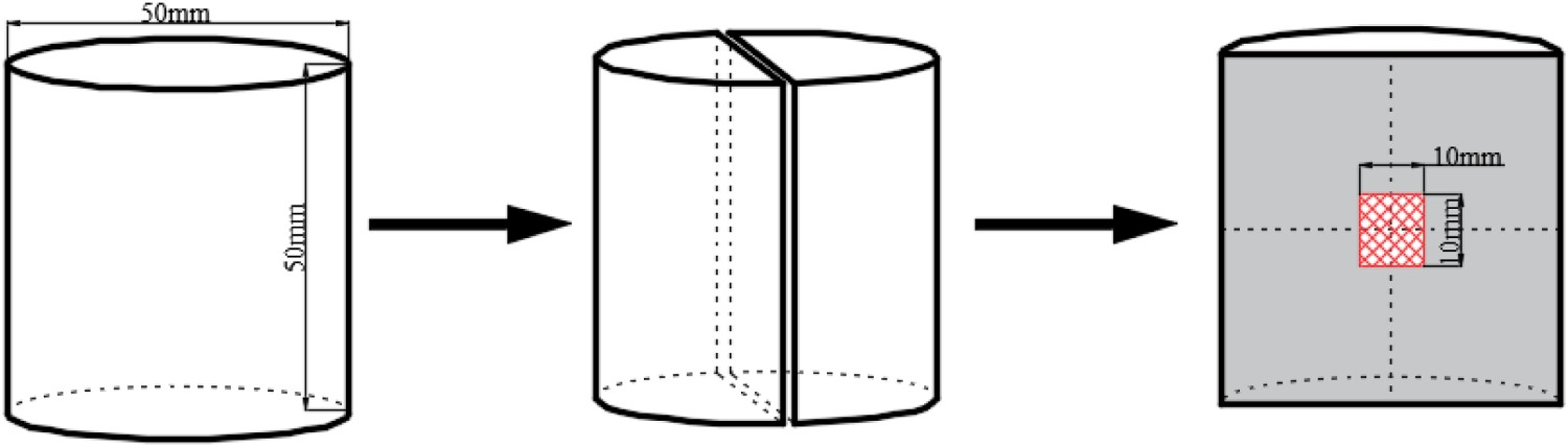
There are differences in section shape and composition between continuous casting billet and Sn-Pb alloy ingot, so there are difference between in sample processing and solidification structure erosion. A sample with thickness of 20 mm along the casting direction was taken. The sample of cast bloom was etched about 60 min under the temperature 70–90°C with the following solution: HCl (100 cm3) + water (100 cm3), and then the dendrite morphology of solidification structure was photographed by Canon D60. The proportion of solidification structure on the cross-section of round billet under different electromagnetic stirring modes was counted. At the same time, the morphology and quantity of spot segregation in the range of 100 mm diameter of the core of the round billet were observed and counted, and the influence of different electromagnetic stirring modes on the internal quality of the round billet was quantitatively evaluated. The schematic diagram of round billet processing and detection position is shown in Figure 10. The schematic diagram of round billet processing and detection position.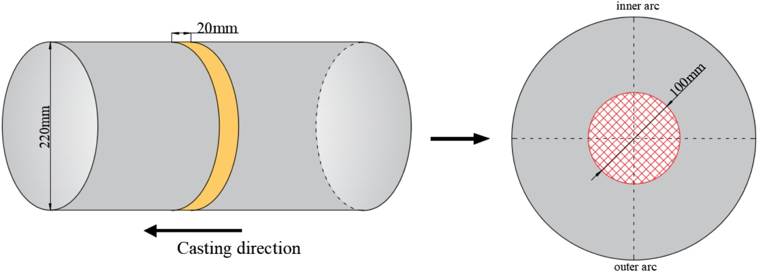
Solidification structure of Sn-Pb alloy ingots
The rotating magnetic field drives the molten alloy in the crucible to move, thereby affecting the solidification structure of the ingot. This article mainly studies the effects of different magnetic field speeds and stirring modes on the solidification process of alloy ingots. The macroscopic solidification structure of the longitudinal section of Sn-Pb alloy ingots under different magnetic field stirring modes is shown in Figure 11. The solidification structure of longitudinal section of ingots under different magnetic field stirring modes. (a) continuous stirring, 100 rpm; (b) continuous stirring, 200 rpm; (c) alternate stirring, 200 rpm.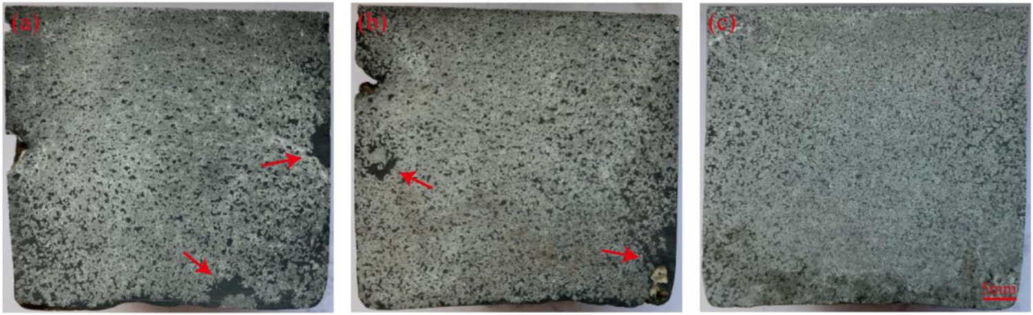
It can be seen from Figure 11 that when the magnetic field adopted the continuous casting mode, there were obvious cracks at the edge of the longitudinal section of the ingot. When the stirring speed was 100 rpm, the bottom of the ingot has a tendency to shrink towards the core of the ingot, and the shrinkage size was about 3 mm. As the stirring speed increases to 200 rpm, the shrinkage at the bottom of the ingot disappears. Furthermore, when the magnetic field adopted the continuous casting mode and the stirring speed was increased from 100 rpm to 200 rpm, the deposition trend of Pb element at the bottom of the ingot was reduced, but some Pb element were still found at the corner of the ingot and the edge of the longitudinal section (as shown in the red arrow in the Figure 11). When the stirring speed was 200 rpm and the magnetic field adopted the alternate stirring mode, the Pb element group in the ingot is almost completely dispersed, and the element distribution uniformity is the best. Figure 12 is the schematic diagram of the microstructure of the ingot centre under different magnetic field stirring modes. The dark grey area in the figure is considered to be a loose area (as shown the red wireframe area in the Figure 12). After the Pb element in the sample was eroded, it appears dark grey under the optical microscope, which is just in contrast to the bright white grains. The area of loose area in the figure was counted by Image-Pro plus 6.0 software. Under the continuous casting mode of magnetic field, when the stirring speed was 100 rpm, there was obvious loose morphology in the centre of the ingot, and the loose area was about 125 mm2. When the stirring speed was increased to 200 rpm, the loose area in the centre of the ingot shows a decreasing trend, but it is not completely eliminated, and the loose area was about 72 mm2. When the magnetic field adopted alternate stirring mode and the speed was 200 rpm, the loose area in the centre of the ingot was further reduced to about 21 mm2, and the density of the core structure of the ingot was significantly improved. The schematic diagram of the microstructure of the ingot centre under different magnetic field stirring modes. (a) continuous stirring, 100 rpm; (b) continuous stirring, 200 rpm; (c) alternate stirring, 200 rpm.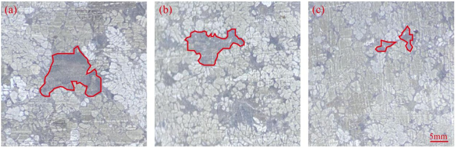
Through the above detection, it can be concluded that under the same stirring speed, the alternate stirring mode of magnetic field was more conducive to the improvement of solidification structure and element segregation in the core of ingots. The reason is that when the magnetic field adopted the continuous stirring mode, the rotation speed of the molten alloy in the crucible increases continuously and then tends to be stable. Since the Pb element was easy to accumulate between the dendrites [27], the unsolidified alloy inside the crucible has a higher cutting efficiency for the accumulated Pb clusters during the process of gradually increasing the rotation speed of the molten alloy in the crucible, which can reduce the size of the Pb clusters to a certain extent. With the continuous increase of magnetic field rotation time, the speed of molten alloy in the crucible tends to stabilize, and its flow rate direction was consistent with the growth direction of Pb element clusters, which will greatly reduce its cutting efficiency on Pb element clusters. In contrast, the magnetic field alternate stirring mode, due to the repeated changes of the magnetic field in a motion cycle, the molten alloy in the crucible has been in an unstable flow state of clockwise and counter clockwise, and the molten alloy will always maintain a large relative velocity of the Pb element cluster, thus greatly improving the cutting efficiency between each other. Figure 13 is the schematic diagram of the influence mechanism of different magnetic field stirring modes on the solidification structure of ingots. The schematic diagram of the influence mechanism of different magnetic field stirring modes on the solidification structure of ingots. (a) continuous stirring; (b) alternate stirring.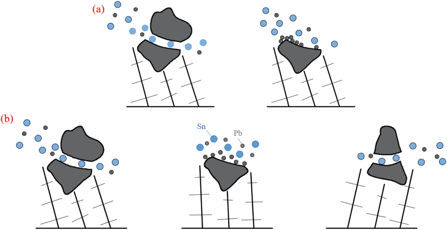
Solidification structure of round billets
According to the influence of different magnetic field stirring modes on the solidification structure of Sn-Pb alloy ingots, it can be seen that under the same magnetic field force, using alternate stirring mode can significantly improve the density and element uniformity of the ingot. In this study, in order to ensure the quality of round billets was only affected by the mould electromagnetic stirring process, all other continuous casting parameters were kept consistent. Such as the superheat of the tundish was controlled to approach 30°C during the experimental trials, and the water volume of the mould and the secondary cooling zone remained constant at 120 m3·h and 0.45 L·kg−1, respectively. Besides, this continuous caster does not have final electromagnetic stirrer equipment. So this paper mainly studied the effects of continuous stirring and alternate stirring mode on the solidification structure of the round billet under the same stirring current and frequency during the continuous casting process. Figure 14 is a schematic diagram of the cross-section solidification structure of round billets under different electromagnetic stirring modes, and Figure 15 shows the proportion of different solidification structure in billets under different electromagnetic stirring modes. The schematic diagram of the cross-section solidification structure of round billets under different electromagnetic stirring modes. (a) continuous stirring; (b) alternate stirring. Proportion of solidification structure of round billet under different stirring modes.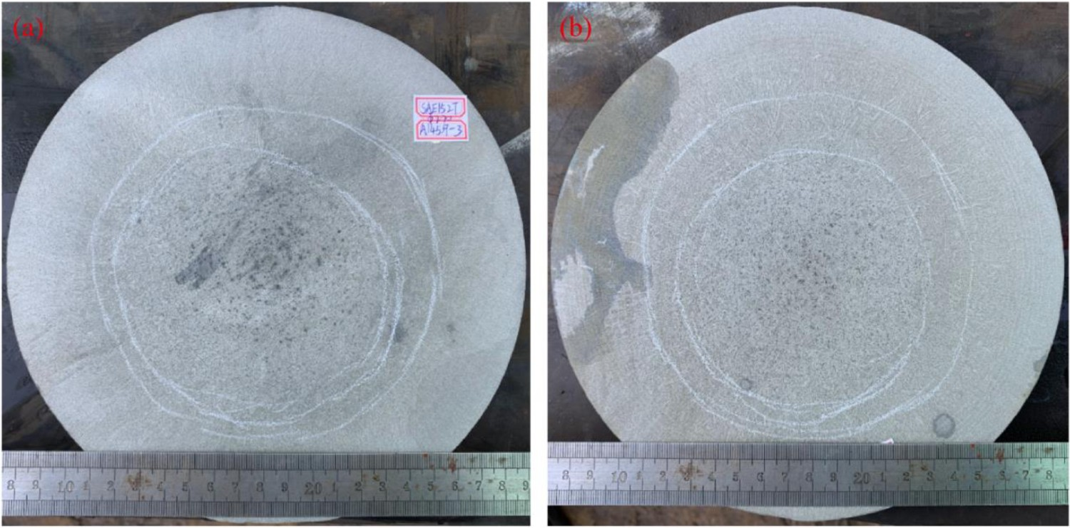
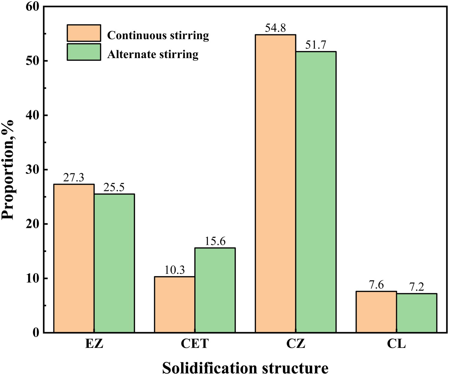
It can be seen from Figures 14 and 15 that when the electromagnetic stirring parameters are the same, different magnetic field stirring modes will have a greater impact on the proportion of solidification structure of the round billet. When the stirring current and frequency was 350 A and 3 HZ respectively, and the alternate stirring mode was adopted, the proportion of equiaxed crystal zone (EZ) and columnar crystal zone (CZ) of the round billet decreased from 27.3% to 25.5% and 54.8% to 51.7% respectively, but the proportion of columnar-to-equiaxed transition (CET) increased from 10.3% to 15.6%. The morphology of CZ of the round billet under different electromagnetic stirring modes is shown in Figure 16. As shown in Figure 16, when the alternate electromagnetic stirring mode was used, columnar crystal grow along the centre direction of the billet, rather than presenting a certain angle. Further, the transformation of CZ to CET was advanced and the proportion was larger. Disorderly arranged dendrites can reduce the concentration of elements moving to the centre of the billet with the solidification process of the billet. The reason for this phenomenon was that the alternate stirring mode was adopted, which makes the primary dendrites at the solidification front fall off and suspend in the molten steel during the growth of columnar crystals, hinders the growth of columnar crystal to the centre of the round billet, and advances the CET transformation. On the other hand, under the same stirring parameters, alternate stirring mode will change the rotation direction of molten steel. At the same time, compared with the continuous stirring mode, the efficiency of electromagnetic field acting on high-temperature steel was slightly lower, which slows down the dissipation of molten steel overheating to the outside, resulting in a decrease in the proportion of equiaxed crystal in the centre of the round billet. Morphology of CZ of the round billet under different electromagnetic stirring modes. (a) continuous stirring; (b) alternate stirring.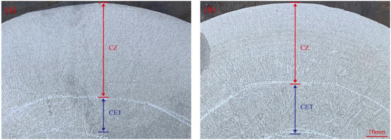
As shown by the experiments on Sn-Pb alloy ingots, the alternate stirring mode can significantly improve the uniformity of element distribution within the ingot. Since the segregation points in the core of the round billet will be inherited to the pipe during the subsequent rolling process to form a banded structure, which affects the quality stability of the product. So it is particularly important to reduce the segregation point in the core of the round billet [28–30]. Figure 17 is the comparison of spot segregation morphology in the core of continuous casting round billet under different electromagnetic stirring modes (the segregation point is in the red ring). The centre point of the round billet is the centre of the circle, and the range of 100 mm in diameter was selected as the statistical area. The number of spot segregation under different electromagnetic stirring modes was quantitatively analysed. The statistical results are shown in Figure 18. Morphology of spot segregation in the core of continuous casting round billet under different electromagnetic stirring modes. (a) continuous stirring; (b) alternate stirring. Statistical results of number of spot segregation in the core of continuous casting round billet under different electromagnetic stirring modes.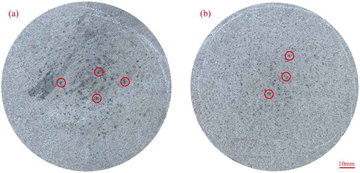
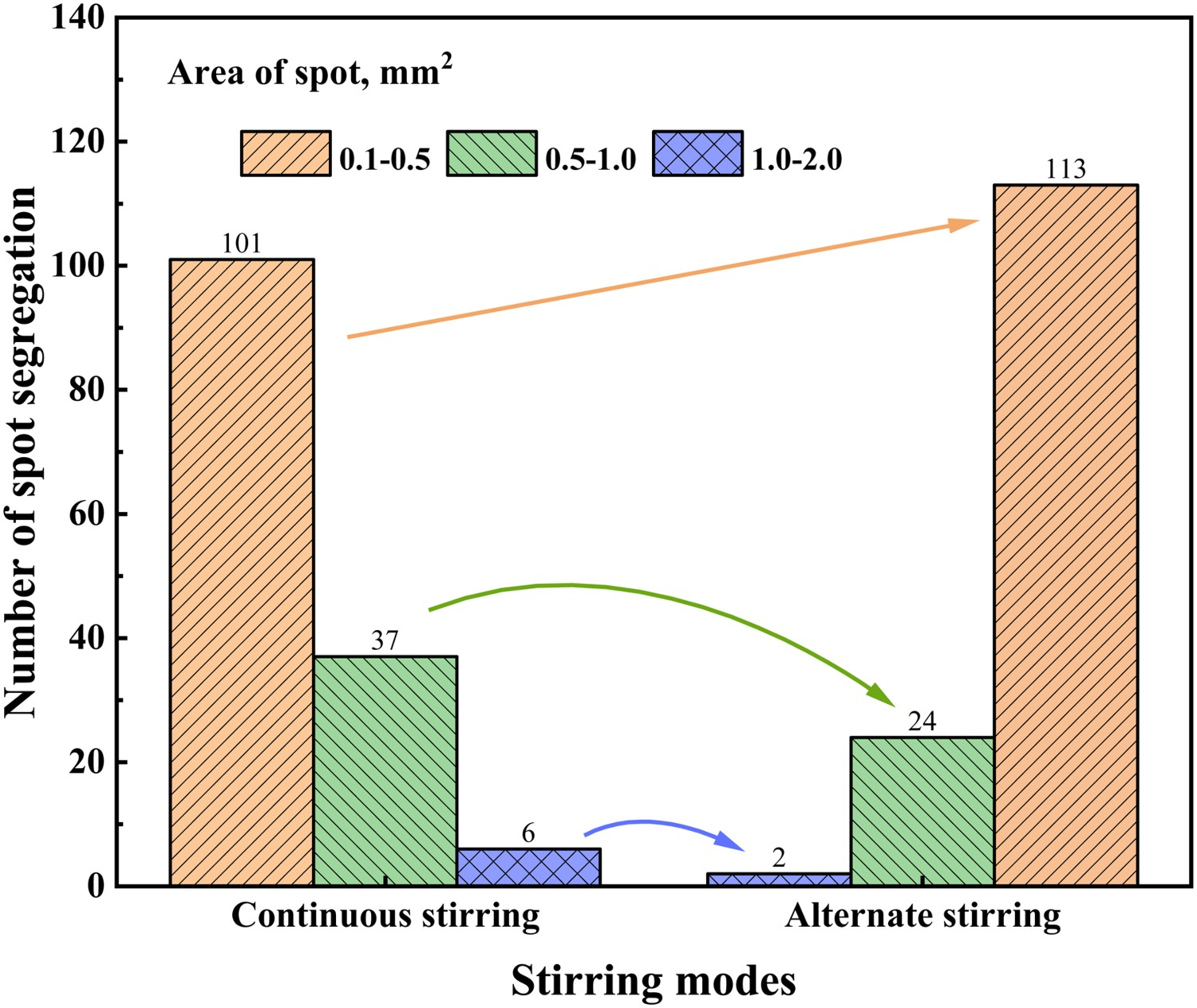
It can be seen from Figures 17 and 18 that under the two different mould electromagnetic stirring modes, there was mainly small spot segregation with an area of less than 0.5 mm2 in the central equixed crystal zone of the billet, and the larger spot segregation are mainly distributed near the centre of the billet. By counting the segregation points in the circle with a diameter of 100 mm, a total of about 140 typical segregation points were obtained for each sample. From the statistical results, it can be concluded that after the electromagnetic alternate stirring mode was adopted, the number of spot segregation with an area of more than 0.5 mm2 was reduced from 43 to 24, and the number of larger segregation point with an area of more than 1.0 mm2 was decreased from 6 to 2. However, the number of spot segregation with an area less than 0.5 mm2 increased from 101 to 113. Therefore, after the mould electromagnetic stirrer was adjusted from continuous stirring mode to alternate stirring mode, the number of spot segregation with large size in the core of the round billet was significantly reduced, and the spot segregation with small size were increased to a certain extent. This was consistent with the influence of different magnetic field stirring modes on the internal solidification structure of Sn-Pb alloy ingots. The spot segregation with small size were evenly dispersed in the core of the round billet, which improved the uniformity of the elements. Furthermore, according to the heredity relationship between the spot segregation in the round billet and the banded structure in the pipe, it can be inferred that less large-size segregation points in the core of the round billet can reduce the number of large-size banded structures in the pipe, thereby improving the quality stability of the pipe.
Conclusion
In this study, a permanent magnet stirrer was built to explore the effects of different magnetic field rotation speed and stirring modes on the solidification structure of Sn-Pb alloy ingots. Based on the results above, the magnetic field alternate stirring mode was applied to the actual continuous casting production process. The solidification structure and spot segregation morphology of round billets were statistically analysed, and the improvement effect of mould electromagnetic alternate stirring mode on the internal quality of continuous casting round billet was quantitatively evaluated in industrial production. The following conclusions were obtained: When the continuous stirring mode of magnetic field was adopted, and the stirring speed increases from 100 rpm to 200 rpm, the loose area in the core of the Sn-Pb alloy ingot decreased from 125 mm2 to 72 mm2. When the magnetic field adopted alternate stirring mode and the rotation speed was 200 rpm, the loose area of the ingot was only 21 mm2. It shows that under the same rotational speed, the magnetic field can improve the compactness of the core of the ingot by alternate stirring. The magnetic field-flow filed coupling model of the mould was established. By calculating the flow field and molten steel fluctuation level in the mould, the reasonable mould alternate electromagnetic stirring parameters were determined. Through simulate calculation, under the premise of stirring current and frequency of 350 A and 3 HZ respectively, the suitable stirring time of Φ220 mm SAE1527 round billet was clockwise stirring for 7 s, stopping for 3 s, and counterclockwise stirring for 7 s. When the stirring current and frequency were 350 A and 3 HZ respectively, the proportion of EZ in the round billet was reduced from 27.3% to 25.5% after the mould alternate electromagnetic stirring mode was adopted. However, the number of spot segregation larger than 0.5 mm2 was reduced from 43 to 26, which theoretically decreased the number of large-size banded structure in the pipe and improved its quality stability.
Footnotes
Disclosure statement
No potential conflict of interest was reported by the author(s).