
Abstract
In this study, the effects of different composition V-Mn-Cr inoculants on the microstructure and mechanical properties of GCI were investigated through Optical microscope (OM), Scanning electron microscope (SEM), Energy-dispersive spectroscopy (EDS), X-ray diffraction (XRD), etc. The results showed that the optimum quantity of inoculant was 7% V, 1% Mn and 6% Cr, and compared with the commercial inoculant samples, the tensile strength, Brinell hardness, and elastic modulus of the V-Mn-Cr inoculant samples increased by 16.7%, 14.2%, and 12.8%, respectively. V-Mn-Cr inoculants were found to refine austenite, graphite, pearlite and eutectic cells size, reduce pearlite lamellar spacing, and increase pearlite and eutectic cells number, thus improving mechanical properties. In addition, graphite nucleation substance may consist of oxides (SiO2, FeO, Cr2O3), carbides (SiC, TiC), sulfides (MnS, FeS), and XO·SiO2 silicates (X: Mn, Fe, Ca).
Introduction
As the most widely used cast iron material, grey cast iron (GCI) is broadly used in shipbuilding, automobile, machine tools, and other manufacturing industries due to its good casting performance, vibration resistance, wear resistance and cutting performance [1–3]. It is very important to improve the performance of GCI with the increasingly high requirements [4,5]. Among the variables that influence the mechanical properties of GCI are reasonable chemical composition, heat treatment, inoculation treatment, and more [6–10]. Inoculation treatment is a common method to obtain high-performance GCI, which is favourable for the nucleation of graphite and promotes the formation of lamellar pearlite [11].
Many investigators have researched the inoculation performance of inoculants, such as Fe-Si inoculants, rare-earth (RE) inoculants, Sr-Si inoculants, Ba-Si inoculants and so on [12–15]. For example, Riposan et al. [12] declared that Al-Zr-Fe-Si inoculant decreased the eutectic undercooling and recalescence, improved graphite characteristics, and avoided carbides, thus increasing the tensile properties of GCI. Li et al. [13] indicated that RE-containing inoculants could enhance the quality of castings, which was attributed to RE elements eliminating the hazards of trace elements, improving the morphology of graphite, and increasing the number of eutectic cells. He et al. [14,15] demonstrated that Sr-Si inoculants and Ba-Si inoculants could improve the morphology of graphite and increase the number of eutectic cells, resulting in an increase in the tensile strength and hardness of GCI.
Alloying elements usually need to be added to the inoculant to obtain excellent castings, such as carbide-forming elements V, Mn, and Cr that promote pearlite formation and refine pearlite, thus they have been investigated in GCI [16–18]. For instance, Wang et al. [16] revealed that the carbides generated by V could play a role in refining the grain and strengthening the matrix microstructure, significantly enhancing the tensile strength and wear resistance of GCI. Fu et al. [17] signified that the addition of Cr, Ba-Si, and Fe-Si composite inoculants improved microstructure uniformity and increased the tensile strength and hardness of GCI. Wang et al. [18] pointed out that adding a certain amount of Mn and CaSi inoculants could obviously increase the inoculation effect, refine pearlite, and improve the morphology of graphite, thereby enhancing the mechanical properties.
At present, the technology level of GCI has improved greatly with decades of development, but less research has been done on the effects of V, Mn, and Cr in the inoculants on the performance of GCI. Therefore, the purpose of this work was to investigate the influence of different compositions V-Mn-Cr inoculants on the microstructure and mechanical properties of GCI by orthogonal experiment. The corresponding mechanism for the improvement of the performances of GCI was also discussed, providing the theoretical basis for the development of GCI application.
Experimental procedure
Experimental details
The raw materials composition of GCI is shown in Table 1. These raw materials were melted in a 100 Kw medium frequency induction furnace at 1480–1500°C. Subsequently, the melt was inoculated to adopt the method of in-ladle inoculation. The added amount of inoculant (particle size of 0.5∼1.0 mm) was 0.4% of melt mass. The melt was poured into the resin sand molds with the geometry shown in Figure 1. The pouring temperature is 1360∼1370°C. Before pouring, a small amount of melt was poured into a metal mold to produce white cast iron specimens, which were used for chemical composition verification. The results of chemical analyses are shown in Table 2. Geometry of standard sand mold single cast test bar (mm). Chemical composition of raw materials (wt-%). Chemical composition of GCI samples (wt-%).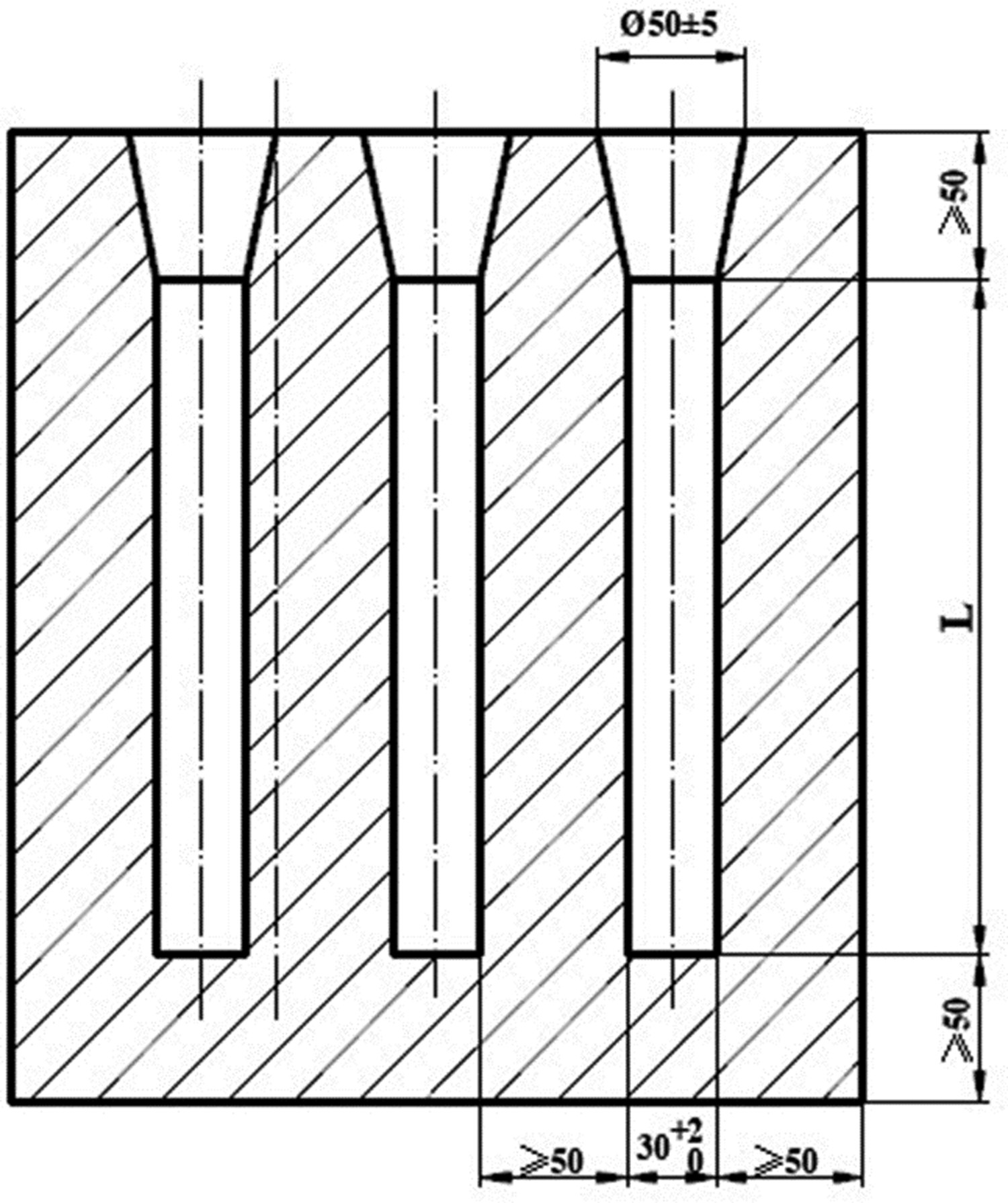
Orthogonal experimental design of inoculant composition (wt-%).
Microstructure analysis
Metallographic samples (Φ20 mm × 10 mm) were obtained from the castings. Before testing, the specimens were polished with coarse-to-fine grit emery papers, washed with distilled water, and dried in air. After polished, the graphite microstructure was directly observed by an Optical microscope (OM), then the specimens were etched with 4% nitric acid alcohol solutions, and the matrix microstructure was observed under OM. Subsequently, after being re-polished, the specimens were etched with 4 g copper sulfate, 20 ml concentrated hydrochloric acid, and 20 ml distilled water, and the eutectic cell microstructure was also observed through OM. Finally, the sample was placed in a barrel resistance furnace, heated to 860 °C at a heating rate of 1000 °C/5 h, kept for 35 min, and then cooled to 600 °C with the furnace, and then the sample was taken out and cooled to room temperature. After the heat treatment, metallographic specimens were prepared, a 4% nitric acid alcohol solution was used for external corrosion, and the austenite dendrites morphology was observed by OM.
The morphology of matrix, graphite, and fracture was also characterised by a Scanning electron microscope (SEM), equipped with the Energy-dispersive spectroscopy (EDS) system for elemental analysis and quantitative mapping.
The phases of the microstructures in GCI were determined by X-ray diffraction (XRD). The specimens were placed in a continuous scanning X-ray diffractometer using a Cu target with a tube voltage of 40 kV and a tube current of 20 mA, the scanning speed was 4°/min, and the diffraction angle was 20° to 90°.
Performance testing
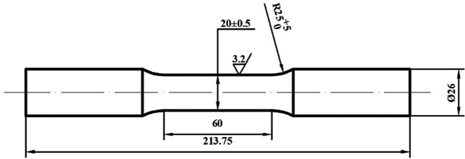
The tensile standard specimen of GCI is shown in Figure 2, which were got from the castings. Three tensile tests were performed for each group, and the average was valued as the final result. Furthermore, the elastic modulus of the samples was calculated according to the following formula: Specimen of the tensile test (mm).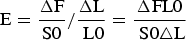


The hardness specimens (Φ20 mm × 20 mm) were obtained from the castings, and the specimens were measured by the 320HBS-3000 type digital display Brinell hardness tester. Using a hardened steel ball indenter (diameter of 10 mm), the loading time and dwell time were 10 and 12 s under constant force (3000 kg), respectively. Five points were tested randomly for each group of the sample, and the average value was calculated as the final result.
Results
Orthogonal experiment results
Results of orthogonal experiment.
Optimisation of orthogonal experiment results.
Mechanical properties of optimal schemes.
Microstructure
The graphite (not etched) microstructure of GCI samples inoculated with different inoculants is shown in Figure 3. It is evident the 7%V-1%Mn-6%Cr inoculant has a positive effect on the bending and refinement of graphite. According to GB/T 7216-2009 [19], the graphite shape and length are evaluated mainly by graphite morphology and size, respectively. As shown in Figure 3(a), the graphite shape is A type and few of D type (about 10%), and the graphite length is 3∼4 level (12∼50 mm). As shown in Figure 3(b), the graphite shape is A type, and the graphite length is 4 level (12∼25 mm). Graphite morphology of the different inoculant GCI samples. (a) Commercial inoculant, (b) 7%V-1%Mn-6%Cr inoculant.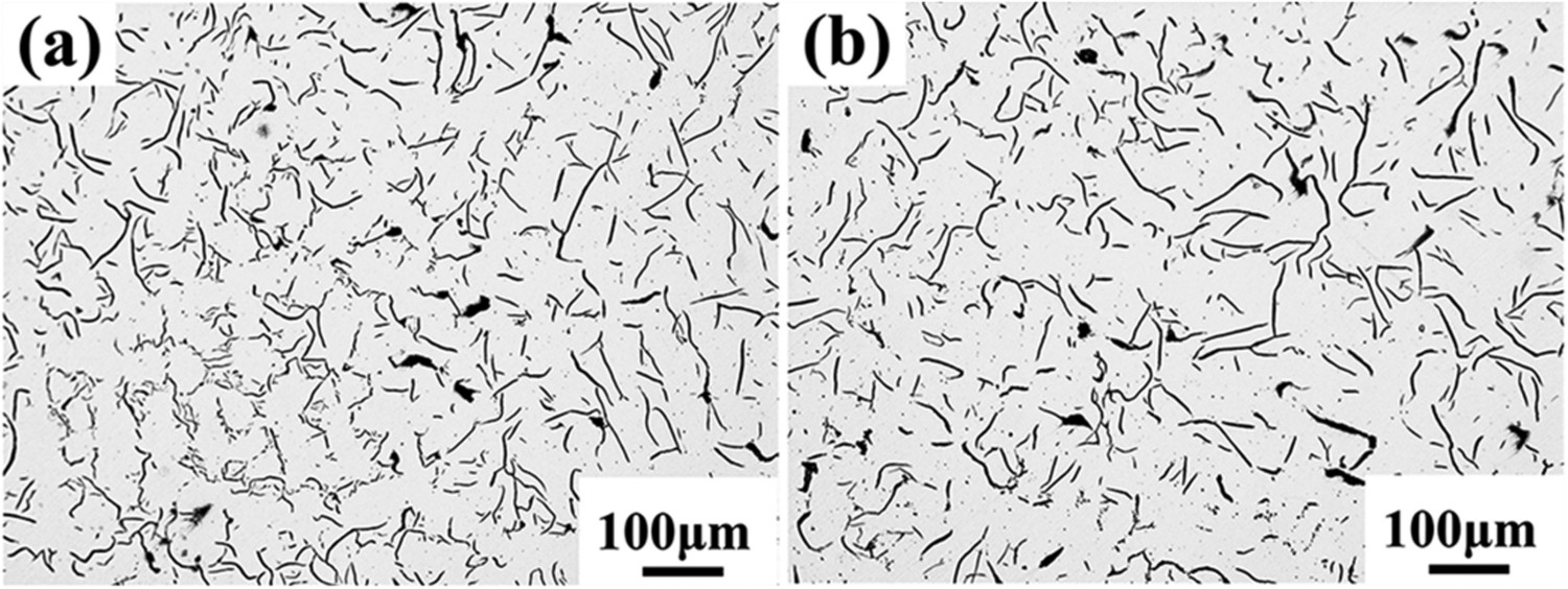
To study the composition of graphite, EDS point analysis was performed on the specimens inoculated with 7%V-1%Mn-6%Cr, and the results are presented in Figure 4. As shown in Figure 4(b), the elements in point A are C, Si, S, Ti, V, Cr, Mn, and Fe. As shown in Figure 4(d), the elements in point B are C, N, O, Si, Mn, and Fe. EDS analysis indicates that the graphite may be made up of MnS, FeS, TiC, SiC, Cr2O3, FeO, etc. Meanwhile, SiO2 and XO·SiO2 silicates (X: Mn, Fe, Ca) may exist. SEM morphology and EDS spectra of graphite in the 7%V-1%Mn-6%Cr inoculant samples. (a) The morphology, (b) The EDS analysis of point A. (c) The morphology, (d) The EDS analysis of point B.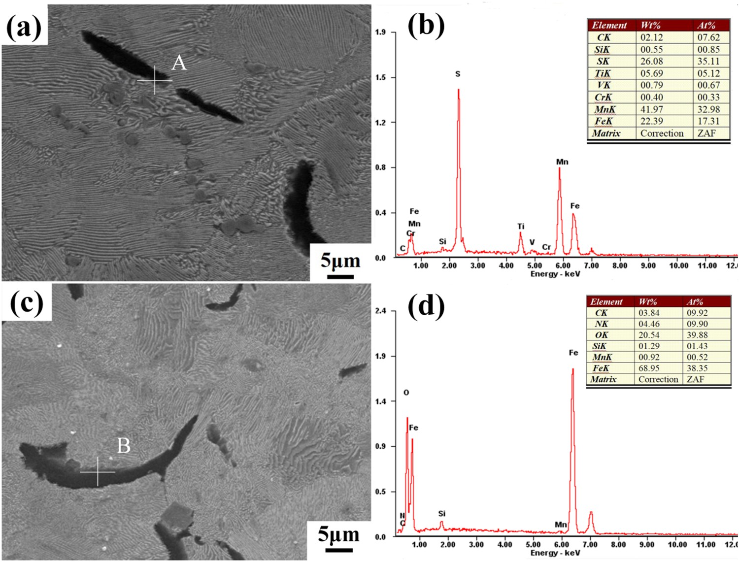
Figure 5 shows the matrix (etched) microstructure of GCI samples inoculated with different inoculants. The microstructures both consist mainly of flake graphite, ferrite, and pearlite. The white area is the ferrite microstructure, and the grey area is the pearlite microstructure. It can be seen that the quantity of ferrite decreases slightly, and pearlite increases slightly in the 7%V-1%Mn-6%Cr inoculant samples, compared with the commercial inoculant samples. Matrix morphology of the different inoculant GCI samples. Commercial inoculant, (b) 7%V-1%Mn-6%Cr inoculant.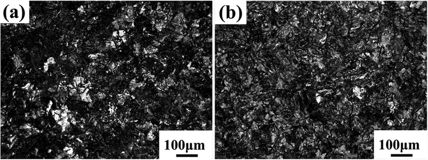
To observe the lamellar spacing of pearlite, SEM analysis (1000×) was performed on samples, and the results are presented in Figure 6. It is obvious that graphite end passivation, the lamellar spacing of pearlite decreases, and the density increases in the 7%V-1%Mn-6%Cr samples. The pearlite lamellar spacing is 0.45-0.6 µm in Figure 6(a) and 0.35-0.5 µm in Figure 6(b). SEM morphology of the different inoculant GCI samples. (a) Commercial inoculant, (b) 7%V-1%Mn-6%Cr inoculant.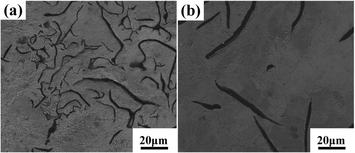
To determine the phase components of the GCI sample, XRD analyses was conducted on the samples inoculated with 7%V-1%Mn-6%Cr, and the result is displayed in Figure 7. The microstructure may contain mainly α-Fe, TiC, SiC, VC, FeS, MnS, Fe3O4, Cr2O3, FeSiO3, and MnSiO3 phases. X-ray diffraction pattern of the 7%V-1%Mn-6%Cr inoculant specimen.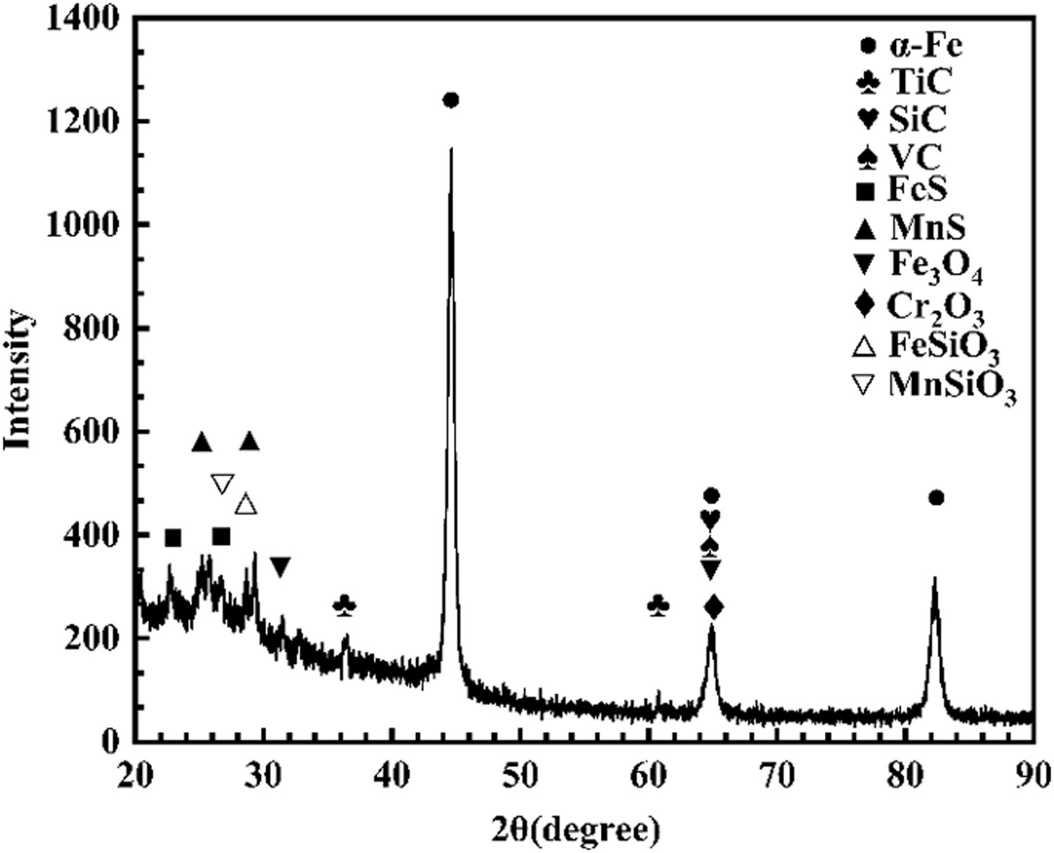
Figure 8 shows the primary austenite dendrites morphology of GCI samples inoculated with different inoculants. It can be seen that the amount of primary austenite dendrites is lower, and dendrites arm spacing is larger in the commercial inoculant samples, as shown in Figure 8(a). However, primary austenite dendrites amount increases significantly, dendrites arm spacing decreases significantly, and form a complex space structure in the 7%V-1%Mn-6%Cr inoculant samples, as shown in Figure 8(b). Primary austenite dendrites morphology of the different inoculant GCI samples. (a) Commercial inoculant, (b) 7%V-1%Mn-6%Cr inoculant.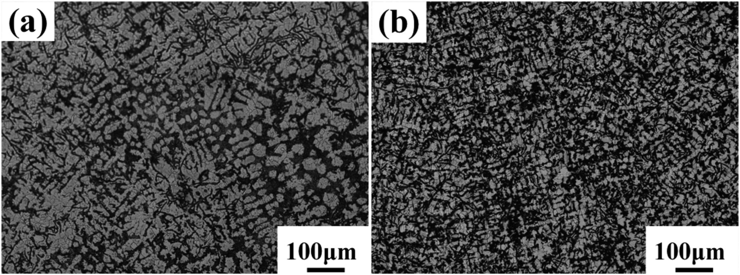
The eutectic cells microstructure of GCI samples inoculated with different inoculants is shown in Figure 9. It is obvious that in the 7%V-1%Mn-6%Cr inoculant samples, the eutectic cells number increases and the size reduces. The average size of eutectic cells is 470 µm in Figure 9(a) and 370 µm in Figure 9(b). Eutectic cell morphology of the different inoculant GCI samples. (a) Commercial inoculant, (b) 7%V-1%Mn-6%Cr inoculant.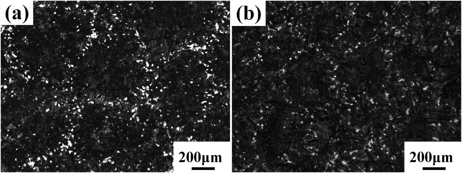
Discussions
Formation mechanism of graphite
Studies have shown that the formation of graphite crystals is mainly by heterogeneous nucleation [20–22]. According to heterogeneous nucleation theory [23], heterogeneous nucleation of graphite mainly includes carbides, sulfides, oxides, nitrides, silicates, and unmelted graphite. Thermodynamic calculations were performed to predict the primary reaction occurring after the inoculant was added. According to thermodynamic theory [24], the following reactions might take place.


The Gibbs free energy at constant temperature and constant pressure can be expressed:


Gibbs free energy (


According to heterogeneous nucleation theory, schematic representation of heterogeneous nucleation is shown in Figure 10, and the calculation of the work of heterogeneous nucleation ( Schematic diagram of heterogeneous nucleation [23].
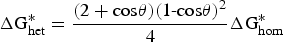
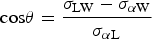


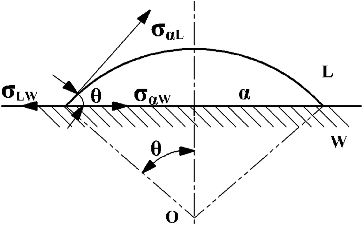
It is easy to know the work of heterogeneous nucleation (


According to the results of Table 7, SiO2, SiC, FeO, FeS, MnS, TiC, Cr2O3 and XO·SiO2 silicates (δ 


Effect of V-Mn-Cr inoculant on microstructure and performances
The addition of V-Mn-Cr inoculant increases the carbon activity and provides the substances of graphite nucleation, which increase the graphite nucleation rate, thus improving the graphite microstructure (Figure 3). During austenite transformation, the carbide-forming elements V, Mn, and Cr in the inoculant can promote the nucleation of cementite, leading to an increase in the amount of pearlite (Figure 5). In addition, Mn can increase the eutectoid undercooling which accelerates the eutectoid reaction process, thus enhancing the tendency of austenite to pearlite transformation that reducing the lamellar spacing of pearlite (Figure 6), and Cr elements further improve the complexity of dendrites (Figure 8). Consequently, the eutectic graphite count raises with the addition of V-Mn-Cr inoculant, which increases eutectic cells number (Figure 9), resulting in an improvement of the mechanical properties of GCI.
Conclusions
The microstructure and mechanical properties of GCI with V-Mn-Cr inoculants were investigated through OM, SEM, EDS, etc. The following main conclusions could be drawn: The optimal composition of the inoculant was determined by orthogonal experiment as 7% V, 1% Mn and 6% Cr (wt-% of inoculant), and the tensile strength, Brinell hardness, and elastic modulus of the V-Mn-Cr inoculant samples were 356 MPa, 233 HB, and 149 GPa, respectively. Compared with the commercial inoculant samples, the tensile strength, Brinell hardness, and elastic modulus of the V-Mn-Cr inoculant samples increased by 16.7%, 14.2%, and 12.8%, respectively. V-Mn-Cr inoculant can refine the microstructure of GCI, improve graphite morphology, increase pearlite and eutectic cells number, and reduce pearlite lamellar spacing, resulting in an improvement of the mechanical properties. V-Mn-Cr inoculant can provide the substance of graphite nucleation. The substrate of the graphite nucleation may consist of oxides (SiO2, FeO, Cr2O3), carbides (SiC, TiC), sulfides (MnS, FeS), and XO·SiO2 silicates (X: Mn, Fe, Ca).
Footnotes
Acknowledgements
The authors acknowledge and thank the Zhengzhou University Analytical and Testing support.
Disclosure statement
The authors declare that they have no known competing financial interests or personal relationships that could have appeared to influence the work reported in this paper.