
Abstract
Different ways of investigation were applied to address the main difficulties of electrolytically refining the tin-based lead-free soldering waste materials in chloride solutions. The characteristics of electrorefining and the phenomena of electrocrystallisation have been targeted by examining the electrode processes with different copper and silver concentrations in the anodes. Galvanostatic experiments were carried out using a specially developed system detecting the changes in the electrode masses continually, complemented by the recording of the electrode potentials. In order to clarify the main cathode and anode processes, further investigations were carried out by the potentiodynamic technique. Galvanostatic results pointed out the causes of current losses and rough deposit structure. Potentiodynamic examinations have demonstrated the strong influence of material transport on the electrode processes. Nevertheless, with a quasi-optimised procedure, cathode tin of higher purity than technical standards could be achieved from the soldering waste material in a conventional cell.
Keywords
Introduction
As a result of strict regulations, the electronic producers are obliged to apply lead-free materials for soldering and coating. The most common alloys contain a high percentage of tin, combined with silver and copper. Other components, like bismuth or nickel are also considered. The melt of this material is aggressive towards the copper parts of the electronic devices, thus the soldering or coating bath soon requires dilution. A further difficulty is the higher tendency of dross formation. Therefore, the frequency of skimming the bath and the amount of collected dross, containing a large proportion of the metal has increased, and the requirement for pure tin or copper-free tin master alloys is rapidly increasing. Therefore, recycling gains special importance. According to the conventional practice, summarised by Halsall (1989), tin scrap is collected from the electronic industry and transported to an existing tin smelter. Our aim is to develop a hydro-electrometallurgical method of recovering pure tin and separate the alloying elements in a suitable form for further recovery.
The primary dross collected from the soldering or tin coating baths used in the electronic industry needs partial melting to allow careful skimming of a secondary ‘dry’ oxide dross. With careful temperature control at this preliminary step, iron contamination can be removed almost completely according to the eutectic compositions, as pointed out by Takemoto, Uetani and Yamazaki (2004). However, copper concentration can be reduced only to approximately 0.8 wt-% in the eutectic melt, while the silver content, influencing the microstructure of the most often applied Sn–Ag–Cu soldering alloy, as shown by Reid, Punch, Collins and Ryan (2008), is virtually unaffected. In order to separate the remaining copper and silver, we have cast the scrap alloy into the shape of flat anode slabs to be applied for electrorefining. The nobler elements of more positive electrode potential than that of tin may remain in a separate slime phase at the surface of the anode. The more reactive impurities, on the other hand, are not significantly present in the alloy. Even if they are dissolved, with controlled electrolyte composition, they are not deposited at the cathode. An acid electrolyte solution is preferred because it does not require high temperatures and the dominant species are Sn(II) instead of the higher charged Sn(IV) in alkaline baths. Although the conventionally applied acidic alternative is sulphate based in primary refining, described by Weigel and Zetsche (1974), it incurs considerable initial costs by the high requirement of special components, like cresylic-phenolic sulphonic acid for stabilising the solution and β-naphthol and gelatine as levelling agents. In this way, the cathode tin structure is still imperfect and the current efficiency is low.
On the other hand, special components may not be required for stabilising tin chloride–hydrochloric acid solutions, but the crystal structure of the deposit is hardly affected by organic inhibitors. The solubility of tin chloride is excellent and as suggested by Rimaszéki, Kulcsár and Kékesi (2012a), the HCl concentration can be kept as low as 1 mol L−1.
The chloride system also introduces some specialties caused by the formation of tin chloro-complexes, whose relatively high stability is shown by compilations of Sillén and Martell (1964) and Högfeldt (1982). However, solution stability may be impaired if the Sn(IV) concentration rises, resulting in hydroxide or stannic acid precipitation. Oxidation may arise from the effects of ambient air or by the irregular conditions of the anode. However, Cl− activity by forming complex ions

Even though Sn(IV) species are stabilised, their formation in the anodic process is unfavourable because of the higher specific charge involved, resulting in a higher electric energy requirement. Ambient air can also oxidise the dissolved Sn(II) species


Rimaszéki et al. (2012a) examined the thermodynamic feasibility of reactions (1)–(3) by determining the equilibrium distribution of tin among its various species at different redox potentials and chloride ion concentrations applying a specifically developed software (ROCC). The simulation has shown that the tetravalent form is stable by air oxidation and the divalent will prevail if metallic tin is present. If the solution is in contact with both air and metallic tin, the total Sn concentration can increase by the combined effect of reactions (2) and (3). Therefore, the electrolytic refining of tin in HCl solutions requires counteracting the tendency of Sn(II) oxidation, the control of Sn concentration and the optimisation of electrolysis parameters.
Adequate conditions have been found with 10 g dm−3 Sn and 1 M HCl composition of the electrolyte, and with as high apparent current densities as 1000 A m−2, tin deposits of 99.99% purity could be obtained (Rimaszéki, Kulcsár and Kékesi 2012b). Chloro-complexation may also influence the cathodic reduction. If it is in the form of slowing the rate of charge transfer, decreasing the exchange current density, it may result in smoother deposits as well. According to Winand (1992), the morphology of the deposit is fundamentally controlled by the overpotential and the degree of inhibition.
Special techniques of current modulation have also been investigated, but the difficulties caused by the formation of dendritic deposits could not be overcome in the experiments of Behmer, Krajewski and Krüger (1983) and Rimaszéki et al. (2012b) even by applying various periodic current reversal techniques or by implementing extremely short current impulses (Kulcsár, Dobó and Kékesi 2013). Therefore, further research was necessary into especially the cathodic processes of tin electrorefining in hydrochloric media. Optimisation of the conditions should rely more on a detailed study of the electrode processes. For this purpose, the changes of the electrode masses need to be recorded and compared to the potential and current readings.
The purity of the produced metal depends on the kind and concentration of the impurity elements in the anode and in the electrolyte solution. The impurity elements of lower electrode potentials than that of tin (e.g. Fe, Zn, Ni, Co … ) are dissolved from the anode material but they remain in the solution until their relevant critical activity at the cathode surface is reached
 and
and
 are the standard electrode potentials of tin and the impurity element, respectively, vi is the ionic charge, F is the Faraday constant, R is the general gas constant, T is the temperature in kelvins and aSn(II) stands for the activity of the Sn(II) ions directly at the surface of the cathode. Higher tin concentrations in the electrolyte are favourable for avoiding impurity deposition; however, it may be unfavourable for the anode process and the stability of the solution. The rising concentration of the minor dissolving impurities on a long term can be avoided by circulating the solution out of the cell and conditioning it. In the most common Sn–Ag–Cu lead-free soldering alloy, the alloying elements have electrode potentials higher than that of tin, therefore they can be retained in the anode slime, usually formed also of particles of the matrix metal. Owing to the components of nobler elements (like Ag), this byproduct is also of economic interest.
The tendency of dendrite formation at the cathode, shown by Rimaszéki et al. (2012b) suggests that the diffusion of the ionic species of tin is relatively slow, adversely affecting both the cathodic and the anodic processes. Electrocrystallisation may be disturbed by the depletion of the cathode surface of the tin ions also dissolution may be hindered. The latter effect does not only cause the danger of oversaturation of the electrolyte adjacent to the anode, but it raises the anode potential, resulting in eventually more Sn(IV) species produced. As tin concentration drops near the cathode, hydrogen evolution or impurity deposition can take place. Hydrogen bubbles adhering to the cathode surface may partially block the active sites enhancing the growth of projecting long crystals. This is considered the most important practical difficulty of the application of hydrochloric acid-based electrorefining for the processing of soldering waste materials. However, the possible increase of the tin concentration by the combined effect of reactions (2) and (3) also has to be taken into consideration by proper conditioning of the solution. Our aim was to target the difficulties of the electrode processes by various techniques of examination specifically developed for the investigation of tin electrorefining, with a focus on the irregular cathodic deposition of tin.
Experimental procedure
The electrode processes of tin refining were studied under galvanostatic conditions using a specially developed continuous mass and potential monitoring system, and also by the potentiodynamic technique. The two different measuring methods gave relevant information on the characteristic behaviour of the tin electrode in the tin chloride–hydrochloric acid electrolytes. The stock solution was prepared by dissolving pure tin crystals – preliminary grown on cathodes – in reagent-grade concentrated hydrochloric acid at boiling temperature in a glass reactor equipped with a reflow condenser.
The soldering waste materials – obtained from Jabil Circuits Hungary Co. Ltd, Vishay Electronics Hungary Co. Ltd and Glob-Metal Co. Ltd – containing the metals in different concentrations were partially melted in carbon-clay crucibles, while the temperature was carefully controlled and the secondary oxide dross was collected by skimming the melt surface (Fig. 1a).
Raw materials and electrodes of tin electrorefining, a molten soldering waste material; b impure anode; c fresh and used cathodes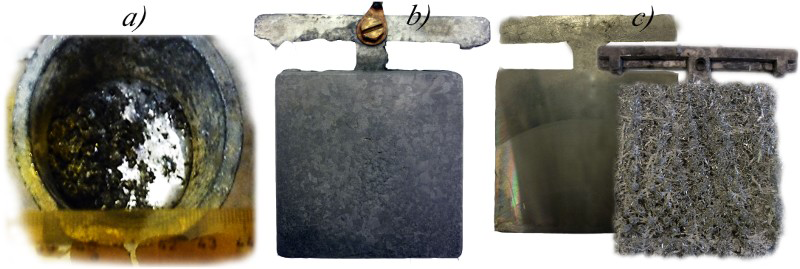
Galvanostatic experiments
The molten metal was cast into anode moulds of steel and cooled in air. The anode (Fig. 1b) of 6 × 6 cm effective area and 15-mm thickness was placed in a cubic glass cell of 450 cm3 volume. The cathodes (Fig. 1c) of the same surface area as the anodes were cast from a pure tin bath in similar moulds. The active surface was freshly machined for each run and the reverse side was masked. During the electrolysis, a loose structure of dendrites deposited at the operating cathode surface facing the anode. The in situ mass measurement was continued through the first 5 min after starting the current, but for testing the purification efficiency, the electrolysis run was continued for 12 h.
Unlike for the anode, current densities of the cathode can be considered only apparent, referring to the geometric starting surface, as the deposition of loosely packed crystals constitute an uncertain actual surface area (Fig. 1c). Based on the preliminary results by Rimaszéki et al. (2012a, 2012b), the examinations were carried out in the Sn concentration range of 5–40 g dm−3, and the HCl concentration was set to 1 mol dm−3, found sufficient to assure solution stability. The concentration of the Sn(II) ions was determined directly by iodometry, whereas the total tin concentration could be analysed in the same way after complete precipitation of the dissolved tin species with aluminium powder, followed by re-dissolution in boiling concentrated HCl. Earlier experimental findings by Rimaszéki et al. (2012a) have proved that the oxidation of Sn(II) species by ambient air is so slow, that it may not disturb the analysis, and the Sn(II) form is dominant while the solution is in contact with metallic tin of relatively large specific surface area.
For the continuous mass monitoring, we used a Kern KB-240-N type digital scales of 0.001 g sensitivity equipped with a bottom suspension adapter, as shown in Fig. 2. This measurement required stationary solutions in the refining cell. The changes in the potentials of the electrodes were measured versus a saturated calomel reference electrode during the long-term galvanostatic experiments.
The electrolysis system with continuous mass measurement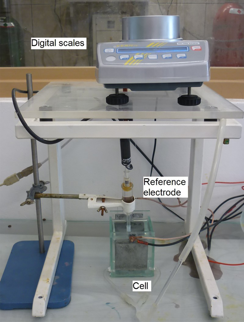
The measured weight was corrected for the buoyancy in the electrolyte solution, according to the density (ρ, g cm−3) function determined preliminarily for the SnCl2 (1 M HCl) solution

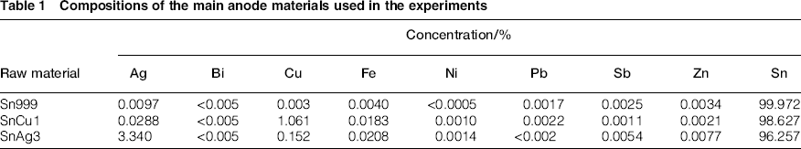
Compositions of the main anode materials used in the experiments
Potentiodynamic experiments
The potentiodynamic experiments were focused on studying the characteristics of electrocrystallisation. We applied a cubic cell of 100 cm3 volume, filled with the prepared SnCl2–HCl solutions of various concentrations at room temperature. The reference potential was provided by a saturated calomel electrode, equipped with a Luggin-capillary pointed at the centre of the tin working electrode of 1 cm2 active surface area. The counter electrode was also made of pure tin, so as to avoid significant changes in the solution composition even after several runs of the measurement. The current was supplied by an Elektroflex EF 435C potentiostat, and recorded by a computer, running the Iemas 1.06 software. The measurements were run either with 5 mV/0.5 s potential steps or a continuous 100 mV s−1 rate of polarisation. The former technique was used for the chrono-potentiometric studies, where the rate of polarisation was optimised to give the most points in the monotonous range of the curves. Generally, short cathodic cycles were applied because of the changing conditions caused by rapid crystal growth.
The HCl concentration was usually 1 mol dm−3, which already allowed a safe stability of the solution even in contact with ambient air. In specific experiments, the electrolytes contained 0, 2.5, 5, 10, 20 or 30 g dm−3 Sn. As assured by the solution preparation, the predominant species were Sn(II) in the electrolyte, analysed by iodometry and corrected if needed. Stirring was set at 0, 100, 200, 350, 500, 650, 800 rev min−1. Macro-photographs of the work electrode surfaces were taken during and after each run. A large number of data collected from hundreds of experimental runs were evaluated by a specifically developed program (using the Microsoft Visual Basic platform) on spreadsheets.
As the deposited tin crystals usually developed fast with a loose structure, the surface of the cathodically polarised working electrode could quickly change. Therefore, instead of the conventional polarisation curves chrono-potentiometric results were evaluated for the cathodic direction in some cases, also taking the macro-photographs of the deposit into account.
Experimental results and discussion
Short-term galvanostatic investigations
The type of dissolved tin species may directly depend on the potential of the anode, forced on it by the regulated electric supply setting the desired current. Figure 3a shows the measured anode potentials expressed versus the standard hydrogen electrode in a solution of 40 g dm−3 Sn and 1 M HCl at different applied current densities. These results can be compared to the equilibrium values computed from the electrode potentials and complex stability constants compiled by Sillén and Martell (1964) and Högfeldt (1982), illustrated in the E-pCl− diagram of Fig. 3b. The equilibrium Sn(IV)/Sn(II) redox potential in the solution of 1 M HCl concentration is approximately 0.12 V, as marked with the dashed arrow. If the current density is above 1000 A m−2, the measured potentials are higher than the equilibrium potential for the Sn(IV)/Sn(II) system, therefore the dissolution of the metal may directly produce Sn(IV) species, which may react with the tin particles at the surface of the anode – forming the slime layer – according to equation (3). With continued electrolysis, as the anode surface gets gradually rougher, the anode potential may decrease.
Comparison of measured and equilibrium potentials, a anode potentials at different current densities; b the equilibrium E-pCl− diagram of the tin species in chloride solutions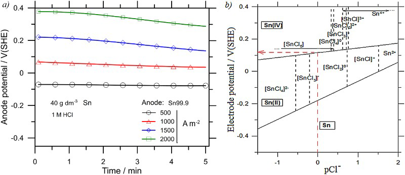
The changing masses of the electrodes were recorded during the electrolysis. The results obtained for the anodes made of different tin alloys under the conditions of 2000 A m−2 current density in a 5 g dm−3 Sn–1 M HCl solution are as plotted in Fig. 4a. The measurement was continued after switching the power supply off, and these results referring to a pure tin (99.9%) anode after electrolysis in a 40 g dm−3–1 M HCl solution with different current densities are as shown in Fig. 4b. Virtually all the anode materials show similar dissolution characteristics. The differences may be within the experimental error margin. The mass loss even continues – although at a significantly lower rate – after the current is stopped. This is especially so after the electrolysis with higher current densities and in electrolytes of higher tin concentrations. The main reason behind this phenomenon is assumed to be the reaction of the formerly generated Sn(IV) species with the metal body of the electrode, as expressed by equation (3). As this effect is amplified by the applied current density, it also proves the possible Sn(IV) generation at the anode, deduced from the potentials as illustrated in Fig. 3.
Mass changes of anodes during a and immediately after b electrolysis in the 1 M HCl stationary solutions, a electrolysis with different anode materials; b mass changes of the pure tin anodes recorded immediately after shutting down different current densities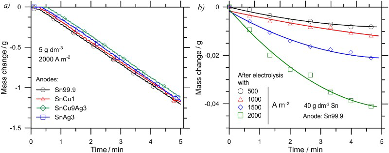
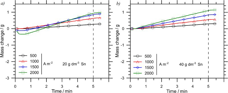
The cathode produced surprising initial mass changes during the first few minutes of electrolysis in the 1 M HCl electrolyte solutions of lower (5 and 10 g dm−3) Sn concentrations. Figure 5 shows cathodes – instead of gaining – initially losing weight especially at higher current densities applied. This was caused by the hydrogen bubbles evolved at the fresh cathode surfaces. The tiny hydrogen bubbles adhere to the surface and exert an extra buoyancy force, which is indicated as a mass loss by the in situ measuring system. At the lowest examined 500 A m−2 current density, this effect is relatively weak and it is approximately balanced by the simultaneous tin deposition, but at higher current densities the apparent weight loss is higher. With continued electrolysis, when the effective surface area is increased by the roughly deposited crystals, the hydrogen evolution subsides. The initial deposition of tiny hydrogen bubbles may block a significant portion of the cathode surface and thereby may contribute to the development of irregular electrocrystallisation too. Furthermore, the neutralisation of hydrogen ions can cause solution instability near the cathode, resulting in precipitation if the concentration drops much below 1 mol dm−3. On the other hand, as shown in Fig. 6a and b, the start of the cathodic deposition is quite different in electrolytes of higher tin concentration. In the 20–40 g dm−3 Sn concentration range, the cathode mass starts increasing without any delay. However, this also means a looser and rougher dendritic structure, with the deposited crystals projecting far out from the surface. These results demonstrate how sensitive the tin electrode in HCl solutions is to the kinetic conditions.
Mass changes of the cathodes during the 5-min long electrolysis runs with different current densities and in an additional minute after the current was stopped in the 1 M HCl stationary solutions, a 5 g dm−3 Sn; b 10 g dm−3 Sn concentration Mass change of the fresh cathodes during the 5-min long electrolysis runs with different current densities and in an additional minute after the current was stopped in the 1 M HCl stationary solutions, a 20 g dm−3 Sn; b 40 g dm−3 Sn concentration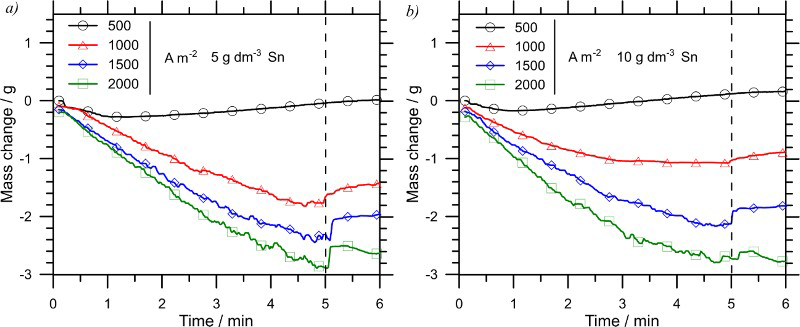
The characteristic cathodic deposits obtained with the mass monitoring experiments in stationary solutions are as compared in Fig. 7. The largest initial crystals were obtained with the solution of the highest examined tin concentration and higher apparent (referring to the original surface area) current densities. At the lowest current density, the increasing tin concentration tended to cause the growth of thin and long needles and whiskers. The overall comparison of the deposit structures may prove that the selection of 10 g dm−3 tin concentration coupled with apparent cathodic current densities in the 500–1000 A m−2 range in a stationary 1 M HCl solution is a good combination to be applied in a conventional cell. It has become obvious that in 1 M HCl stationary solutions and conventional planar electrodes, high tin concentrations are mainly responsible for the unfavourable deposition structures, especially if higher apparent current densities are applied.
Cathodic deposits obtained in 5-min long electrolysis runs with different apparent current densities, tin concentrations and 1 M HCl stationary solutions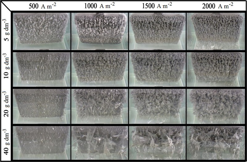
Potentiodynamic investigations
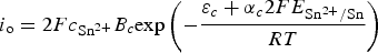
In order to study the cathodic deposition of tin from the chemically stable 1 M HCl stationary solutions further, the development of the current with the applied potential was examined by the potentiodynamic method too. The polarisation curves in Fig. 8 show great difference for the 1 M HCl stationary solutions of different Sn concentrations. With 10 g dm−3 Sn, the current density initially was rising in absolute value with the potential, but this tendency – corresponding to the Buttler–Volmer–Erdey-Grúz equation – was reversed and very soon a limiting current was reached. The exchange current density may not be stable as the concentration of the electro-active species at the cathode surface cannot be maintained. As suggested by Erdey-Grúz (1972), the approximate exchange current density io – at relatively high current densities – is in correlation with the concentration of the electro-active species
Polarisation curves and deposit structures observed in stationary solutions of 10 and 30 g dm−3 Sn concentrations, respectively (1 M HCl, 100 mV s−1 continuous polarisation) Chrono-potentiometric characteristics obtained with the 30 g dm−3 Sn, 1 M HCl stationary solution (30 s run with 5 mV/0.5 s steps) directly taking part in the cathodic reaction
 is the equilibrium potential of the tin electrode. Owing to the depletion of the solution film of the active tin ions at the surface of the cathode, the current may decrease, even if the polarisation is further increased. As the electro-active Sn2+ ions are more and more consumed at this surface layer, so drops the concentration of all the Sn(II) species in different states of chloro-complexation in equilibrium. It is coupled with the build-up of a diffusion layer adjacent to the cathode surface. Finally, the limiting current density sets in when the current is determined by the supply of ions by diffusion from the bulk of the electrolyte. Increasing the tin concentration, as shown in Fig. 8, results in an increase of the limiting current. The early appearance of a relatively low limiting current suggests a fast charge transfer through the electrode interface coupled with a much slower transport of ions towards the cathode. It can be interpreted by the formation of chloro-complex ions of tin with a high coordination, whose movement is hindered by their larger size, and they also require decomposition before reduction. The limiting current persists until the deposited crystals change the cathode surface significantly. It is also obvious that it can happen earlier at higher tin concentrations in the solution, as demonstrated by Fig. 8. Beside the polarisation curves, the corresponding photographs of the deposits are also shown. It can be seen that at higher tin concentrations, larger crystals are produced, which project out of the actual diffusion layer and the current can soon increase further as the working electrode is polarised. Therefore, with 20 g dm−3 or above, the limiting current densities were seen just for short temporary periods, after which, the set potentials could cause higher currents. The tips of the formed long crystals are in contact with high tin concentrations in the bulk of the solution, thus a rough dendritic structure is finally produced. With a significantly extended polarisation cycle the crystals were growing far out from the surface of the working electrode and the current could increase even without any effective increment of cathodic overpotential. Under these conditions, the produced crystal structure – with its wide dendrites – is hard to fit into the morphological system proposed by Winand (1992). As shown by the experiments of Toth, Uchikoshi and Kekesi (2014), a rough dendritic crystal structure appears at the cathode if a vigorous stirring is introduced in solutions of lower tin concentration, which is similar to the case of stationary solutions of high tin concentration. However, the scattering of the points constituting the current curve suggests a more diverse distribution of the current at the cathode surface, corresponding to a denser deposit built up of shorter dendrites. Vigorous stirring in dilute solutions can supply tin ions deep to the substrate among the growing crystals, thus promoting the formation of denser morphologies. The high tin concentration in a stationary solution, on the other hand, can only promote the growth of the tips and edges of long crystals.
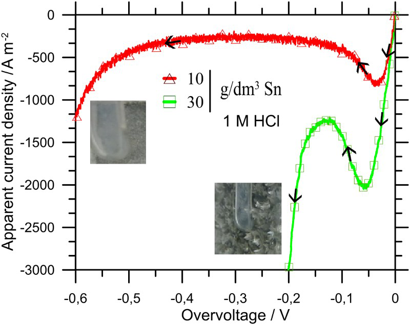
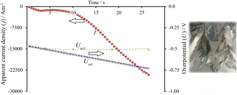
Figure 9 gives a clear example for the case when the potentiostat – applying relatively long steps of polarization – was unable to follow the potential program and the actual potentials (Uact.) lagged behind the set values (Uset) because the actual cathode surface area was growing considerably. The fast and loosely growing crystals combined with the high tin concentrations at their tips and edges allowed the current – or the apparent current density (j) – to increase without actually increasing the real current density at virtually unchanged potentials. If the effects of increased tin concentration and vigorous agitation are combined, as examined by Toth et al. (2014), not even a short range of limiting current can be seen. However, in this case, the current does not reach higher values than in the stationary solution, because the crystals are growing less far out from the surface, as deposition takes place also at the roots of the dendrites. However, the deposit is still looser than that grown in agitated solutions of low tin concentration.
Although it is practical to apply the lowest safe acidity, the effect of increased HCl concentration on the cathodic process was also investigated by the potendiodynamic technique. The diagrams of Fig. 10 obtained with 1 and 2 M HCl solutions, respectively, do not deviate significantly. Thus, the HCl concentration can be regarded as little affecting the cathodic deposition in the examined range, although with the increased HCl concentration the same overpotential can generate slightly higher apparent current. This may be in correlation with the slightly rougher crystal structure also seen in Fig. 10b.
Potentiodynamic deposition in stationary solutions of 30 g dm−3 Sn (15 s run with 5 mV/0.5 s steps), a 1 M HCl; b 2 M HCl concentration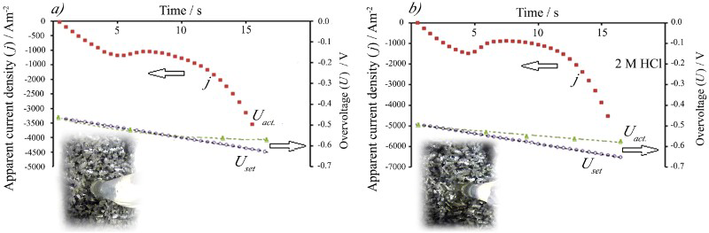
Suitable conditions for industrial production of tin by electrorefining require a dense and homogeneous distribution of relatively short and densely packed crystals at the cathode surface. Such performance was best approximated by the 5–10 g dm−3 Sn–1 M HCl vigorously agitated solution. These conditions are illustrated with the chrono-potentiometric curves and the photograph obtained by an extended potentiodynamic run in Fig. 11. Agitation of the solution by magnetic stirring can be easily executed in the experimental cell; however, it would be difficult in commercial practice. Industrial cells usually apply forced circulation of the solution; however, its effect is rather limited, except for maintaining the conditions of the electrolyte.
Potentiodynamic deposition in agitated (500 rev min−1) 1 M HCl solution of 5 g dm−3 Sn concentration (30 s run with 5 mV/0.5 s steps)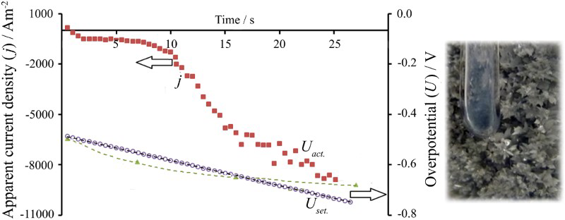
Long-term refining experiments
Analysis of the products obtained from a tin–silver anode material by applying suitable electrolysis conditions (20 g dm−3 Sn, 1 M HCl, 1000 A m−2) in a conventional cell
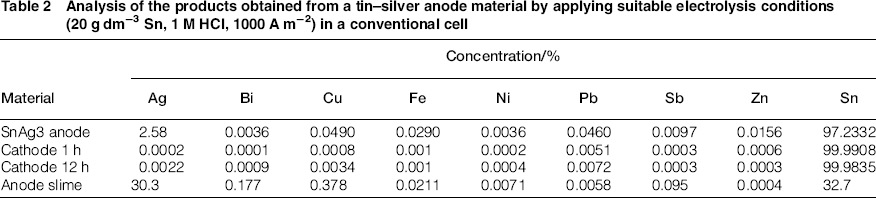
It can be seen that the produced tin was extremely pure. The degree of purification decreases only slightly with the elapsed time, even without any conditioning of the electrolyte. All the practically important impurities, even those of low original concentration – like copper – in the raw material were removed by the long-term procedure. The practically perfect separation of silver may offer a possibility of its selective recovery. The overall purity of the obtained cathode can be estimated as approximately 99.99 wt-%, which is unusually high at the market. This metal, recycled from the soldering scrap, can be used advantageously for the dilution of the soldering baths, or for other applications of high demand for purity.
The other product of the electrorefining procedure is the slime layer collected at the surface of the anode. After the appropriate high-temperature fusion and digestion procedure, it was also analysed by ICP-AES. Table 2 also shows that silver, as a significantly nobler element, reports almost entirely to the anode slime. The composition of the anode slime confirms the efficient separation of also copper, the main impurity, picked up from the structure of the electronic devices soldered. The slime layer collected from the anode surface is a valuable byproduct, which can be used as a raw material for extracting silver and other values.
Conclusions
The specially designed system allowing the in situ measurement and continuous recording of the changing electrode mass showed that the usual levels of alloying in the modern tin-based lead-free soldering materials do not disturb the anodic dissolution of tin significantly. Applying higher anodic current densities than 1000 A m−2 causes higher anode potentials than the Sn(IV)/Sn(II) redox potential in the HCl solution, thus it may result in the generation of Sn(IV) species. Conclusions drawn from the thermodynamic simulation were confirmed by in situ electrode mass measurement results, pointing out feasible reactions of Sn(IV) species with the anode and also the cathode tin. During a longer electrolysis run, the thick anode slime layer may hinder the tin ion transport, therefore, the anode potential and thus the generation of Sn(IV) species may be increased. However, the small metallic particles in the anode slime layer are suitable to reduce the Sn(IV) ions efficiently to the preferred divalent state. Thus, an optimum thickness of a loose anode slime layer may be beneficial for the gross production of Sn(II) ions in the complex anodic reaction.
With initial cathodic current densities higher than 500 A m−2 the hydrogen evolution is noticeable. Hydrogen bubbles attached to the surface may also contribute to irregular electrocrystallisation. The potentiodynamic investigations have pointed out the inherently fast charge transfer and the slow transport of the tin species, leading to the rough dendritic morphology of the cathodic deposit. Stationary solutions of 5 g dm−3 Sn concentration allow only a low limiting current density at the cathode. In solutions of ∼30 g dm−3 Sn concentration, however, the limiting current regime is quickly skipped and the deposited crystals are growing beyond control. Deposit morphology was found best in solutions of low Sn concentration (∼5 g dm−3) with vigorous agitation, enhancing the ion transport to the active surface. The concentration of HCl in the examined 1–2 mol dm−3 range had little effect on the electrode processes. The purity of the refined tin can reach 99.99%. Silver and copper are efficiently removed to the anode slime which may be regarded as a valuable byproduct.
Footnotes
Acknowledgement
The research work presented in this paper is based on the results achieved in the Center of Applied Materials Science and Nano-Technology at the University of Miskolc and within the TÁMOP-4.2.2.A-11/1/KONV-2012-0019 project, and carried out as part of the TÁMOP-4.2.2.D-15/1/KONV-2015-0017 project in the framework of the New Széchenyi Plan. The realisation of this project is supported by the European Union and co-financed by the European Social Fund. This paper was originally presented at the 2014 Sustainable Industrial Processing Summit / Shechtman International Symposium and has subsequently been revised and extended before consideration by Mineral Processing and Extractive Metallurgy.