
Abstract
The content of the review covers, first, generalities on creep. Then, the creep of ceramics and fibres, that are key constituents of fibre-reinforced ceramic matrix composites (CMCs) are addressed. The general features of ceramic matrix composites that may influence the creep behaviour and creep rupture are discussed. Emphasis is placed on microstructure–property relationships and load sharing between fibres and matrix that are critical for CMCs. Then, creep tests and the creep behaviour of various types of fibre-reinforced composites are presented. Mechanisms and models are discussed. The influence of various factors including composite structure, constituent properties (matrix and fibres), interfacial properties and environmental conditions are examined. The paper focuses on non-oxide composites like SiC/SiC that received much attention during the last three decades. Creep of oxide ceramics, fibres and composites are addressed more briefly.
Introduction
A continuous fibre-reinforced ceramic is a structure constructed of several parts: the reinforcing fibres, the matrix and the fibre/matrix interfaces. Unlike monolithic ceramics, the mechanical behaviour results from the synergetic response of the constituents to loads. It is governed by the respective properties, arrangement and volume of constituents. This functioning is disturbed by stress-induced damage and environment aggressions.
There is a wide variety of fibre and matrix types, so that a variety of composite materials can be produced. The following combinations emerged as potential candidates for industrial applications at high temperatures: the oxide fibre-reinforced oxide matrices (referred to as oxide/oxide composites), and the non-oxide fibre-reinforced non-oxide matrices (referred to as non-oxide composites). The most significant effort was put on SiC/SiC composites because they appeared the first as candidates for use in industrial systems at high temperature. The oxide/oxide composites were penalized by high sensitivity to creep. Various manufacturing processes are available for a given combination of fibre and matrix, so that the produced composites may present differences that are not reported in the literature, although they may influence the composite behaviour. Additionally, different brands of fibres having the same composition but different mechanical properties are available so that it is difficult to refer to a generic system. For instance, a SiC/SiC composite may be reinforced with about 10 different SiC fibre-types, whereas the matrix may be generated via about more than 7 different processes. These composites were essentially manufactured by industry. The exact composition of composites is not indicated by authors, so that results reported in the literature for the same type of composite may look contradictory, and the behaviour cannot be discussed with respect to microstructure nor composition.
The design of CMC components for high-temperature applications must consider creep so that excessive strain or premature failure is avoided during the anticipated lifetime of the structure [3]. In contrast to ceramics, there are relatively few published reports about the creep of CMCs, although they are being developed for use in high-temperature structural applications. A certain amount of test results has been reported on the creep rate of CMCs under various conditions of temperature, environment and stress, and models and mechanisms have been proposed. Knowledge has been produced in the last decade on microstructure–property relationships for CMCs. But no review of existing literature on creep has been published.
Most of the papers on creep of fibre-reinforced ceramic matrix composites were published in the 1990–2000 years. There are two families of approaches to the creep of fibre-reinforced composites: - the macroscopic approaches that consider the composite as a bulk material. These approaches were inspired by creep studies on monolithic ceramics. They use the concepts and the equations at composite macroscopic length scale. - the micro–macro approaches that consider the creep behaviour of constituents. A certain effort was put on the creep behaviour of fibres, whereas less attention was devoted to the matrices. However, a large amount of creep results were obtained on monolithic ceramics, which may be useful for the behaviour of matrices. Models of creep behaviour have been proposed that establish the relations with constituent behaviour.
The paper addresses extensively the creep behaviour and fracture of non-oxide composites like SiC/SiC that received most attention during the last three decades. Results on oxide ceramics, fibres and composites are also reported. Carbon fibres and Carbon/Carbon composites that creep at much higher temperatures were not discussed for reasons of paper length. The review recapitulates first the creep behaviour of monolithic ceramics and fibres. The knowledge produced in the literature on the creep of monolithic ceramics proposes a reference approach for the investigation of creep behaviour of materials. It is useful for the understanding of microscopic features of the creep behaviour of CMCs. The fibres are a key constituent that governs the mechanical behaviour and fracture of CMCs. Emphasis is placed on the microstructure–property relationships and load sharing between fibres and matrix. The general features of stress-induced damage of ceramic matrix composites that influence the creep behaviour and rupture are discussed. Then, creep tests and the creep behaviour of various types of fibre-reinforced composites are presented. Mechanisms and models of composite creep are discussed. The influence of various factors including composite structure, constituent properties (matrix and fibres), interface properties and environmental conditions are examined.
Generalities
Creep refers to time-dependent permanent deformation activated by long exposure to heat under the influence of mechanical stresses. Irreversible deformations result from temperature-dependent microstructural changes. When the material undergoes a time-dependent elongation that cannot be tolerated while in service, the attention is mostly focussed on the rate of deformation (creep rate). Creep rate laws are derived from the time-dependent deformation curves determined during tests under constant load. However, creep may lead to fracture. The determination or prediction of time to failure under stress is thus required when dimensional changes are acceptable, but rupture cannot be tolerated.
The effects of creep deformation generally become noticeable at temperatures greater than about 35% of the absolute melting point for metals and greater than about 45% of the absolute melting point for ceramics [1]. Creep testing generally refers to experimental conditions of constant stress or load in compression, tension or bending at high temperature in the inert atmosphere. Tests at constant strain rate were also conducted. They are easier and quicker to perform, but detailed creep study require tests at constant load or stress. Stress rupture tests place emphasis on time to failure at stress and temperature.
Creep of monolithic ceramics
Creep curves
The creep curves consist of a plot of strain as a function of time. Typical three-stage curves are usually observed under a condition of constant load that comprise (Figure 1): - an instantaneous strain, - an initial nonlinear domain corresponding to primary stage of creep (stage I) - a linear domain corresponding to steady-state or secondary stage (stage II) - and a nonlinear domain with an upward curvature or tertiary stage (stage III) to the point of fracture. Schematic illustrations of the creep curves obtained from tests conducted under condition of constant load (a) and constant strain rate (b).
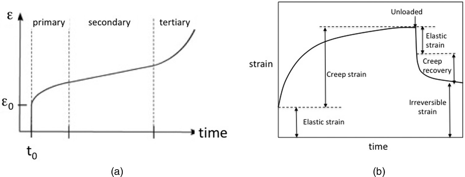
Many creep tests in compression on ceramics under conditions of constant load have failed to reveal the tertiary stage, and the tests have been discontinued within stage II [2]. However the three-stage behaviour has been observed in compressive creep tests conducted on polycrystalline MgO, Y2O3 stabilized ZrO2 and in tensile creep tests on single crystal and polycrystalline alumina [2]. The total strain occurring during the primary stage of creep of polycrystalline ceramic is often fairly small [2]. The secondary stage often extends over a long range of strain and ultimately leads to tertiary creep and fracture [2]. The comparison of creep curves obtained under comparable conditions of stress and temperature shows that SiC exhibits smaller creep strains than Si-based ceramics, and oxide ceramics exhibits the larger deformations. The presence of sintering aids affects the creep resistance. No material strength loss is observed during the first two stages of creep.
Creep behaviour under constant strain rate is described by a nonlinear stress–strain curve (Figure 1(b)). When the load is removed, Figure 1(b) distinguishes the elastic deformation (instantaneous elastic recovery), the time-dependent nonpermanent deformation during primary creep (creep recovery) and the permanent deformation during secondary creep. It is difficult to correlate directly the curves for constant stress and constant strain rate.
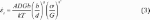
The creep deformation is dependent on three main parameters: the applied stress, time, and temperature. Depending on the material data, this dependence can be expressed by the following product of functions:
 where εc
is the creep strain, σ is the applied stress, and T is the absolute temperature.
where εc
is the creep strain, σ is the applied stress, and T is the absolute temperature.
Expressions for the functions f, g and h have been proposed by a large number of researchers. The most common forms for the stress, time and temperature functions are given in [3]. Note that for ceramics and fibres, power laws for f(σ) and g(t) and exponential law for h(T) are commonly used. The functions fit empirically the test data.
The use of a separate function for stress is generally restricted to the secondary creep region of the creep curves. The separation of time and temperature is not as commonly observed as the stress; and generally researchers tend to combine the two effects into one parameter (Larson Miller parameter).
Primary creep
In the primary stage, the creep rate decreases with time to a minimum (Figure 1(a)). The deformation mode is essentially visco-elastic. All the accumulated strain can be recovered during unloading: creep recovery (Figure 1(b)). The strain rate is in inverse proportion to time. Various expressions for creep rate under constant stress and temperature can be derived from the expressions of proposed time functions as indicated above. The following equation is often used [4–6]:

where t is time, Cp is a constant, p′ is time exponent.
Secondary creep
In the second stage, the strain rate is constant (Figure 1(a)). The creep deformation is governed by diffusion. The steady-state creep is the most understood. For most mechanisms of high-temperature creep, steady-state creep rate follows the following expression [7]:
where 
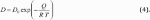
where D 0 is a frequency factor, Q is the activation energy for the diffusion process and R is the gas constant (8.31 J mol−1 K−1).
Each creep mechanism is uniquely specified by the values of the constants A, q, n′ and by the activation energy. Values for the creep mechanism characteristics n, p, and Q obtained in tests on polycrystals are reported in [7]. Laboratory creep tests are conducted to estimate the creep characteristics and infer the precise deformation mechanism.
Many theoretical mechanisms have been proposed for the secondary creep. They are broadly divided into two distinct groups: grain boundary mechanisms and lattice mechanisms.
The lattice mechanisms are intragranular in nature. They are based on the intergranular motion of dislocations or the flow of vacancies through the grains (this process is known as Nabarro–Herring creep [2,7]). They are equally likely to be observed in single crystals and polycrystalline ceramics.
The boundary mechanisms are observed in the creep of polycrystalline ceramics. Grain movement is either associated (Lifshitz sliding [7,8]) or not associated (Rachlinger sliding [7,9]) to elongation of the grains.
Lifshitz sliding is accommodated by the diffusional flow of vacancies. This process is known generally as ‘diffusional creep’. The flow of vacancies takes place along the grain boundaries (small grain size) (Coble creep [7,10]) or through the grains (large grain size) (Nabarro-Herring creep [7,11,12]).
Rachlinger sliding arises in those ceramics where a glassy phase is present at the boundary [7,13]. In the absence of a glassy phase, sliding may be accommodated locally by the formation of grain boundary cavities [7,14] or by the formation of short folds at the triple points [7,15].
Tertiary creep
In the third stage (Figure 1(a)), the creep deformation is governed by cavitation. In the tertiary stage, necking phenomena or internal voiding decreases the effective area of the specimen. The plot of steady-state creep rate against time to rupture is generally fitted by the Monkman–Grant law of creep rupture [16]:

where tf
is creep rupture time, 
The Larson–Miller parameter combines temperature and logarithm of time to describe the equivalence of time at temperature for a steel under the thermally activated creep process of stress rupture [17]. It is used to predict the stress and time for long lives on the basis of much shorter data. It permits the calculation of the equivalent times necessary for stress rupture to occur at different temperatures. It has the general form:
 where LM is the Larson–Miller parameter, T is the temperature in degrees Rankine (°F + 460) or Kelvin; tf
is the rupture time in hours for an isothermal condition.
where LM is the Larson–Miller parameter, T is the temperature in degrees Rankine (°F + 460) or Kelvin; tf
is the rupture time in hours for an isothermal condition.
Mechanisms of creep in ceramics
The total strain occurring during the primary stage of creep of polycrystalline ceramics is often fairly small [2]. It is considered that the secondary stage warrants more attention since it often extends over a long range of strain and ultimately leads to fracture [2]. Very numerous studies of creep have focussed on plastic deformation.
A review of creep behaviour of stoichiometric CVD SiC [18] has reported that primary creep of CVD SiC occurs immediately upon loading and tends to saturate with time. In severe conditions, primary creep strain in the CVD SiC can reach as high as 1%. The primary creep strain–time curve was found to fit the following relationship for the conditions of stress and temperature employed [19]: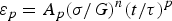
where Ap , n, p, and τ are creep parameters, t is time. For the loading orientation of 45° from the CVD growth axis, these parameters are n = 1.63, Ap = 29, p = 0.081, and τ = 0.0095 s for the temperature of 1923°K, G is shear modulus.
Since the five independent slip systems necessary for general dislocation deformation are not available in typical polycrystalline ceramics, the plastic steady-state deformation creep behaviour is dominated by diffusional processes.
Various types of additives are used to promote densification. After sintering, glassy or partially crystallized phases are present at grain boundaries. Sintered ceramics like silicon nitride contain glassy or partially crystallised secondary phase at grain boundaries, where it forms a thin glassy film [20]. The secondary phase affects the deformation in three ways: it may act as a lubricant (viscous flow creep), improve material diffusion (solution–precipitation creep), it provides the location for the nucleation and growth of cavities during the deformation process (creep by cavitation).
In most cases, the minimum strain rate reached in the steady-state stage is characterized by the classical power-like creep Equation (3). The rate-controlling creep mechanism in a polycrystal is usually determined by reference to the experimental values of creep parameters n, p and Q. The attribution of the experimental creep parameters to deformation mechanisms requires an accompanying description of the microstructural dynamical evolution. The influence of some microstructural features capable of accompanying creep has been analysed in [20], a review dedicated to silicon nitride ceramics. Let us mention dynamic grain growth, and microstructural damage induced by creep. In particular, that latter mechanism was found to be the cause of exponent n increase [20].
In tensile creep, the stress exponent has been shown to increase with increasing applied stress. The classical equation was considered to be not suitable under tension. Alternative equations have been proposed [20]. This influence of stress on n was also attributed to the stress sensivity of creep cavity nucleation rate [20]. Asymmetry between tensile and compressive creep was found in various ceramics including SiC-based [20], Al2O3-based ceramics [20], as well as in other materials with significant amounts of glassy phases [20]. Thus, under similar conditions of applied stress and temperature, these ceramics are systematically and significantly less creep resistant under tension than under compression. This asymetry is attributed in [20] to the formation of cavities during tensile creep that contributes only to the axial strain, and they provide a negligible contribution to the compressive strains.
In polycrystalline SiC ceramics, n = 1 and creep results from diffusional processes either at grain boundaries (Coble creep, p = 3) or within grains (Nabarro Herring creep p = 2). A high activation energy corresponds to Nabarro Herring creep. The creep rate is very sensitive to grain size: p = 2 or 3. Identical trends have been reported for both α- and β-SiC.
Diffusional creep in polycrystalline SiC occurs by diffusion of carbon [21] or silicon [22] at grain boundaries or within grains [23] or by diffusion of impurities at grain boundaries [24]. Activation energies for diffusion of carbon and silicium within grains in β-SiC made via chemical vapour deposition have been estimated to be 840 [25] and 910 kJ mol−1 [26], respectively. It is worth keeping in mind that creep of polycrystalline SiC cannot be controlled by dislocation motions at temperatures <1700°C.
Steady-state creep rates for polycrystalline CVD SiC have been measured under compressive stresses only, at temperatures above ∼1673 K, when the stress axis is 45° inclined from the deposition direction; temperatures as high as 2023 K were required when the stress axis was parallel to the deposition direction [18]. The strain rate was found to follow the power-law creep equation [19]:
 where As
= 2.0 × 10³, n′ = 2.3, Q = 174kJ mol−1 (activation energy).
where As
= 2.0 × 10³, n′ = 2.3, Q = 174kJ mol−1 (activation energy).
Below 1923 K the controlling creep mechanism is dislocation glide. Overcoming of the Peierls stress is believed to be the rate controlling process for this mechanism with a relatively low activation energy (approximately more than one-fourth that for self-diffusion of Si in α- or β-SiC) [18].
The important role played by cavitation in the high-temperature fracture process in structural ceramics is widely recognized [27–30]. Failure often occurs through the gradual growth and coalescence of cavities by diffusive processes, until a macrocrack is formed that subsequently propagates to failure. The process is inhomogeneous, involving preferential cavitation in certain regions of the polycrystalline array [30,31]. Evans and Rana developed a life-prediction model (extended by Suresh and Brockenbrough [32]) in which the strain results from the elastic opening of facet-sized microcracks.
Mechanical behaviour of composites
Fibre-reinforced ceramic matrix composites
The composites capable of the highest mechanical performances possess continuous fibre reinforcement. They are the subject of this paper. They are of great interest for thermostructural applications.
Definition of notations for matrix identification.
Characteristics of the main composite systems discussed in this paper. Note the order of symbols used to denote composite: the fibre type is indicated first.
Most fibrous oxide–oxide composites have large matrix void volume (30–50%) [40,41]. Oxide–oxide composites containing interface coatings are still in the research stage, while porous matrix materials without fibre coating are currently more advanced [40]. The porous oxide matrices are very compliant and very weak compared to the fibres. The composite stiffness and strength in fibre direction are nearly those of the fibres [40].
The oxide fibres [42] that are commercially available are mostly based on alumina-based ceramics. They display high values for tensile strength and Young’s modulus, and diameter as fine as 10–12 μm (Table 2). The Nextel oxide fibres are the most widely used reinforcements for continuous fibre oxide–oxide composites [40,41,43].
The non-oxide composites exhibit superior tensile strength and creep resistance to the oxides. Lower creep rates are observed at temperatures >1200°C, even under high stresses, whereas the oxide fibres can barely exceed 1000°C [44–51]. They are used in various 2D or 3D forms.
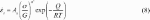
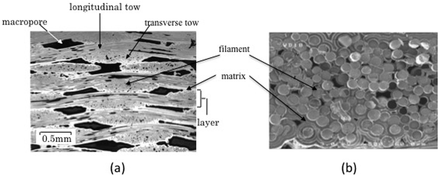
The fibre-reinforced composites are highly heterogeneous and versatile materials as the result of the presence of fibres, matrix, fibre/matrix interfaces/interphases and flaws. Moreover, several entities at micro- and mesoscopic length scales can be defined depending on fibre architecture: single filament–interface–matrix assembly that represents a fundamental entity of composite (Figure 2(b)) [52]. It is referred to as microcomposite. It can be manufactured as test specimen (Figure 3). single tow-reinforced matrix in woven composites (Figure 2(a)), referred to as minicomposite [53–55] that can be manufactured as test specimen (Figure 3). unidirectional or woven plies in laminated composites. Cross-section of a 2D woven SiC/SiC CVI composite specimen (a). Micrograph of part of the section of a matrix infiltrated tow in woven composite is also shown (b). The SiC tows comprise 500 continuous parallel SiC filaments. Note that the fibres are closely spaced due to textile manufacturing. Typical microcomposite (a) and minicomposite (b) testspecimens fractured under conditions of uniaxial tension parallel to fibre axis.
Furthermore, the woven CVI SiC/SiC contains: large pores (referred to as macropores) located between the plies or at tow cross over regions within the plies and (iii) a uniform layer of matrix over the fibre preform (referred to as the intertow matrix) (Figure 2(a)). Much smaller pores are also present within the tows (Figure 2(b)). Pre-existing cracks are present in the matrix of SiC/SiC composites made via PIP process [56].
Mechanical behaviour under tensile loading
Fibre-reinforced CMCs are elastic damageable materials, which mean that they have an elastic response even in the presence of damage. The shape of the stress–strain curve depends strongly on the respective deformations of the fibres oriented in the loading direction and of the matrix.
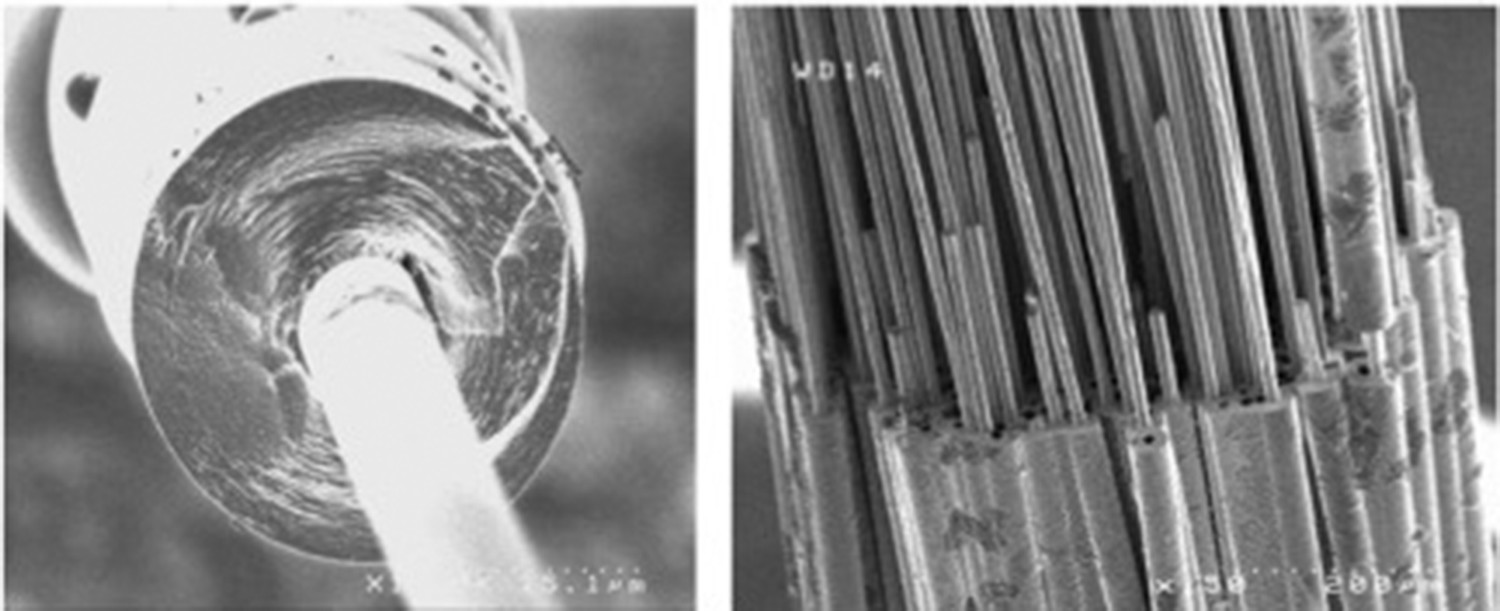
A nonlinear stress–strain curve (Figure 4) reflects damage sensitive behaviour. It is obtained when matrix stiffness contributes significantly to composite Young’s modulus, as shown by the mixtures law [57]: Typical tensile stress–strain behaviors measured on 2D woven Nicalon SiC/SiC composites: (a) strengthened fibre/matrix interfaces, and (b) weak fibre/matrix interfaces [52].

where Ec , Em and Ef are elastic moduli of composite, matrix and fibres, respectively, Vm and Vf are volume fractions of matrix and fibres.
As Em degrades as a result of transverse cracking in the matrix, Ec decreases. The stress–strain curves display nonlinearity (Figure 4). In SiC/SiC and C/SiC composites, the matrix is stiffer than the fibres: Em (∼410 GPa) > Ef (200–400 GPa). It carries initially a substantial part of the load. As matrix damage proceeds the load is transferred progressively to the fibres.
A linear stress–strain curve reflects damage insensitive behaviour. It is obtained when initially Em
<< Ef
. As shown by the resulting Equation (10), composite Young’s modulus is commensurate with fibre stiffness:
The stresses operating on the matrix are low so that cracking is limited or nil. In those composites with a compliant matrix compared to the fibres (Em < Ef ), the tensile behaviour is dominated by the fibres. These composites display no or mild deviation from linearity when loaded along one of the reinforcement axes. Oxide –oxide composites contain an exceptionally weak porous matrix [58]. In PIP/SiC composites, the matrix may be compliant as a result of heavy microcracking due to crystallization and shrinkage processes of the multiple polymer pyrolysis and densification steps during fabrication [56].
In those damage-sensitive unidirectional composites under on-axis tensile loads, diffuse cracking is the basic damage phenomenon: it consists of multiple through-the-thickness cracks that form in the matrix, perpendicular to fibre direction and that are deflected at fibre/matrix interfaces. Crack density increases with the applied load.
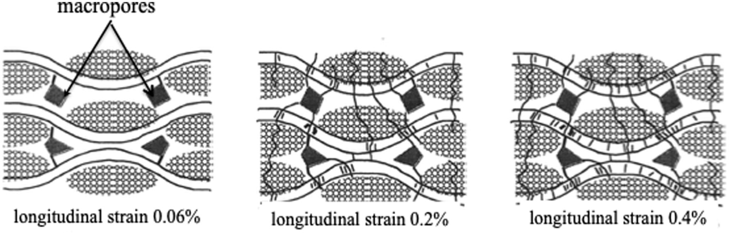
In the composites reinforced with fabrics of fibre bundles, diffuse matrix cracking takes place at various length scales depending on the architecture [57,59]. A big effort combining experimental and modelling work was put on the microstructure/behaviour relationships for 2D woven CVI SiC matrix composites. The damage mode of 2D woven CVI SiC matrix composites has been identified using in situ microscopy during tensile tests and analysis of acoustic emission signals [57,59]. It was shown that the damage phenomenon is a top down process from larger (material between the longitudinal tows) to smaller (matrix within the longitudinal tows) volumes of material, according to scale effect on the fracture stress [54]. In 2D woven SiC/SiC and C/SiC, matrix damage consists of through-the-thickness transverse cracks located, in a first step, between the longitudinal tows and deflected by the tows, in a second step, within the longitudinal tows and deflected by the filaments (Figures 5 and 6) [52,57,59]. The damage kinetics as the load increases is shown in Figure 6. Micrograph showing typical transverse matrix cracks in 2D woven SiC/SiC composite (made via CVI) that appeared under increasing load: first in the interplay matrix, second through the transverse tow (perpendicular to loading direction), third through the longitudinal tow in loading direction. Sequence of multiple cracking under increasing uniaxial tensile load observed in a 2D woven SiC/SiC composite (schematic diagram) (a) cracks initiated from macropores and propagated in the interply matrix (strains between 0.025% and 0.12%), (b) through-the-thickness cracks initiated at fibre/matrix interface in the transverse tows (strains between 0.12% and 0.2%), (c) multiple microcracks created in the longitudinal tows (strains > 0.2%) [52,59].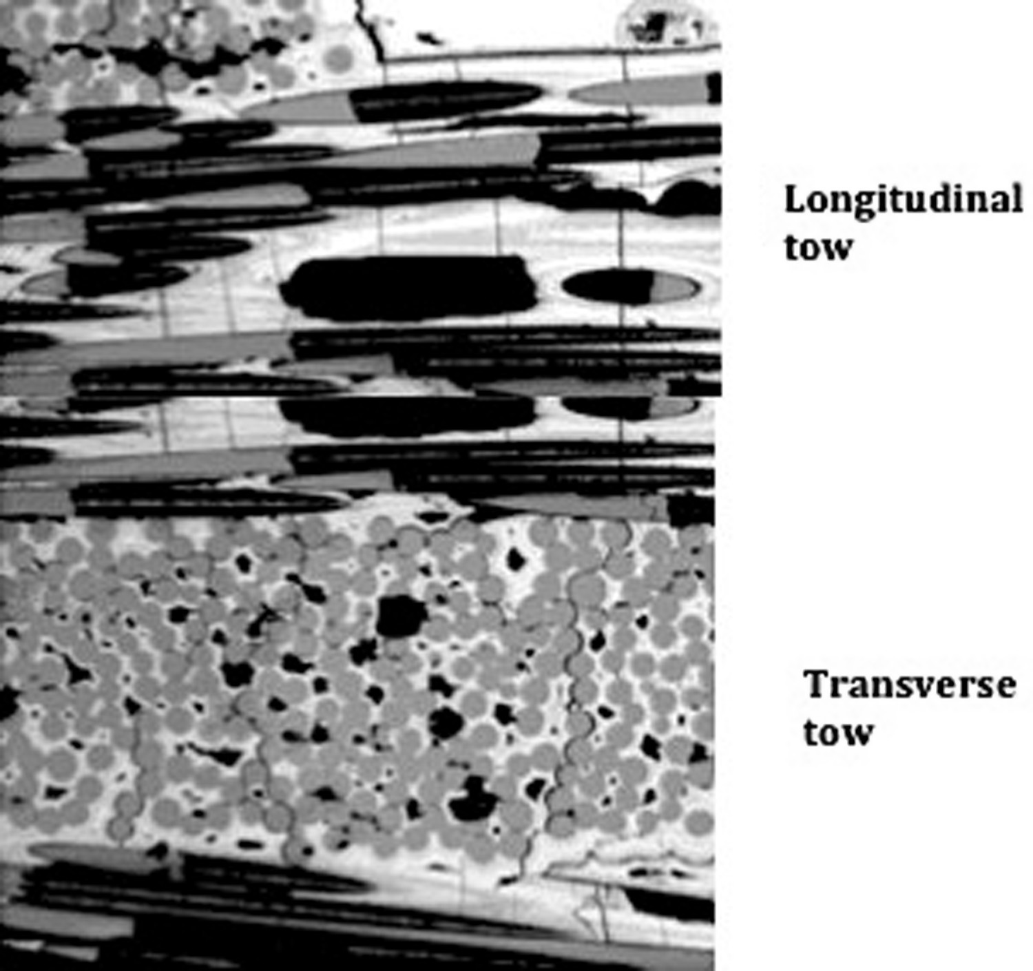
Elastic modulus loss as the load increases reflects the progress of load sharing: the first family of cracks (at strain = 0.2%) causes a 70% load drop in the 2D woven SiC/SiC. The load becomes carried essentially by the longitudinal minicomposites (tow reloading) in the debonded parts. Then, microcracks within the longitudinal tows are responsible for a subsequent 10% loss [33,60]. Load sharing is affected further, and the load becomes carried essentially by the debonded portions of filaments (fibre reloading). SiC filaments and then tows fracture at strains > 0.7%.
Morscher [53] compared the matrix cracking behaviour under tensile loading along a fibre direction for melt-infiltrated SiC matrix composites consisting of Sylramic-iBN fibres with a wide variety of fibre architectures, including 2D woven, braided, 3D orthogonal, and angle interlock architectures. As above with the CVI matrix composites, fibres are closely spaced due to textile manufacturing. Results highlight key features of matrix cracking that agree with the above architecture-dependent damage mode for 2D woven CVI SiC/SiC. Thus, matrix damage results from the multiplication of cracks as the load increases. The matrix cracks were observed to traverse through-the-thickness of the specimen. Then, the minicomposites were recognized as significant entities for matrix damage. The tow minicomposites perpendicular to load direction that constitute the largest region were found to be the weakest region for onset of through-thickness matrix cracking, according to scale effect on the fracture mentioned above. However, the improved densification of MI composites gives improved matrix resistance to cracking at lower stresses since most of the macropores are filled by Si. This could prevent the first family of cracks observed on CVI SiC composites from initiating at cross over points in the woven structure [61].
A different scenario of damage has been inferred from the investigation of the tensile properties of a 0°/90 Schematic of pattern of matrix cracks in cross-ply (0°/90°)4s Nicalon SiC/CAS composite [62]. Arrows shows the directions of crack growth.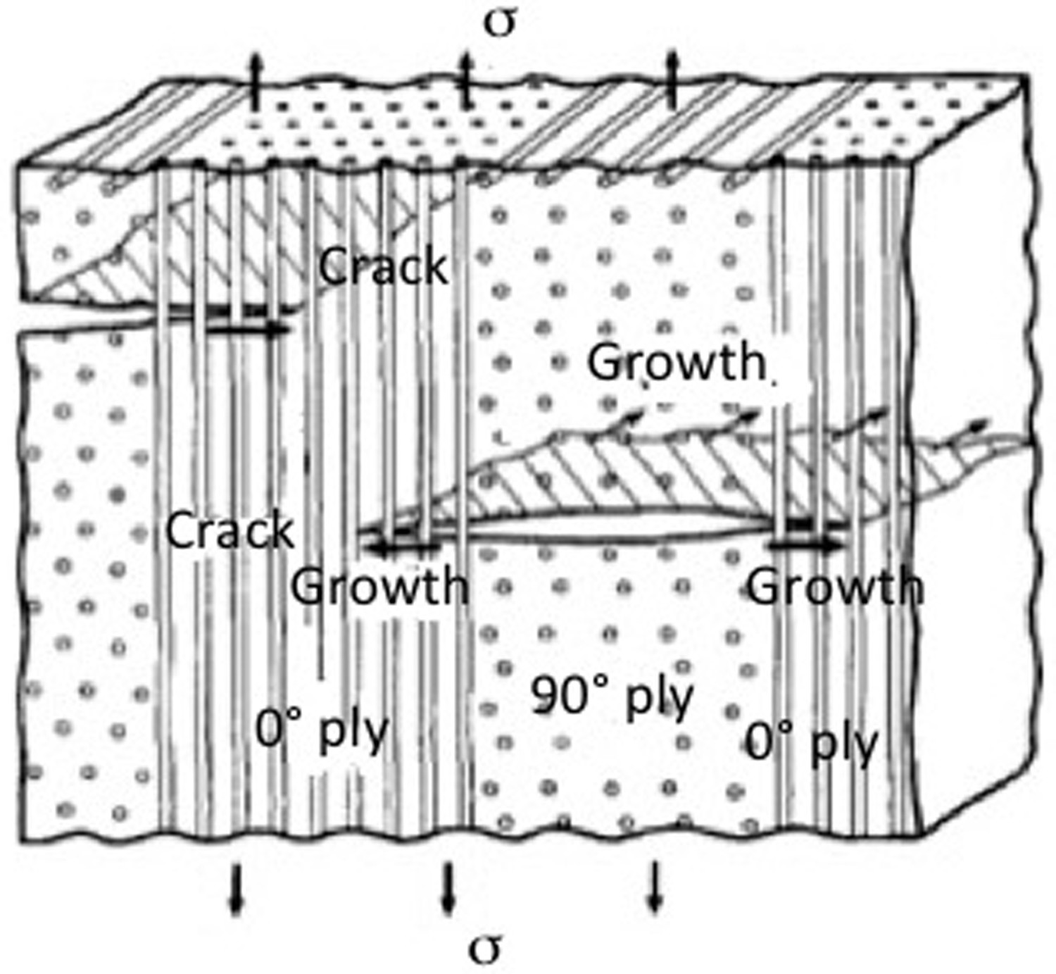
Matrix damage can play a significant role during creep. The crack pattern that depends on the applied stress and on the structure is in place before creep. During creep under constant load, fibre deformation in debonded areas may be expected to govern the creep behaviour, whereas multiplication of matrix cracks may not take place further. This trend is illustrated by several results in the literature reported in this paper (see for instance 34,56,63). Precise description of matrix damage at pertinent length scales is thus required for modelling creep of composites.
Creep of ceramic fibres
Creep behaviour
Non oxide fibres
The first generation of Nicalon fibres contain SiC (49 mol-%), important quantities of free carbon (28 mol-%) and an amorphous silicon oxycarbide (Si–C–O) phase (23 mol-%) resulting from the incomplete pyrolysis of the oxygen-cured fibre [48,64,65]. At high temperatures (>1200°C), the Si–C–O phase decomposes, forming SiC and gaseous species such as CO and SiO whose diffusion through the fibre and reaction with the free carbon are believed to create pores and other defects in the fibre structure [66]. Such a decomposition causes strength and Young’s modulus degradations and affects the fibre creep behaviour even in inert atmospheres [48,66–69].
Nicalon fibres tested in argon and in the air were found to exhibit only primary creep at temperatures in the range 1200–1400°C [48,67], as a result of fibre decomposition.
In CO and CO/argon gas environments, the Si–C–O phase is stable, and the creep cuves display a long steady-state domain in addition to the primary creep region [67]. Primary creep curves were fitted by a logarithmic strain-time relationship [67,68]. It was assumed by authors that the minimum strain rate reached in the steady-state stage is characterized by the classical power-like creep Equation (3). The stress exponent n′ ≈ 1 was estimated, the measured activation energy (≈450 kJ mol−1) was found to be consistent with the activation energies of thermally activated viscous flow of glasses at high temperatures [40].
The subsequent generations of SiC fibres were free of Si–C–O amorphous phase. They include the second generation of low oxygen type fibres such as Hi-Nicalon from NGS Advanced Fibres, and the third generation of near-stoichiometric fibres like Sylramic from Dow Corning, Hi-Nicalon S from NGS Advanced Fibres and Tyranno SA from UBE. They display improved creep properties and higher thermal stability when compared to the first-generation fibre [48]. Hi Nicalon fibres were found stable up to 1600°C [48], Hi Nicalon S fibres up to 1400°C, and Sylramic and Sylramic-iBN fibres up to 1800°C after exposure in argon for 1 h [70]. Beyond these temperatures crystallisation and grain growth take place. These temperature limits decrease with increasing time exposure [70].
Hi-Nicalon fibres creep tested in air and in argon at temperatures >1200°C [48] displayed a long steady-state domain. No tertiary creep was observed. Stress exponents (Equation (3)) estimated from steady-state creep behaviour at various temperatures were in the range 1.96–3.04. This variability may reflect some effects of creep testing procedure, since the stress exponent was calculated from creep tests at various temperatures. The activation energies for creep of Hi-Nicalon fibres in argon (193–292 kJ mol−1) were smaller than those derived from experiments conducted in air (344–423 kJ mol−1) [48]. Due to the lack of data on steady-state creep in argon, this difference was not assessed [48]. Based on TEM-based description of fibre nanostructure, (the Hi Nicalon fibre can be regarded as a mixture of wrinkled carbon-layer packets and SiC grains [48]) and the values of stress exponent and apparent activation energies for creep, the proposed creep mechanism was SiC grain boundary sliding and dewrinkling and sliding of carbon crystallites [48].
The intrinsic creep behaviour of Hi Nicalon fibre and near-stoichoimetric fibres (third generation of SiC-based fibres) was determined from creep tests in secondary vacuum (residual pressure was about 10−4 Pa) [51]. Heating was generated by electric tension applied to the fibre. In such an environment, active oxidation is infinitively slow. The steady-state creep was observed after a more or less long primary creep stage, depending on the fibre (Figure 8): after about 140 h for Hi-Nicalon fibres at 1200°C, about 72 h for Tyranno SA3 (1) fibre at 1200°C, about 8 h for Tyranno SA3(2) fibre at 1250°C, and about 8 h for Hi-Nicalon S at 1650°C. The tests were interrupted before fracture after significant steady-state deformations: 300 h for Hi Nicalon and Hi Nicalon S and 60 h for both Tyranno SA3 fibres. Creep behavior of (a) Hi-Nicalon, (b) Tyranno SA3 (1), (c) SA3 (2), and (d) Hi-Nicalon S fibres [51].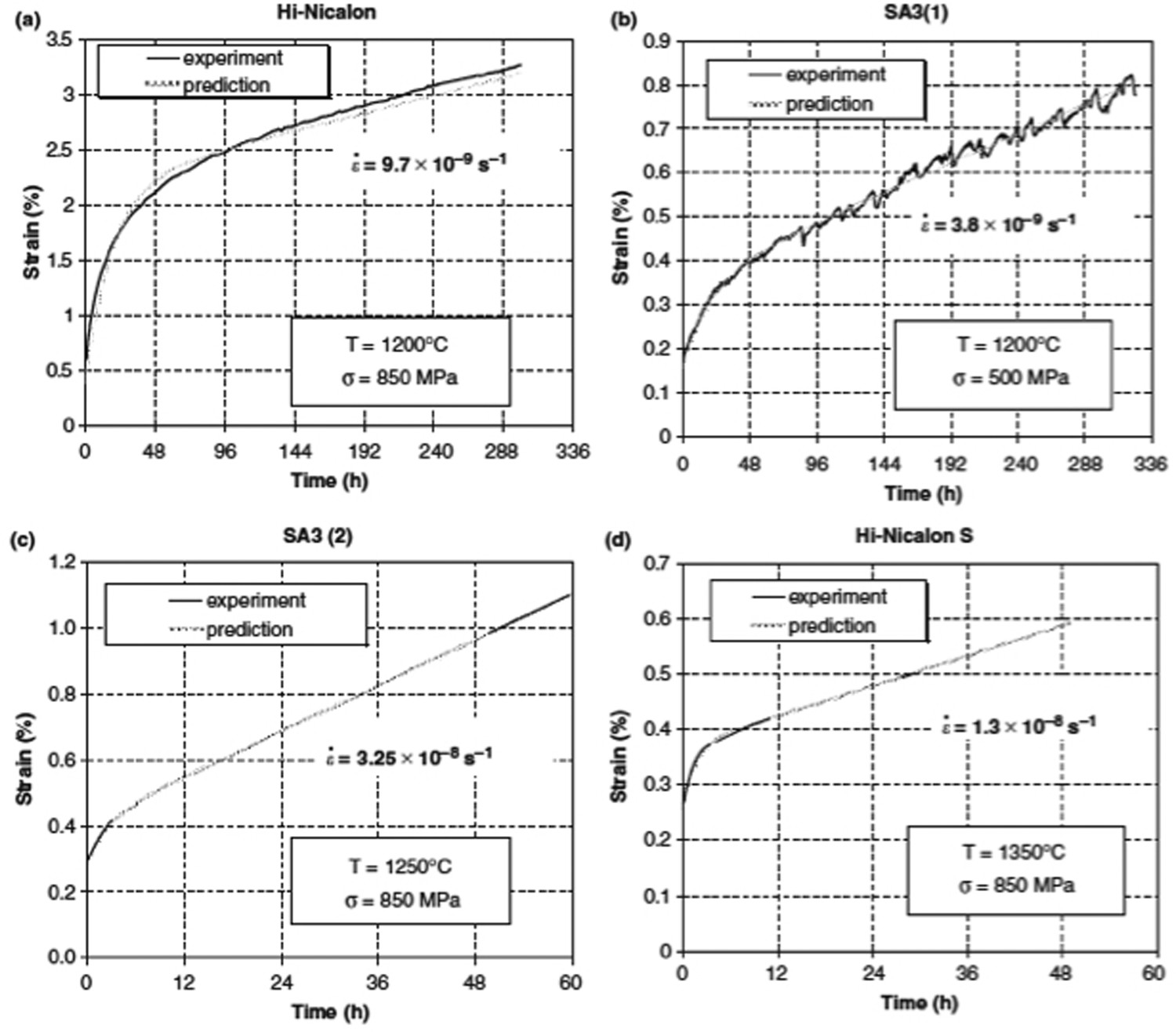
Primary creep can be attributed to viscoelastic deformation of carbon at grain boundaries. The viscoelasticity of carbon has been discussed by Kelly [71], and it has been observed by Sauder et al. [72] on various carbon fibres at high temperatures. The Maxwell equation of viscosity was found to fit properly the primary creep behaviour of these SiC-based fibres [51]:

where subscript p refers to primary creep, σ is the stress on the fibre, t is time, A = 2G and λ = G/η are constants; G is the shear modulus and η is viscosity.
The steady-state creep of Hi-Nicalon S and Tyranno SA3 fibres was characterized using Equation (3). Stress exponents n ≈ 2.5 were estimated for the Hi-Nicalon S and Tyranno SA3 fibres tested in vacuum [51]. For the Hi-Nicalon fibre, unsatisfactory fit of the creep curve by Equations (3) and (7) did not allow the estimation of stress exponent n. This effect was attributed to the growth of unstable low-density SiC phase [73] that starts at temperatres >1200°C in the Hi-Nicalon fibre, which causes a decrease in creep rate.
On the basis of values of stress exponent and apparent activation energy, the following mechanisms were proposed for secondary creep of Hi Nicalon S and Tyranno SA3 fibres: (1) Grain-boundary sliding without grain elongation and glassy phases (Rachinger type). Creep of polycrystalline SiC cannot be controlled by dislocation motions at temperatures <1700°C [26,74]. In polycrystalline ceramics, accommodation results from diffusion and fold formation at triple junctions. In SiC fibres, it probably involves deformation of turbostratic carbon grain boundaries [51]. (2) Diffusion of Al, C, or Si at grain boundaries in the SA3 fibre. The activation energy determined for SA3 fibres (370 kJ mol−1) [51] is close to that corresponding to diffusion of Al at grain boundaries in polycrystalline SiC (360–460 kJ mol−1) [75–77]. (3) Diffusion of carbon or silicon within the grain in the Hi-Nicalon S fibre. The apparent activation energy determined on Hi-Nicalon S (770 kJ mol−1 [41]) is consistent with that corresponding to diffusion of carbon within grains (840 kJ mol−1) [25,78].
Stress exponents between 2 and 3 have been reported in the literature for stoichiometric fibres SiC fibres tested in air and in argon [75,79,80].
Figure 9 compares the tensile creep behaviour of various SiC-based fibres [44] that were dead-weight loaded individually under constant stress in laboratory air at 1400°C. The creep curves were obtained after 50 h tests, which were much shorter than the above in vacuum for Hi Nicalon and Hi Nicalon S fibres. The creep curves show a primary creep stage followed by a nearly steady-state secondary creep. The underlying creep mechanism for the secondary stage was identified as interface-controlled diffusional creep [81]. The corresponding stress exponent n = 3 was estimated for all the SiC fibres, when using Equation (3) [81]. Ranking of Hi-Nicalon S, Tyrrano SA3 and Sylramic according to creep resistance does not follow grain size since Tyranno SA and Sylramic fibres possessed large grains in a thin shell at fibre surface and smaller grains in a core region [81]. The creep behaviour of both fibres can be attributed to the presence of sintering aids (Al in Tyranno SA3, BN in Sylramic fibre) in the fibre grain boundaries [81]. Typical creep strain versus time curves SiC fibres tested in air at high-temperature under constant stress = 275 MPa (F = rupture), gauge length = 25 mm [44].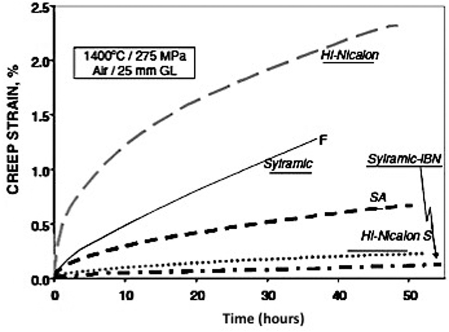
The creep resistance varies in inverse proportion to oxygen content, SiC grain size and amount of amorphous phase. It has been shown to be improved after high-temperature treatment under various atmospheres. Creep behaviour of Hi-Nicalon can be improved by high-temperature treatment that eliminates amorphous phase and organizes better carbon structure [48]. The similar effect was obtained on SiC Sylramic fibre [82]. The improvement of the creep behaviour of the Sylramic fibre was achieved by NASA by thermal treatments in selected environments to remove or alter the sintering aids, which led to Sylramic-iBN and Super Sylramic-iBN. The Sylramic-iBN seems to be superior to Hi-Nicalon-S in Figure 9 [82]. The Hi-Nicalon-S fibre does not contain sintering aids but has a finer grain size than SA and Sylramic-iBN fibres.
Oxide fibres
As oxides, they are resistant to oxidation at high temperature. The fine grain size necessary for high strength at low temperatures makes them prone to high-temperature creep. When subjected to high temperatures over long times, they are sensitive to grain growth. Nextel 610 fibre is limited by creep to <1000°C [40,83]. Nextel 720 fibre has higher creep resistance which allows use at higher temperatures (up to 1200°C). Sapphire (single-crystal Al2O3) fibres are also available [40,83]. Their cost and diameter (>50 μm) limit their use in composites [40,83].
Yun and Goldsby [84] have conducted studies on the tensile creep of polycystalline Nextel 610 and polycrystalline pure alumina fibre (Dupont alumina fibre) at temperatures from 800 to 1500°C. For both fibres, only a small portion of primary creep occurred followed by steady-state creep. The stress exponents for steady-state creep were found to be about 3 for Nextel, and 1 for Dupont alumina fibre. The possible corresponding creep mechanism is grain boundary sliding controlled by interface reaction (Nextel) and by Nabarro-Herring (Dupont alumina fibre) mechanisms, respectively. Activation energy of 460 kJ mol−1 was estimated on both fibres.
Lavaste et al. [85] and Pysher et al. [86] obtained results with some differences on Dupont alumina fibre. A larger steady-state creep exponent (n′ = 2) was estimated by Lavaste et al. [85], which indicates that the controlling creep mechanism is instead diffusion limited by interfacial reactions. Exponent larger than 1 (n′ = 1.36) was obtained by Pysher et al. [86], which also suggests that the creep mechanism is diffusion limited by interfacial rections. Apparent activation energies were quite close: 564 and 588 kJ mol−1, respectively [85,86]. The differences in the creep parameters that are reported in the literature can arise naturally from the different data processing used by the authors and the variability in test practice.
Creep rupture
Creep rupture is a phenomenon of importance for the durability of composites. Understanding and characteristics of creep rupture are useful for the evaluation of potential of fibres at high temperature. However, not so many papers have addressed the mechanisms of fibre creep rupture, and strength degradation at creep temperatures. For alumina-based oxide fibres, Lavaste et al. [85] reported stress/strain grain growth enhancement, and extensive homogeneous damage which consists of microcracks and cavities. For SiC fibres (and SiC monolithic ceramics), energy observation suggested that creep-induced micro-crack growth was to be a mechanism controlling the high-temperature fracture [77,87].
Mechanims of creep failure
The creep rupture for SiC fibres depends on the behaviour of thermally unstable phases in fibre and on fibre oxidation. These phenomena depend on the temperature and environment. For most of the SiC-based fibres, rupture times and strains at failure were found to be higher in air than in argon [44,46,48] under similar conditions of stress (450 MPa) and temperatures (1200 and 1600°C). For Sylramic, Tyranno SA and Hi-Nicalon S fibres, rupture times and strains at 1400°C were found about a factor of two larger in air than in argon [44,46]. Furthermore, the following factors have been shown to have a significant influence on the mechanical properties of SiC-based fibres: amount of oxygen, size of β-SiC crystals, state of crystallisation and quantity of free carbon [88,89].
In Nicalon fibres, the above-mentioned decomposition of the Si–C–O amorphous phase generates gaseous species whose diffusion through the fibre and reaction with free carbon are believed to create pores and defect in the fibre [48,66,67,68,69], which causes fibre strength degradation.
In air, the fracture of Hi-Nicalon fibres during the longest creep experiments (at low temperature or under low stresses) was mainly due to decrease of fibre cross-sectional area with growth of oxide layer on fibre surface and to pores formed during creep [48]. In conditions of higer temperatures and stresses (>1600°C, >450 MPa), a different fracture mode by necking was observed, whereas the thickness of the oxide scale remained limited [48].
In argon, most Hi Nicalon fibres failed after a very short period of time. A thin carbon layer formed on fibre surface from the active oxidation of SiC by the residual oxygen present in the surface of fibres and/or in the test atmosphere [48]. Fracture resulted from the consequential formation of flaws and/or diminution of fibre core diameter.
For Sylramic, Tyranno SA and Hi-Nicalon S fibres, the presence of a thin silica layer on the surface of fibres tested in air was assumed to minimize vapourization of thermally unstable phases and to be also capable of blunting surface flaws [44].
Tertiary creep was observed in vacuum at high temperatures >1450°C on Hi-Nicalon S and Tyranno SA(3) fibres [51]. An annular region made of pure carbon was identified, due to SiC decomposition [51]. The creep rate acceleration and fibre fracture would result from the decrease of the core diameter and associated increase of the stress [51].
Characterization of creep rupture
Evaluation of the creep rupture behaviour of fibres is based on the comparison of various characteristics. Thus, the Hi Nicalon fibre was found to exhibit much longer times-to-failure than Nicalon in air [48]. Then, plot of the average strengths measured on fibres crept at the same condition of deformation, time and temperature as a function of grain size[44], showed that the Sylramic-iBN fibre displayed the higher strength over Sylramic and Hi-Nicalon S, whereas Hi Nicalon was weaker, for this particular condition. However, this analysis required several assumptions. The comparison of creep stress–rupture time curves [44] appeared to be difficult because of scatter in data that was discarded and curve overlap.
Time/temperature-dependent strengths of SiC and Al2O3-based filament measured using stress-rupture, fast fracture and warm-up rupture tests were correlated into master thermal activation curves using the Larson–Miller parameter (Figure 10) [80,89]: Larson Miller master curves measured in air on SiC fibres (Sylramic, Sylramic-iBN, Hi-Nicalon) and oxide fibres (Nextel 610, Nextel 720) [44].
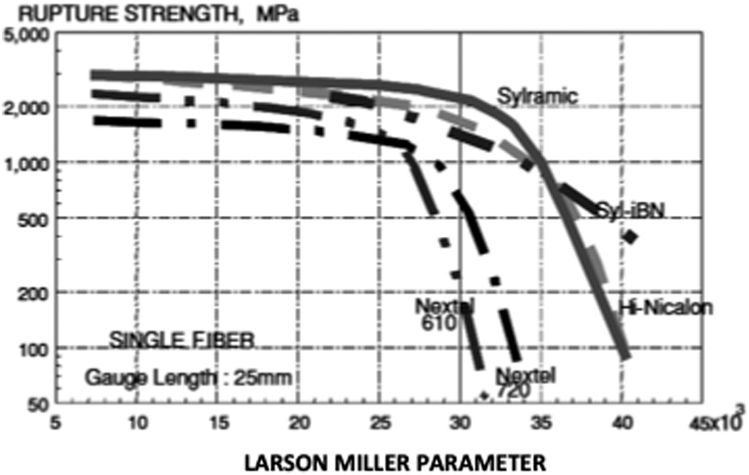
Here Qr is the effective stress-dependent activation energy for fibre rupture; R is the universal gas constant (8.314 J/mol-K); T (kelvin) is the absolute temperature for the rupture test and tr (hours) is the fibre rupture time.
Comparison of the master-curves shows the superior creep resistance of SiC-based fibres over oxide fibres in air. Hovever, the SiC-based fibres cannot be differentiated. The authors identified two distinct regions of degradation rate which is typical of the rupture of monolithic ceramics: the region with a small negative slope which is attributed to slow crack growth of inherent flaws, and the region with a much larger negative slope where the creep mechanisms seemed to favour the more rapid growth of the flaws or the nucleation and growth of new micro-cracks and cavities [80,89].
Originally, the Larson Miller parameter was destined to describe the equivalence of time at temperature and predict lifetime for a steel under the thermally activated creep process of stress rupture. The Larson Miller diagram allows an easy comparison of fibre resistances to creep rupture. However, it presents drawbacks for alternate analyses. Thus, as the LM parameter involves the log of time, the region of short durations is amplified, whereas long durations are compressed, so that the presence of two regions may be apparent only. Then, the LM parameter does not include explicitly the applied stress, so that the contribution of stress to slow crack growth and cavitation is not taken into account. Finally, the inherent variability of filament strengths is not considered in the analysis.
The fibre creep-rupture data were also analyzed in terms of Monkman–Grant (MG) diagrams which plot the log of fibre rupture time versus the log of fibre creep rate at various temperatures [44,80]. On MG diagrams, the log–log results at various temperatures typically fall on a set of parallel straight lines, according to Equation (5).
Figure 11(a) shows the best-fit MG lines in the air for log of average rupture times versus log of steady-state creep rate for various alumina-based fibres in air. The parallel segments represent the results of creep rupture tests at various temperatures under stresses between 100 and 500 MPa (O). Then, the segments at identical stress intervals do not overlap, so that the fibres can be compared with respect to temperature conditions and rupture times. It appears that the longer rupture time was obtained for the Nextel 720 fibres with the lower minimum creep rates. Best-fit MG lines in air for (a) oxide-based single fibres from 980 to 1200°C (data points are Nextel 610 CMC rupture results at 1000°C (X) and 1100°C (+)) and (b) SiC-based single fibres at 1200°C and the Hi-Nicalon fibre at 1400°C [44].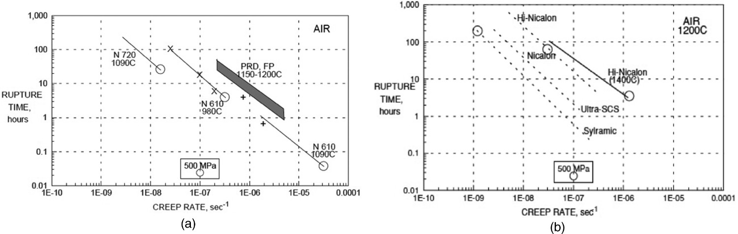
In Figure 11(b), the MG diagram was obtained for SiC fibre types that displayed a large transient creep stage and rupture during this stage. The minimum creep rate is the creep rate at rupture. The MG lines are parallel. Data obtained at 500 MPa, indicate that the Sylramic fibre seems to display the longer rupture time, and that the creep rupture time of Hi-Nicalon at 1400°C is smaller than that of Nicalon at 1200°C. In [85], the MG plot of stress versus time to failure allowed a better comparison of creep resistance of FP and PRD alumina-based fibres at 1600°C.
Characterization of creep fracture strength is not straightforward because several parameters need to be considered: on the one hand, scatter in strength data, that is inherent to brittle materials, and, on the other hand, microstructure, applied stress, rupture time, temperature and environment. A unique combination of these latter parameters was not defined. As indicated above, the Larson-Miller combines only three parameters. The applied stress does not appear explicitly despite its significant contribution to creep failure. It is masked in Qr the effective stress-dependent activation energy for fibre rupture. A robust model of fibre creep rupture and closed –form expressions of strength degradation during creep are still missing for proper analysis of stress–rupture time diagrams and sound predictions of composite creep fracture. Such a model has been developed for the oxidation activated slow crack growth in SiC-based fibres.
Strength degradation by environment-activated slow crack growth
At temperatures below the creep regime threshold (<1200°C), it has been shown that subcritical crack growth operates on SiC-based fibres under stress in air. This delayed fracture mechanism has been the subject of a certain amount of experimental and modelling effort [90–95]. It was found that the rupture time under constant stress diminishes sharply to a plateau with increasing oxygen fraction. For oxygen concentrations >15–20% oxygen was in excess for the chemical reactions [95]. Slow crack growth results from the consumption of free carbon at grain boundaries and the contribution of local stresses induced by the SiC → SiO2 transformation at crack tip [95]. The flaws at crack initiation are randomly distributed. A closed form expression for time-dependent stress rupture relationship is based on the power law for crack rate and on linear fracture mechanics [96]:

where P(t,σ,v) is the failure probability at time t, under constant stress σ, for a filament with volume v, m and σ
0 are statistical parameters. t* is a stress-dependent scale factor: 
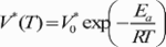 where T is temperature, V0* is temperature independent material parameter, Ea
is activation energy, R = 8.314 J k−1 mol−1.
where T is temperature, V0* is temperature independent material parameter, Ea
is activation energy, R = 8.314 J k−1 mol−1.
The intrinsic parameters are estimated by fitting the closed-form expression for statistical distribution of filament rupture times to experimental data [96,97] (Figure 12), whereas tow lifetime data are affected by structural phenomena (Figure 12). Filament strength degradation and rupture times were predicted using slow crack growth-based model [96]. Stress-rupture time diagram for Hi Nicalon single filaments and tows [94]. Rupture time degradation results from oxidation activated slow crack growth in air. The filament lifetimes at given strength display a statistical distribution as a result of random distribution of crack inducing flaws. The equation of best-fit line for tow data is also given.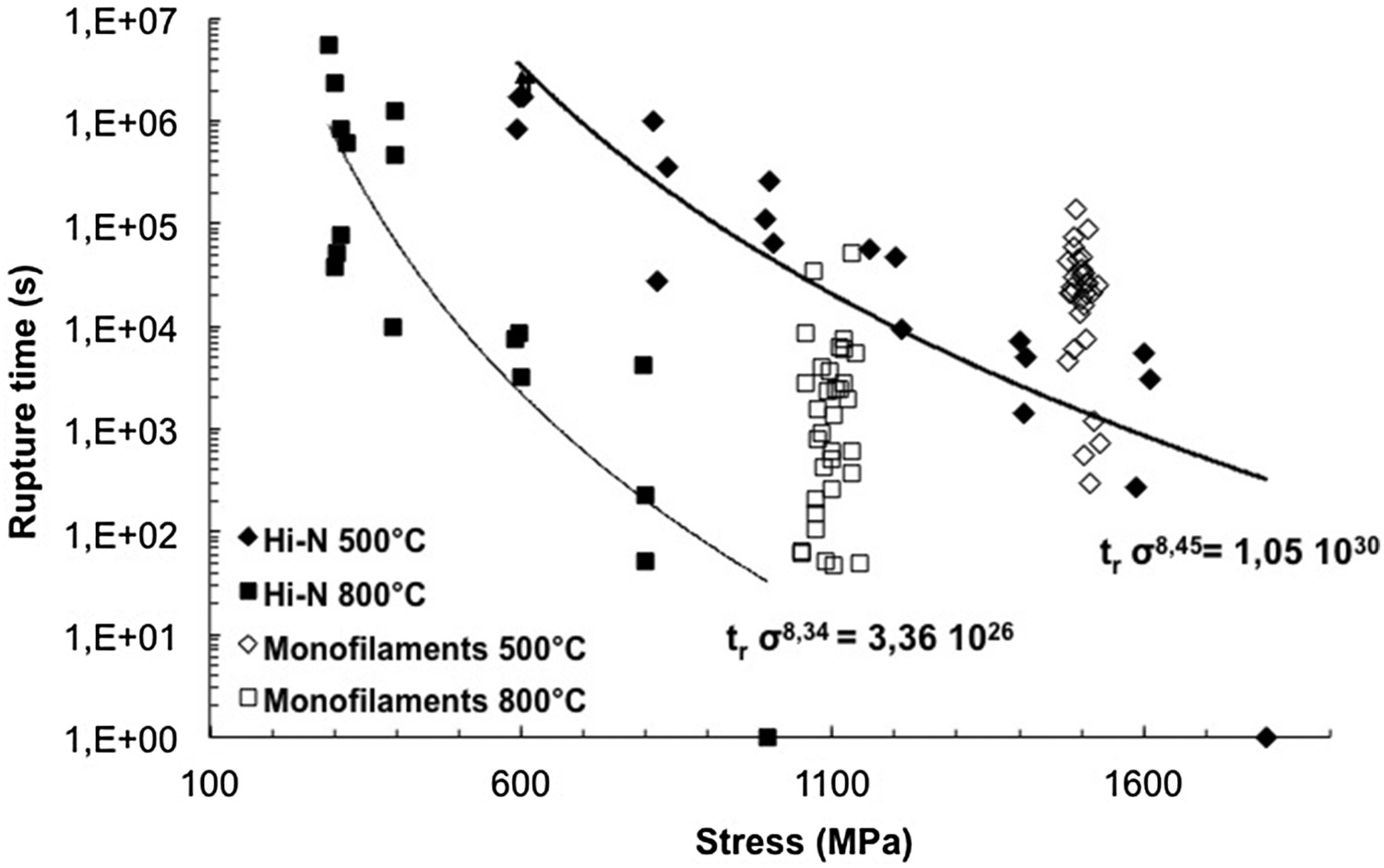
Tyranno SA3 and Hi-Nicalon S fibres were found to be more resistant to slow crack growth than the Hi-Nicalon that was superior to the Nicalon fibre. The contribution of oxygen activated slow crack growth to creep fracture at temperatures >1600°C has not been examined yet.
Creep of composites
Creep testing
Creep tests are used for the determination of creep behaviour in the selected controlled atmosphere, through the measurement of dimensional changes at constant high temperature and constant load or stress. They are useful for modeling long-term applications which are strain limited. They provide the prediction of life expectancy before service.
Inert atmosphere is required for the determination of intrinsic time-dependent creep properties. Vacuum or argon is the most employed. Tests can also be performed in specific atmospheres that prevail in-service, like air or steam. The SiC/SiBC, SiC/Si–B–C and enhanced SiC/SiC composites and oxide composites that are claimed to be insensitive to oxidation are tested in air [34,35,36,63].
For detailed creep studies, tests at constant load or stress are preferred to tests at constant strain rate or to cyclic fatigue. Tensile tests are mostly employed for CMCs. No paper reported creep results from compression tests. Very few authors determined creep data in 3-point [63] or 4-point [98] bending. The creep behaviour was described by load–displacement (deflection) curves. The bending tests are not recommended for composites because the elastic beam theory is not a proper foundation for the determination of stresses.
Tensile testing conditions and procedure are detailed and specified in standards [99]. An experimental technique for tensile creep testing of CMCs was discussed in [100]. Two different types of installation can be used: a universal test machine, or a creep-testing rig. The testing rig must be equipped with a system to allow smooth loading of the specimen(s). The unloaded specimen is first heated to the test temperature, and the gauge length is measured. The predetermined load is applied quickly without shock. It is maintained at a constant level for a specified time or until rupture. The variation in gauge length is recorded in relation to time.
Creep tests are generally long-term tests, low loads are selected. Deformations are small and precision strain measurement is required. Creep stress, strain and strain rate are derived from test results. The creep constants can then be extracted from the creep strain rate using the above equations. Emphasis is generally placed on the minimum strain rate at stress and temperature. The tests are interrupted when the time-to-failure is not sought. During creep rupture tests, emphasis is placed on time-to-failure at stress and temperature. A stress-rupture time diagram is produced. Higher loads are generally selected, in order to reduce creep test duration.
Creep tests at high temperatures (>1200°C) present several practical difficulties, much care and precision strain measurement are required, and artefacts must be avoided. Let us illustrate this critical issue by these two examples.
First, during the application of the predetermined load, the loading rate can have a dramatic effect on the subsequent accumulation of creep strain. When the force is applied at a lower rate, load redistribution between the fibres and the matrix can already occur, so that a load lower than the expected load can operate on the weaker constituent. When the matrix has the lower creep resistance, fast loading rate may hence cause matrix cracking, which in turn implies a higher load on the bridging fibres and leads to higher rate composite creep. Matrix microcracking may be avoided during loading at a sufficiently low rate, and the creep life of the composite may increase considerably.
Second, it was shown by accident [101] that the presence of oxygen concentration about 20 ppm in argon was sufficient to favour oxidation influence on creep and obtain failure times similar to that of air-tested composites.
Tensile tests under a constant force are also preferred for fibres. Details can be found in various papers [48,51,67,68,84,85,102,103]. In [51], the creep tests were performed on a tensile device designed for testing carbon fibres at temperatures up to 3000°C. Electric tension was applied to the fibre for heating in the secondary vacuum (residual pressure ≈ 10−4 Pa).
In [89], two types of tensile tests on fibres were utilized to produce stress–rupture time diagrams: stress rupture (constant stress and constant temperature), slow warm-up (constant stress, constant rate of temperature change).
The bend stress relaxation (BSR) test was utilized to screen creep performances of fibres. For this test, a short length of fibre is held at constant strain in a pure bending mode while being thermally treated for a specific time at constant temperature in a controlled environment [104].
Tensile creep behaviour and recovery
Several creep test results were reported on commercial composites made by different manufacturers. As a consequence, these composites may present differences in microstructure and composition, particularly at the fibre/matrix interface or in the matrix. Details on composition are generally not available. In [63], Chermant synthetized the results of more than 10 years of in-house research on the creep of various lots of ceramic (SiC, Si–B–C (Table 1)) or glass-matrix (MLAS, YMAS (Table 1)) composites reinforced by carbon or SiC (Nicalon or Hi-Nicalon) continuous fibres, at temperatures in the ranges 1273–1673 K (SiC-based matrices) and 1173–1473 K (glass-matrix composites). The tensile creep curves of strain or strain rate versus time for these CMCs tested in argon or for the SiC/Si–B–C tested in air, exhibited the two stages of primary and steady/pseudo-steady creep and no tertiary creep.
The Nicalon/Si–B–C composite (Table 1) tested at 1200°C in argon exhibited primary creep only, even during long tests (duration exceeding 85 h) [34].
Only the transient creep stage was observed on SiC/SiC, SiC/SiBC, Enhanced SiC/SiC (Table 1) and SiC/Al203 reinforced with Nicalon and Hi Nicalon fibres, tested in air at 1600°C and stresses >90 MPa [35,36,105,106]. Three stages of creep can be found at low stresses for SiC/SiC composites, but there is no tertiary stage or even no secondary stage at high stresses [105]. Decreasing creep rate was observed at stresses below 168 MPa for melt infiltrated Hi-Nicalon S/SiC at 1615°C in air [61]. Manifest secondary creep was not identified during tests interrupted after 100 h. At the stress of 172 MPa, specimen rupture occurred after the increasing rate of deformation with time. The composite was considered to be relatively creep resistant at stresses ≤103 MPa, which was attributed to the creep-resistant nature of the reinforcing fibre. This behaviour is consistent with that of similar SiC/SiC systems.
Nextel720/alumina and Nextel alumina-mullite composites consisting of a porous oxide matrix reinforced with 0°/90° woven fibres (fibre volume fraction ∼0.40) exhibited primary and secondary creep, but no tertiary creep regime in the air at 1000–1200°C with tensile creep stresses ranging from 80 to 160 MPa [58]. Strains at fracture were in the range 0.1–1.5% depending on stress and temperature. The reported secondary creep rates were in the range 10−5 to 10−9 s−1.
Strain recovery during unloading
Recovery is the process in which an unloaded material recovers a part or all of the strain accumulated during loading. Time-dependent strain recovery is a feature of the viscoelastic response of materials during primary creep. The study and modelling of creep recovery have received little attention for CMCs. A few authors have reported experimental data [37,58,107]. Holmes et. al. investigated the creep recovery behaviour of 0° and 0/90° SiC/CAS (Table 1) and SiC/Si3N4 composites at elevated temperatures [107]. On unidirectional and 2D woven SiC/Si3N4, 50% of the total creep strain which accumulated after 200 h at a stress of 200 MPa and temperature of 1200°C was recovered within 25 h of unloading. A similar trend was observed on unidirectional and 2D woven SiC/CAS composite at 1200°C. For a loading history involving 100 h of creep at 60 MPa, followed by 100 h of recovery at 2 MPa, approximately 27% of the prior creep strain was recovered for the 0° composite and 49% for the 0°/90° composite. The amount of recovered strain in the CMCs investigated by Holmes et al. [107], is much higher than in the monolithic ceramics.
Trend in creep recovery behaviour at 1200°C was examined on 2D woven enhanced Nicalon/SiC (Table 1) [37]. The specimen was loaded at 1200°C to creep stress (140 MPa) quasi-statically and held at that stress for a duration of approximately 2 h. It was then unloaded and held at zero stress level for an equivalent amount of time. At the end of the recovery time, the specimen was reloaded to a higher stress level. The procedure was repeated until the specimen failed. From the creep curves (Figure 13(a)), the conclusion was drawn that the material has a tendency to recover the instantaneous as well as the accumulated creep strain over a period of time and the recovery behaviour is independent of applied load during creep [37]. These conclusions are somewhat questionable due to irreversible deformation that may occur at stresses close to fracture.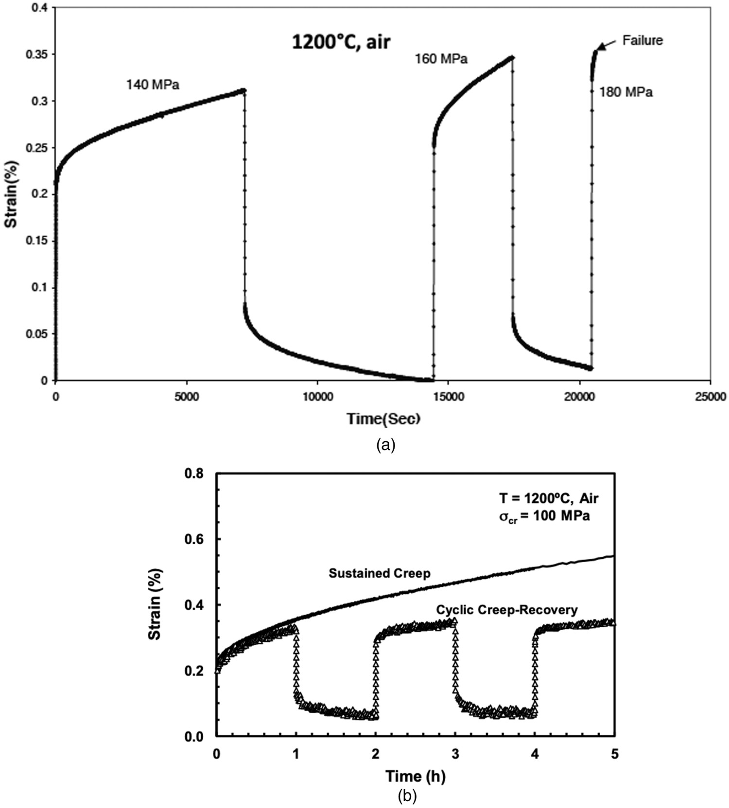
Recovery tests were performed on the above-mentioned 2D woven N720/Alumina composite at 1200°C in air and steam [58], consisting of loading at 20 MPa/sec to the creep stress (100 and 125 MPa) and, after 1-h hold time, unloading at the same rate to the minimum stress fixed at 2 MPa. The strain versus time curves obtained showed appreciable recovery at 2 MPa (Figure 13(b)). Then, the following natural consequences of stress relaxation during recovery were observed: first, a significant reduction of the primary creep with cycles, then, a significant reduction of overall strain accumulation [58].
The recovery trends can be interpreted in the light of underlying creep behaviour. The creep curves for different stress levels at 1200°C for the enhanced Nicalon/SiC composite, showed a dominant primary creep stage [37], whose time length decreased significantly with increasing applied stress [37]. As recovery requires viscoelastic response, it depends on hold time versus primary creep time and on applied stress. Under higher stress, the primary creep time becomes shorter. Therefore, depending on applied stress, it may become shorter than the hold-time, so that the response is viscoplastic. As a consequence, partial recovery would be observed. At lower stresses, as primary creep time is longer, it may exceed hold time, so that the response on unloading is viscoelatic and complete recovery can be observed.
Primary creep time for 2D woven N720/Alumina was significantly longer than hold time (about 20 h against 1 h) [58]. Therefore, the response during unloading was probably viscoelastic leading to complete recovery. Recovery tests provide a sound technique to differentiate viscoelasticity and viscoplasticity in creep behaviour.
Creep properties
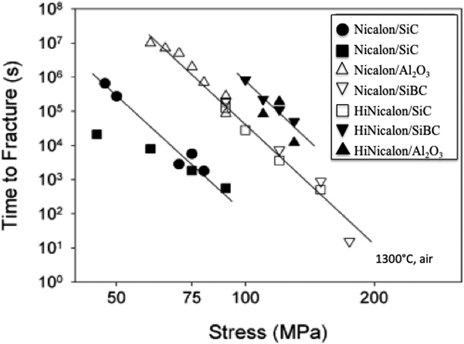
For most CMCs, the secondary and the tertiary stage do not exist normally. Authors placed generally focus on the minimum creep rate. Similar to homogeneous materials, analyses of creep used plots of minimum creep strain rate as a function of stress as well as stress rupture time diagrams. Figures 14 and 15 show log plots of creep data [35,36]. It can be noted that they display a significant scatter and that they were not fitted satisfactorily by a straight line. In Figure 14(a), Nicalon/SiC, Hi Nicalon/SiC and enhanced SiC/SiC (Table 1) cannot be distinguished. By contrast the stress-rupture time diagram lead to the following ranking by increasing order of creep performances in Argon: Nicalon/SiC < Enhanced Nicalon/SiC and Hi-Nicalon/SiC [108]. Figure 14(b) permits ranking of composites with respect to minimum stress rate in air, which is consistent with ranking based on rupture time (Figure 15) [35]. Hi Nicalon reinforced SiC, SiBC or Al2O3 were found superior to their Nicalon reinforced counterpart. Furthermore, the SiBC or Al2O3 matrix composites were superior to their counterpart with a SiC matrix. For most CMCs, the minimum creep rate is in the range 10−5 to 10−10 s−1. Comparisons of the stress/minimum creep rate (a) relations for Hi-Nicalon/SiC, Enhanced Nicalon/SiC and Nicalon/SiC at 1300°C in argon [108]. (b) Relationships for Nicalon/Al2O3 and Hi Nicalon/Al2O3 as well as for Nicalon/SiC, Nicalon/SiBC, Hi Nicalon/SiC and Hi Nicalon/SiBC samples tested in air at 1300°C [35]. Stress-rupture time diagrams for SiC/Al2O3, Hi Nicalon/Al2O3, Nicalon/SiC, Nicalon/SiBC, Hi Nicalon/SiC, Hi Nicalon/SiBC samples tested in air at 1600°C [35].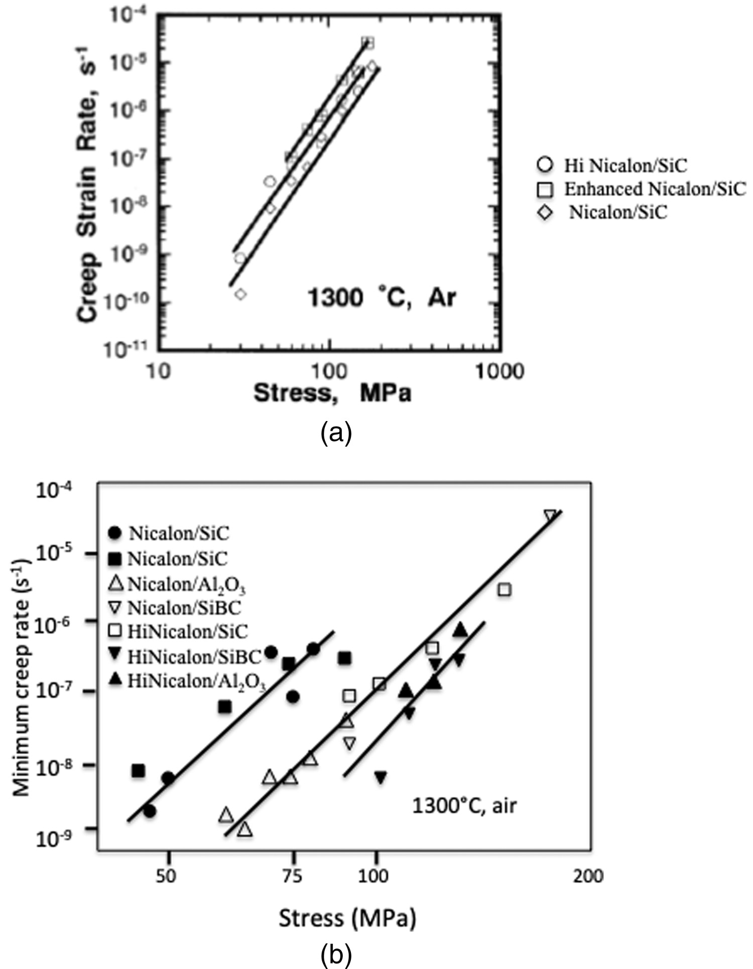
Although only transient creep strain was mostly found to exist, a few authors, estimated stress exponents from the slope of the log plots of minimum strain rate versus stress, in accordance with the steady-state power law (Equations (3)and (4)) [36,106,108,109].
Zhu et al. [36,106,108] obtained values for the enhanced and standard Nicalon/SiC composites in air and argon much higher (8–9) than the stress exponent (n′ = 1–2.5) for the creep of Nicalon™ fibres [67–69]. In a severe-matrix-cracked Al2O3/SiC composite, the estimated stress exponent for creep of the composite was consistent with that of the Al2O3 fibre [109]. In Nicalon/glass-ceramics, it is also the same as that of Nicalon™ fibres [73]. From the comparison of the slope of the log plots of minimum strain rate versus stress with fibre stress exponent, the subsequent interpretation of these results was that the fibre controlled totally or partly composite creep. Although fibre control of composite creep may be a reasonable phenomenon, the approach lacks physical foundation, and it was not followed by other authors. It is based on the Equation (3) that has been established for steady-state creep from theoretical creep mechanisms in homogeneous materials like ceramics or metals (Section ‘Secondary creep’). It cannot be applied to creep rate data for time-dependent primary stage. Proper analysis of composite creep data requires appropriate robust models of composite creep behaviour.
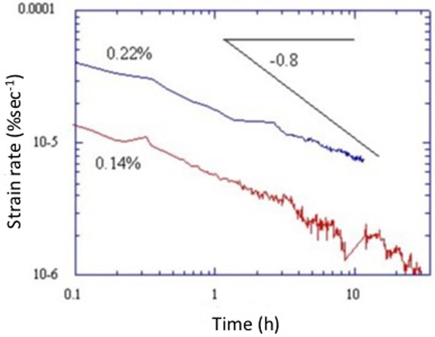
Figures 16 and 17 show log plots of creep rate versus time for Nicalon/Si–B–C (Table 1) and Nicalon/SiC composites at 1200°C in argon. The creep rate decreases steadily according to Equation (2) with the time exponent greater than that of stable Nicalon fibre in the primary stage of creep (time exponent in Equation (2) p′ > −0.8) [34]. For Nicalon/Si–B–C with saturated matrix cracking (Figure 16), the creep rate data closely fit the power law with time exponent p′ = −0.8, after a certain time t
0 (generally longer than 1 h). Which indicates the significant contribution of Nicalon fibre to composite creep rate in the presence of severe matrix cracking. Matrix cracking was created during a preliminary loading cycle (stress rate = 100 MPa/min) to maximum strain ε
0. For ε
0 ≥ 0.8%, the fibres were completely debonded from the matrix (Section ‘Mechanical behavior under tensile loading’), and the load was carried essentially by the longitudinal fibres. Slower creep rate for Nicalon/SiC is shown on Figure 17, which was logically attributed to higher creep resistance and stiffness of the SiC matrix when compared to the Si–B–C matrix. Creep rate curves for a damage strain ε
0 = 0.8% at various applied constant stresses in argon for the Nicalon/Si–B–C composite and at 450 MPa and 1200°C in argon for a Nicalon NL202 fibre [34]. Creep rate curves for Nicalon/SiC composite under a constant stress of 150 MPa (ε
0 = 0.14 and ε
0 = 0.22%) at 1200°C in argon [34].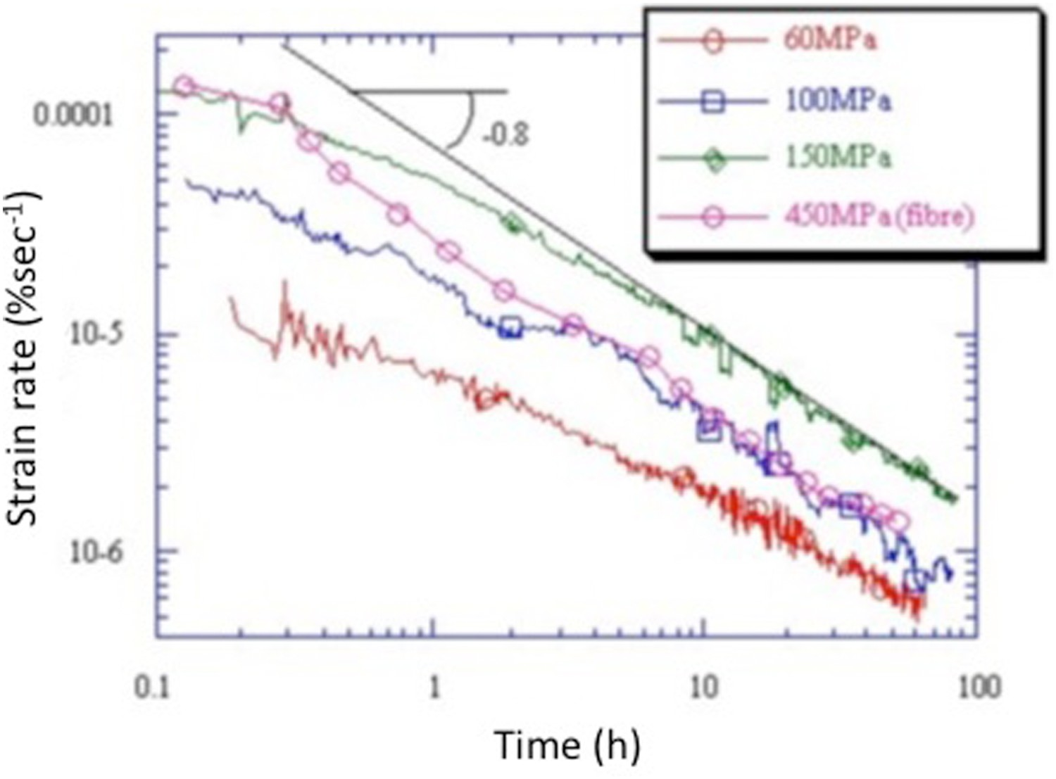
Creep mechanisms
The results reported in [63] on the extensive inspection by microscopy (optical, SEM, TEM) of the CMCs creep tested in argon (except SiC/Si–B–C, see Section ‘Tensile creep behavior and recovery’) revealed several types of damage: fibre/matrix debonding, matrix microcracking, yarn/yarn debonding, fibre/yarn bridging, fibre pull-out, fibre fracture, etc. These damage modes are currently observed during tensile tests at room temperature, as discussed in Section ‘Mechanical behavior under tensile loading’. They have also been observed by other authors on various CMCs: SiC/Si3N4, SiC/C, SiC/Al2O3, SiC/mullite, Al2O3/SiC [see references in 63]. C/SiC and SiC/SiC have shown the following microcracking sequence in argon [110,111]: first microcracks are created, then the opening of the transverse microcracks and development of interyarn longitudinal cracks. It is worth pointing out that new matrix microcracks did not appear during creep.
Microscopy showed that the matrix cracks in SiC/Si–B–C (Table 1) tested at temperatures < 1573 K in air are filled by a glassy phase [63], which protects the fibre against oxidation. TEM and HREM revealed several changes at lower length scales such as (i) interlayer microcrack extension in the multilayered SiBC matrix, involving deflection and bridging by carbon ribbons [63], (ii) lenticular pores in the pyrocarbon interphases, (iii) growth of SiC nanocrystals in the SiC fibres, and (iv) growth and orientation of basic structural units in the C fibres. No dislocation motion was detected, and, diffusion phenomena are unexpected at temperatures below 1828 K for SiC and 2423 K for carbon.
Then, from this phenomenological approach, Chermant drew the conclusion that the creep of SiC-based matrix composites in argon is controlled by a damage creep mechanism [63]. In the glass-ceramic matrix composites, the matrix is viscous at temperatures >1273 K and the creep of glass matrix composites is controlled by the fibres. He put forward the following scenario for the SiC-based ceramic matrix composites: a first saturated matrix cracking (no new cracks were observed) followed by the opening of the transverse microcracks and associated inter-yarn debonding, and microcracking in the matrix of longitudinal yarns. Depending on the temperature and stress, the SiC fibres can creep but not the carbon fibres at temperatures below 1600°C.
The influence of the degree of matrix cracking on primary creep of 2D Nicalon/Si–B–C composite was examined experimentally [34] and by modelling (Section ‘Models of creep deformation’). The degree of initial matrix damage was controlled through the maximum strain ε
0 applied during a preliminary loading cycle (stress rate = 100 MPa min−1). Then the creep tests were conducted at lower load. The values of ε
0 were selected according to the damage sequence described in Section ‘Mechanical behavior under tensile loading’: when ε
0 ≥ 0.8%, fibres in the loading direction are completely debonded from the matrix, when 0.2% ≤ ε
0 < 0.8%, they are partially debonded from the matrix. When ε
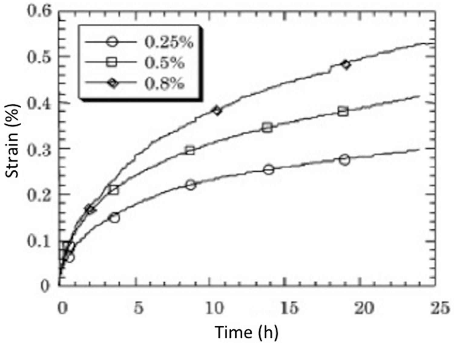
0 < 0.2%, matrix cracks are located within the intertow matrix and in the transverse minicomposites, and they are deflected by the longitudinal minicomposites, so that there are no cracks within these minicomposites (Figure 18). Figure 19 shows that creep deformations are commensurate with ε
0, which highlights the progressive reloading of the longitudinal fibres during creep. Creep deformations < 0.3% for ε
0 < 0.25% when composite creep was controlled by the debonded minicomposites (Figure 18). Since the stress at initial damage was larger than the creep stress of 100 MPa, propagation of debond cracks or creep of the intratow matrix within the longitudinal minicomposites may have occurred. Larger deformations were measured when ε
0 > 0.3%, i.e. when cracks were initially present in the longitudinal minicomposites. Schematic diagram showing a cracked transverse tow with crack deflection by a longitudinal tow in a 2D woven SiC/SiC composite, when ε
0 < 0.3% [34]: (1) Intertow matrix crack opening; (2) intertow matrix/longitudinal minicomposite debonding; (3) Intratow matrix creep; (4) Fibre creep; (5) Matix cracking in longitudinal tow at high stress. Creep curves for Nicalon/Si–B–C at 1200°C and 100 MPa in argon for various initial damage strains ε
0 [34].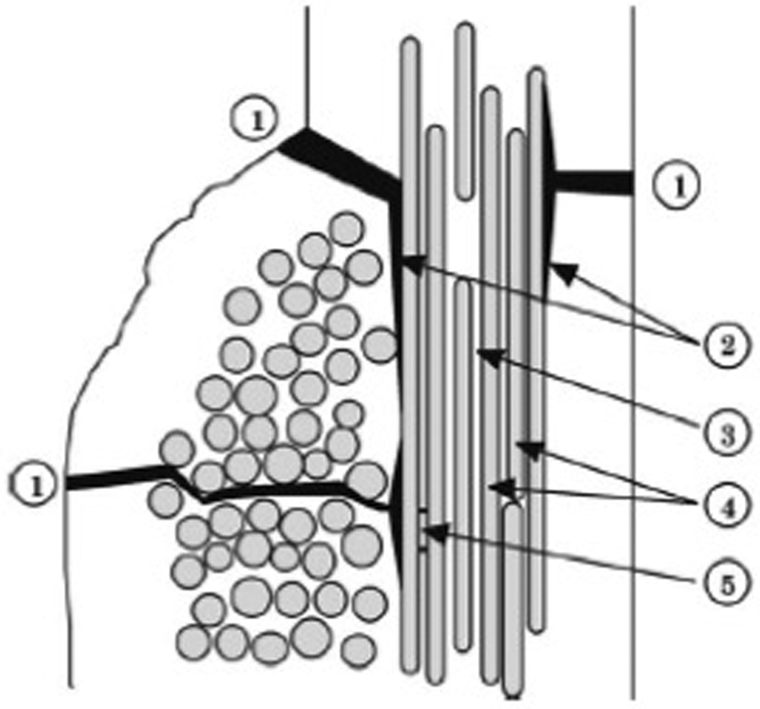
Microstructure/creep behaviour relationship
Creep in uncracked composites is controlled by stress transfer. The less creep resistant component (fibre or matrix) sheds load over time to the more creep resistant component.
Basic principles of the influence of fibre/matrix creep rate mismatch on stress state can be defined on the basis of creep mismatch ratio defined as 
The thermal expansion mismatch between the fibres and the matrix may generate stresses. If the coefficient of thermal expansion of fibre (αf ) > that of matrix (αm ), when CMR < 1, the relative deformation of fibres is increased at high temperatures above the processing temperature, which causes reloading of the matrix and increased further unloading. The opposite effect is obtained when αf < αm for CMR < 1 or when the creep temperature is lower than the processing temperature. Then, for SiC/Si3N4 and SiC/CAS (with αf > αm and CMR < 1), the residual stresses that develop in composite can provide an additional driving force for strain recovery, in addition to the intrinsic recovery process for monolithic ceramics [107]. By contrast, in SiC/SiC composites, the SiC fibres have a coefficient of thermal expansion slightly lower than that of the matrix. As a consequence, the thermally induced residual stresses are quite low. If any, tensile stresses would develop in the fibre at high temperatures.
Further behaviour of matrix and fibres depends on stress vs. strength for cracking, and on temperature for thermal degradation. Matrix cracking leads to increased loading on debonded fibres. Following the initial matrix cracking, additional composite degradation may occur by several different mechanisms. The growth of the fibre/matrix interface debond can occur due to the difference in the radial creep strain of the fibres and that of the matrix [114,115]. In oxidizing environments, the interfacial properties (and hence the creep behaviour) can be altered by removal of the interface layer or by closure of the interface by oxidation of the fibre and/or matrix. Creep fracture is caused by fibre fracture when stress on fibres exceeds fibre strength, because of either fibre reloading or weakening as a result of creep- or oxidation-induced flaw growth in the SiC fibres [116,93–95].
Creep of CMCs can fall into either regime. However, the creep rate depends on temperature, stress state and time [117] so that CMR may vary, especially in intermediate situations when the creep resistance mismatch is initially small. The above principles are insufficient to anticipate composite creep behaviour. Furthermore, there are additional factors that affect composite creep behaviour, that are not taken into account such as interfaces, fibre volume fraction, etc. Micromechanically based models of creep behaviour allow better understanding of the interaction of fibre and matrix creep behaviour and prediction of composite creep curve.
Models
The main models for the understanding and prediction of composite creep address the two main steps of creep behaviour, i.e. on one side time-dependent deformation, on the other side, fracture.
The models of deformation consider the composite constituents as physical entities (fibre, matrix and interfaces), their respective properties and the eventual presence of damage. The models of composite fracture assume that fracture results from the propagation of matrix cracks or from fibre failure.
Models of creep deformation
In the approach of creep for homogeneous materials, the equation of secondary creep rate (combination of Equations (3) and (4)) was established from models of theoretical fundamental underlying creep mechanisms. This equation is then used as a reference to assess the underlying mechanisms from experimental creep behaviour, and investigate the influence of material parameters. As discussed in Section ‘Mechanical behavior under tensile loading’, the mechanical behaviour of composites is controlled by the behaviour of constituents. Thus, a pertinent approach to the creep behaviour of composite consists in modelling the composite creep behaviour from the interaction of creep behaviour of fibre and matrix. Theoretical approaches to composite creep behaviour are often based on a microcomposite unit [114,115,117–122]. Microcomposite and minicomposite are significant entities for 2D and 3D woven structures [section ‘Mechanical behavior under tensile loading’, 52–54].
Microcomposites with creeping matrix and fibres
In [117], models were established for the description of the creep behaviour of a theoretical composite system, given the creep mismatch ratio and the interfacial shear strength, for different fibre creep rates, volume fractions, ambient temperatures and applied stresses. The predicted creep curves were compared to experimental results obtained at 1200–1400°C and 100–450 MPa in argon on SiC/SiC microcomposites consisting of single Hi Nicalon (with low elastic modulus, Table 3) or Carborundum (large elastic modulus) fibres coated with a CVD carbon interlayer and a CVD SiC matrix [117]. The CVD SiC matrix was Si-rich with creep properties poorer than those of stoichiometric SiC matrix. The models highlight quantitatively the influence of various material parameters (constituent properties, interfaces, damage) on composite creep, and they predict the resulting creep strain curves. These curves allow further analysis of composite creep.
Microcomposite free of matrix cracks [117].
The creep of uncracked microcomposites was modelled using a simple rule of mixtures approach [118,122]. The model [117] assumes no residual stresses, instantaneous loading, and perfect load transfer across the interface. The applied tensile stress is initially distributed according to the elastic constants and volume fractions of the fibre and matrix.
Primary creep laws were used for modelling the creep behaviour of the fibre and the matrix since these expressions are the best currently available [123,124] although their use for complex load histories is probably inappropriate.
The total creep strain of each constituent consists of an elastic and a creep component, according to the following equation in the presence of creep mechanisms that are thermally activated processes as discussed in Sections ‘Mechanisms of creep in ceramics’ and ‘Creep behavior’ on creep of ceramics and fibres:
where ε is the creep strain, σ is the applied stress, t is the time, T is the absolute temperature, E is the Young's modulus, n is the creep stress exponent, p is the creep time exponent, and P = pQ/R, where Q is the activation energy and R is the gas constant.
The composite strain over a time Δt interval is derived from (14):
Since the strain rates in each of the composite constituents are constrained to be equal, the change in stress in either constituent at any time can be derived. The fibre stress rate, for example, is [118]:
The evolution of the fibre and matrix stresses calculated from the rule of mixtures model illustrates the load sharing change induced by the creep of matrix and fibre (Figure 20). In Figure 20(a), the stresses on both components start out equal (to applied stress = 100 MPa) for the Carborundum/SiC microcomposite since the fibre and matrix have the same elastic modulus (Table 4). For the Hi-Nicalon/SiC microcomposite, the initial stress on the matrix is higher than that on the fibre (the strains must be equal) since the matrix has a higher elastic modulus than does the fibre (Table 4). Thus, the matrix carries a significantly larger part of the applied stress when compared with the Carborundum microcomposite. Note that the elastic misfit stresses relax very quickly and it is reasonable to assume that if there were residual stresses in the microcomposite, they would also quickly dissipate [119]. In both microcomposites, the matrix stress, σm , decreases to a constant value at the conclusion of the simulation. As a consequence, matrix cracking cannot occur. The fibre stress, σf , increases much more significantly for the Carborundum/SiC microcomposite, since the matrix carries a smaller part of the load than the matrix of Hi Nicalon/SiC microcomposite.
Figure 20(b) shows the changes in the stress state during creep of a theoretical microcomposite for which the matrix is the more creep resistant phase (CMR > 1) as might be expected for a stoichiometric matrix. The matrix creep rate was taken one order of magnitude lower than that observed. The initial fibre and matrix stresses are the same as in the earlier case, but the matrix now accepts load shed from the fibre. The amount of stress transferred is low since the matrix stress is initially much higher than the fibre stress, as a result of initial load sharing. Therefore, the creep strain arising from the elastic loading of the matrix in the initial stage of the simulated experiment is lower than in the CMR < 1 case. However, it can be anticipated that depending on initial load sharing (the amount of load carried initially by the matrix), higher matrix stress increase can occur, that would cause matrix crack. Evolution of fibre and matrix stresses during microcomposite creep at 100 MPa and 1300°C calculated from the rule of mixtures model: (a) CMR < 1 (The Hi Nicalon microcomposite results have been shifted 200 min for clarity); (b) CMR > 1 (theoretical Hi Nicalon-based microcomposite coated with a matrix that creeps at an order of magnitude lower rate than that observed) [117].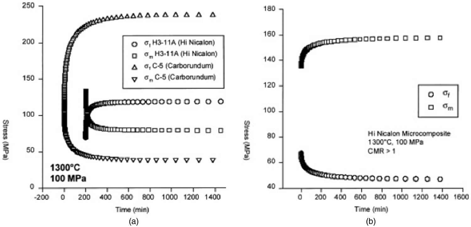
Fibre and matrix creep properties used in creep model [117].
Figure 21 compares the predicted and experimental creep behaviours of the SiC/SiC microcomposites [117]. Predictions and experiments also evidenced creep strain increase with matrix volume fraction. Park and Holmes predicted similar trend on SiC(SC6)/Si3N4 composite with CMR < 1 and without matrix cracks [119]. Comparison of the creep behaviour of Carborundum- and Hi Nicalon-based microcomposites. The experimental results are shown by the dotted lines and the rule of mixtures models by the lines [117].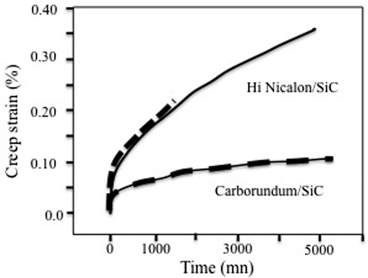
Microcomposite with matrix cracks [119]
A matrix crack and the associated fibre/matrix debond generate a shear lag (Figure 22). The stress on fibre increases in that region and reaches maximum σ
1 = σ
app/Vf
in the completely debonded part of microcomposite, σ
2 is the stress on the fibre along the debond crack, σ
3(t) is the stress on fibre in the intact part of microcomposite. Ld
is the debond length, that varies in inverse proportion with the interface shear stress. Schematic diagram showing a portion of specimen, a transverse crack in the matrix, the associated debond crack and the stress state in the fibre.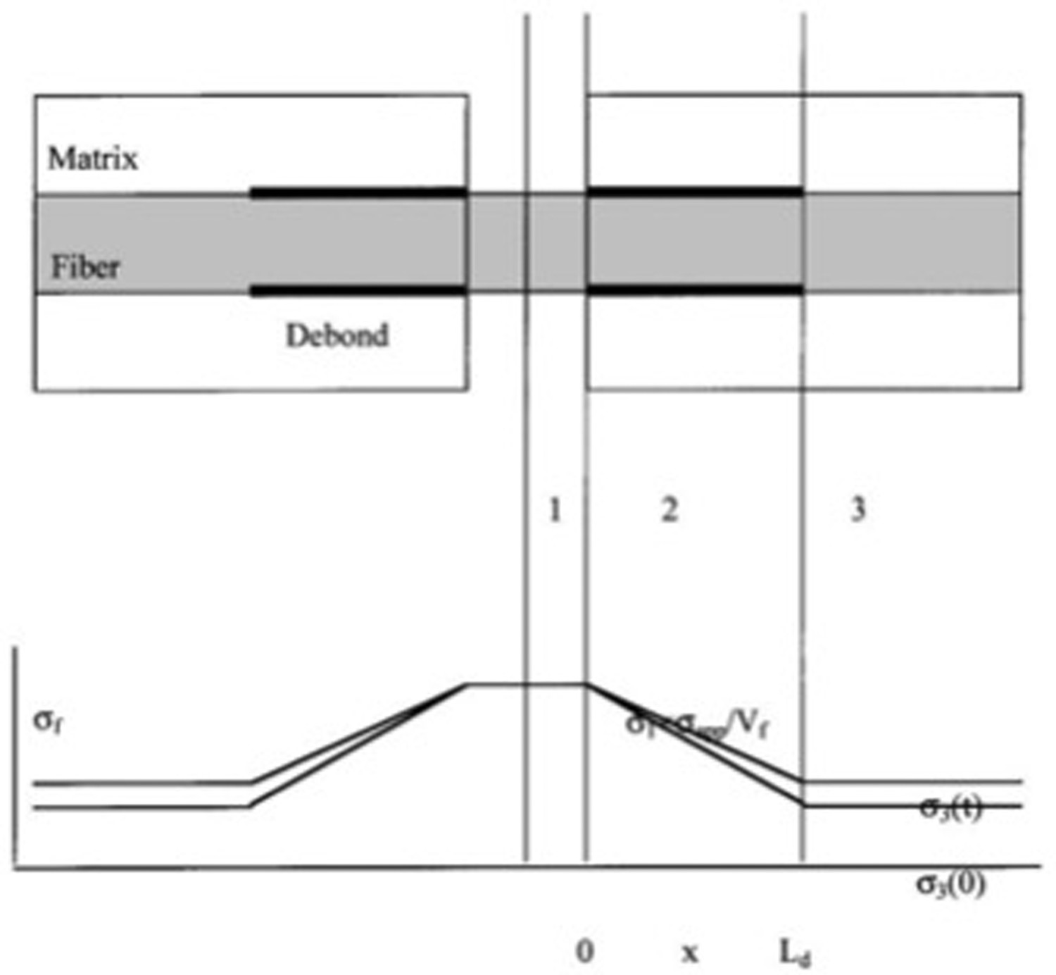
The time dependence arises from the time dependence of σ
3 as derived from the rule of mixtures algorithm. If the debond does not propagate, there is a change in interface shear stress τ which results in a decrease in the slope of the σ
2 versus × line with time as indicated in the Figure 22. Propagation of a debond would also result in a decrease in τ [114]. The overall creep strain of the microcomposite is the summation of the creep strains, εi
, from each of the three regions of stress state, defined by σ
1, σ
2 and σ
3 (Figure 22), i.e: Comparison of the creep of cracked and uncracked Hi Nicalon-based microcomposites at 1200°C and 200 MPa. The results of the rule of mixtures and cracked composite creep models are shown by the solid lines [117].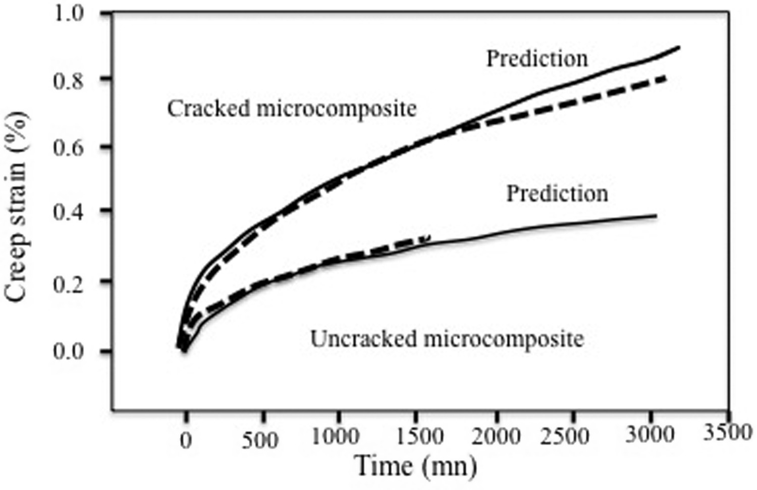
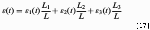
where εi
represents the creep strain accumulated if the whole microcomposite consisted of region i; L is the total gauge length, and the Li
/L are the fractional lengths of each region along the gauge length microcomposite. None of the debonds overlap. The value of ε
3 is determined from the creep behaviour of an uncracked microcomposite (rule of mixtures model). The strain in region 1 is simply the fibre creep strain for a fibre creeping at σ
1 = σ
app/Vf
. The value of ε
2 is also determined from the fibre creep equation, but the stress is not constant over the length of this region and changes with time. The strain increment at any time interval Δt is calculated from the integral: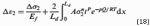
where Δσ 2 is the change in the average stress in the debond region over the time increment (Figure 22).
Figure 23 compares the predicted and experimental creep curves [117]. It also exemplifies the enhancement of creep deformations in the presence of matrix cracks when compared with the microcomposite without cracks. The same trends as for the uncracked microcomposites were predicted for the influence of fibre volume fraction on creep deformations. Comparison of creep models for microcomposites with CMR > 1and <1 (1300°C, 300 MPa, number of matrix cracks N = 5, shear stress = 10 MPa, Vf
= 0.3) [117]. Predicted deformations for a Hi–Nicalon/SiC minicomposite with a carbon interphase under a constant load of 110 N at high temperatures [125].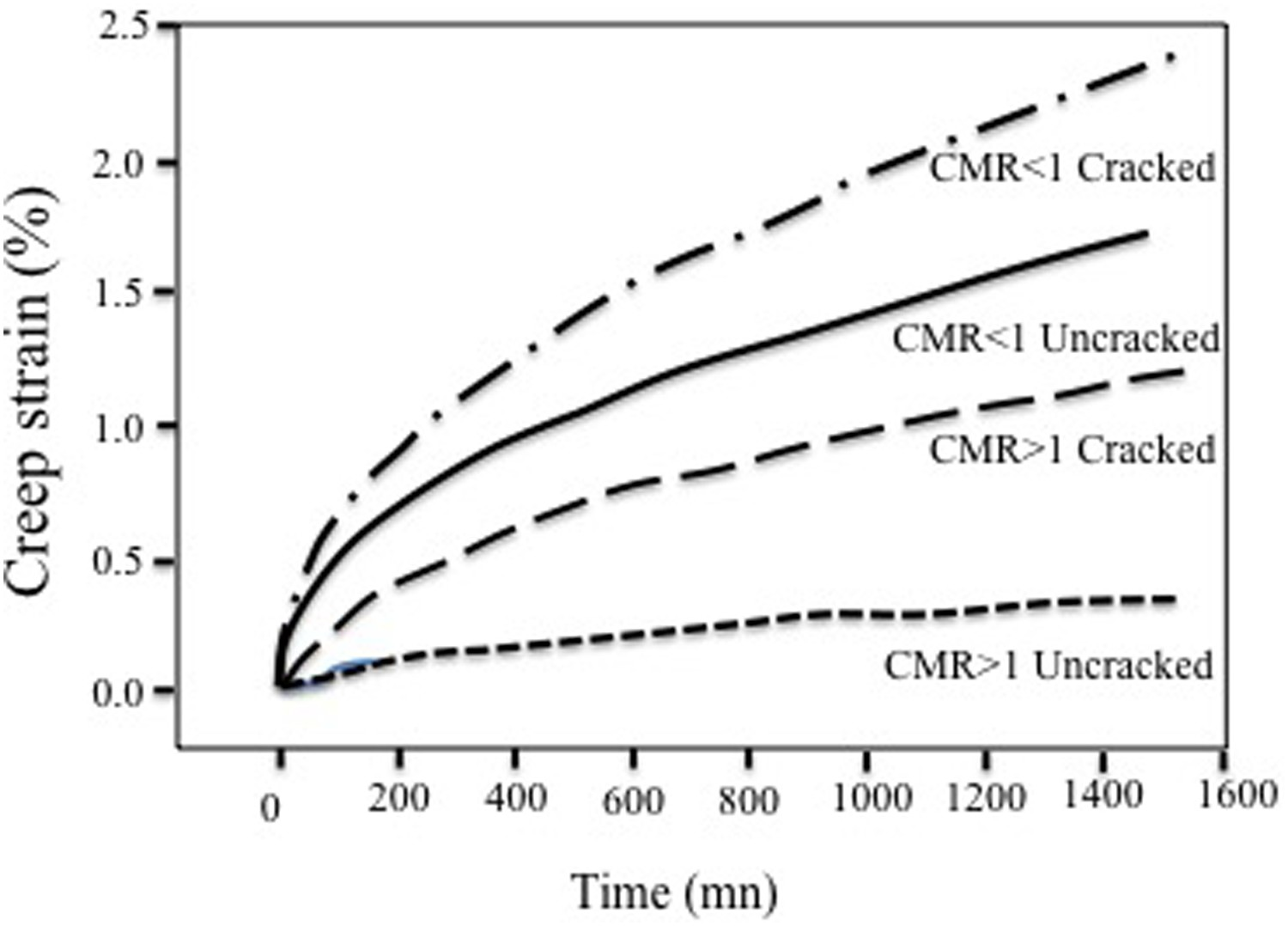
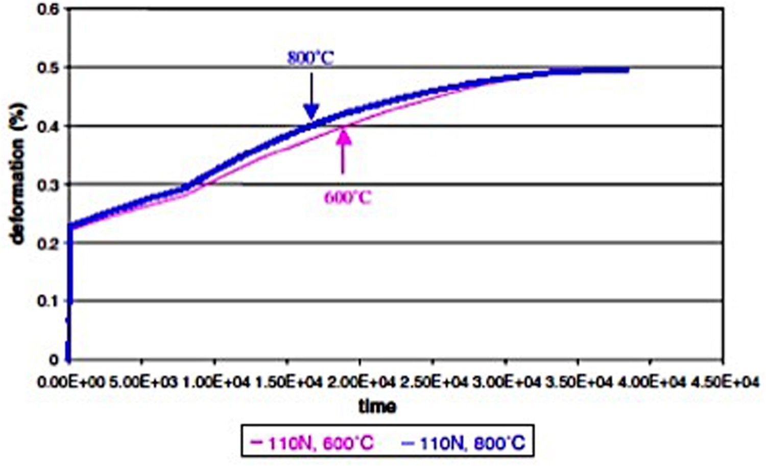
As shown by Figure 24, much larger deformations are predicted when CMR <1 (the creep rate of the matrix is taken to be larger than fibre creep rate) when compared to CMR >1. Again this result illustrates load sharing effect which enhances reloading of fibre during creep of the matrix.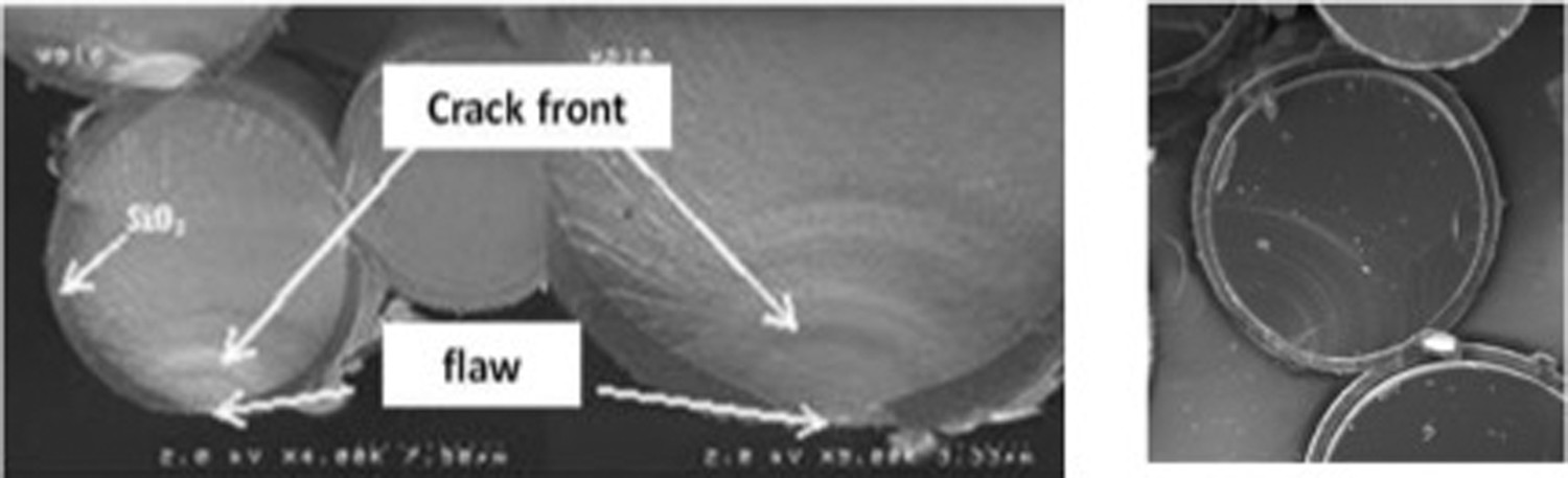
Additional predicted trends in the creep behaviour dependence on damage (interface debonding and matrix crack density) are discussed in Section ‘Preponderant factors’ on the influence of preponderant factors on creep behaviour.
Unidirectional composites with low fibre creep rate [119]
Park and Holmes [119] obtained similar trends in the evolution of load sharing and the effect of fibre volume fraction on creep behaviour of a unidirectional SiC (SCS-6) fibre-Si3N4 matrix composite with CMR <1: the creep rate of the SCS-6 SiC fibre is much slower than that of the hot-pressed Si3N4 matrix. The tensile creep curve of the composite was predicted on a geometric unit cell consisting of a fibre perfectly bonded to surrounding matrix using two-dimensional and three-dimensional finite element techniques. Stress levels below the matrix cracking stress were considered. The following power laws for creep rate at constant temperature were used [4,5,119]:
Creep of fibre:
Secondary creep of matrix:

where A, B, n′ and p′ are constants (−1 < p < 0). Values of constants for fibre and Si3N4 ceramic were determined by other authors [119]. These equations were implemented in the commercial finite element code ABAQUS. The predicted creep curves of the composite did not exhibit steady-state creep, but rather a continuously decreasing creep rate. This is the consequence of the dominance of primary fibre creep rate. The simultaneous addition of a transverse load while maintaining the axial load constant decreased the overall axial creep rate of the composite.
The SCS-6 fibres have a higher coefficient of thermal expansion than the Si3N4 matrix (5.5 10−6 C−1 vs. 3.2 10−6 C−1). Residual stresses develop upon cooling from the hot-pressing temperature of 1700°C, to the creep temperature of 1200°C. The consideration of residual thermal stresses caused a large decrease in the primary creep rate of the composite. This result illustrates the trend that was discussed above in Section ‘Microstructure/creep behavior relationship’.
In addition to the intrinsic recovery of the constituent phases, the analysis shows that recovery in fibre-reinforced CMCs is also driven by changes in the residual stresses in the fibre and matrix. The tensile residual stress which develops in the fibres upon unloading would cause in situ tensile creep of the fibres, whereas the compressive residual stress which develops in the matrix upon unloading leads to in situ compressive creep of the matrix. If the compressive creep rate of the matrix is greater than the tensile creep rate of the fibres, the composite will tend to contract back toward its original position. This contraction is accompanied by a redistribution of stress between the fibres and matrix based upon internal force equilibrium. Fair agreement was obtained between the predicted and experimental recovery curves.
Creep rate of 2D woven composite SiC/SiBC [34]
The model of creep rate proposed in [34] makes explicit the relationship between the respective creep rates of composite Nicalon/Si-B-C and of the reinforcing fibres. This simple model is aimed at evaluating the contributions of fibre creep and debonding to the overall creep behaviour of a 2D woven composite. It is based on the decomposition of the overall composite strain along fibre loading direction into components corresponding to the intact and the debonded parts in the presence of through the thickness transverse matrix cracks. The composite with a low weave amplitude behaves like an unidirectional composite when loaded in one fibre direction. As in previous section, the overall creep strain of the composite is the summation of the creep strains, εi , in the cracked and intact regions, i.e:
where ε
1 and ε
2 are the creep strain in the non-debonded region (denoted 1) and the debonded region (denoted 2), respectively. Region 2 includes the part of fibre subject to maximum stress and that part where the stress decreases steadily (Figure 22). In this latter portion the creep rate is given by the following equation: 

Log–log plots of creep rate versus time (Figure 16) indicate that, after a certain time t 0 (generally longer than 1 h), the composite creep rate data closely fit the power law [34,111]:
t 0 a time scale factor. t0 was taken to be 1 h. B(ε 0) is dependent on initial damage.
The Nicalon fibre exhibits only primary creep in most cases. Plots of creep rate data derived from creep curves reported in [48] for Nicalon fibres indicate the same trend and lead to the following creep power law at 1200°C for Nicalon fibres: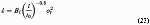 where σf
is the stress on fibre, Bf
is a constant.
where σf
is the stress on fibre, Bf
is a constant.
When contribution of the intact region to creep becomes negligible, composite creep rate is derived from Equation (23) as: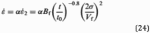 where α depends on the overall debond length and C.
Creep rates for Nicalon/SiC and Nicalon/Si–B–C (Figures 14 and 15) can be interpreted according to equation (25) derived from Equation (24): In the 2D woven SiC/Si-B-C composite, Equation (25) requires that matrix cracks are present in the longitudinal minicomposites, with a density such that the contribution of the intact region of composite is negligible. In the case of Figure 16, ε
0 = 0.8% had been applied to create the initial damage, which corresponds to the saturation of matrix cracking (section ‘Mechanical behavior under tensile loading’). At this stage, the matrix carries quite no load. Figure 16 shows that the slope of the
In the 2D woven SiC/Si-B-C composite, Equation (25) requires that matrix cracks are present in the longitudinal minicomposites, with a density such that the contribution of the intact region of composite is negligible. In the case of Figure 16, ε
0 = 0.8% had been applied to create the initial damage, which corresponds to the saturation of matrix cracking (section ‘Mechanical behavior under tensile loading’). At this stage, the matrix carries quite no load. Figure 16 shows that the slope of the 

Elastic fibre and matrix and environment-activated debonding [125]
A model of creep at temperatures < 1200°C was proposed for a SiC/SiC minicomposite specimen in the air [125]. The SiC matrix and fibres do not creep at these temperatures, while composite deformations are caused by the growth of debond cracks generated by matrix crack deflection. Furthermore, the model integrates the kinetics of matrix crack initiation during application of creep load, and fibre failures during composite creep.
Cracks in the matrix allow the ingress of oxygen which can cause the degradation of fibre/matrix interphases and fibre properties at high temperatures. In SiC/SiC composites with a pyrocarbon fibre/matrix interphase, the pyrocarbon interphase is consumed and the loads are progressively transferred to the fibres. Strain accumulation and fracture occur as a result of fibre reloading. Multiple cracking of the matrix and fibre failures are caused by flaws having a random distribution. They were described using a fracture statistics-based model [54]. The probability that a crack is induced by a flaw having random location and severity in an uncracked matrix volume element is given by the failure probability of this volume element. The density of probability of location of crack was assumed to be uniform. When the matrix experiences transverse cracking (perpendicular to fibres), minicomposite integrity is secured by fibres that bridge the matrix cracks. As a consequence, minicomposite deformations are dictated by the stress-state in the fibres. Fibre elongations ΔL are thus given by the following equation: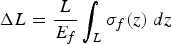
Thermally induced residual stresses were taken into account. As the interphase is consumed, the lengths of portions of fibres that carry the whole load increase and the stresses on fibres and matrix are changed accordingly (Figure 22). The fraction of consumed interphase β = l
0/Ld
increases: l
0 is the length of consumed interphase (it is assumed to be annular) near a matrix crack and Ld
is the initial size of debond crack. On the contrary, β is constant or decreases in the presence of crack healing. During interphase consumption, β increases to 1 in a first step, and then the debond length (l > Ld
) increases until the nearest debond crack is reached. At this stage, the fibres are completely debonded from the matrix and they carry the whole load. Owing to the lack of data on kinetics of oxidation reactions involved in interphase consumption, the following linear expressions were selected for the description of time-dependent interphase degradation: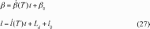
The predicted strain – time curve exhibits creep behaviour (Figure 25) with the three following domains that were expected: initial instantaneous deformation (0.23%) induced by the applied load; then a step of low rate deformation corresponding to the first stage of interphase degradation when β increases to 1; finally a second step of deformations corresponding to the second stage of interphase degradation when debond length (l > Ld
) increases up to complete debonding. At this final stage note that minicomposite strain is constant since the fibres do not creep. Ultimate failure did not occur because the applied load did not exceed tow strength.
Introducing creep of fibres and matrix, the model would allow prediction of kinetics of creep-induced cracking of the matrix and fibres, and prediction of composite creep behaviour. As minicomposite is a key entity in composite behaviour, the model can be useful for modelling creep of 2D or 3D structures.
Creep rupture for 2D composites
Matrix crack growth
Several authors investigated the creep rupture behaviour of composites with creeping fibres and elastic matrix, that is considered as the most deleterious because stress transfer from the fibres onto matrix can cause fracture [126,127]. The proposed models are based on the damage mechanism observed on 2D cross-ply Nicalon/CAS composite (section ‘Mechanical behavior under tensile loading’) [62]. It was assumed that the transverse cracks initiated in the 90° plies gradually extend in the 0° plies because of creep of the bridging fibres in the 0° plies that relaxes the bridging traction (Figure 7). The models concentrated on matrix crack growth considering that this is the major component of lifetime [see for instance 62,113,126–130]. Models for steady-state, constant velocity crack growth were developed for a composite with brittle elastic matrix containing creeping fibres [127]. Explicit equations of crack velocity have been proposed for fibres that exhibit linear elastic, steady-state creep. The authors considered that this behaviour has been found in SiC/SiC composites. However, this crack growth mechanism is not observed in 2D woven SiC/SiC [section ‘Mechanical behavior under tensile loading’, 56]. Furthermore, the Nicalon SiC fibres display generally primary creep only. The proposed equations for crack velocity do not include structural terms or parameters that would allow predictions for different microstructures as observed on textile composites with closely spaced fibres. No experimental validation has ben proposed. It was recognized that better appreciation of the model would be necessary [113] and that predictions required further developments to compare with experiments [128].
Monkman-Grant equation
The CMC rupture model proposed in [131] uses single fibre MG results to predict CMC rupture time for simple application conditions in which the matrix is cracked and uncracked and the fibres are able to act independently throughout CMC life. This model is based on the asumption that CMCs rupture occurs simutaneously with the time-dependent fracture of the fibre reinforcement.
If near-steady-state conditions are reached in the CMC life, it is proposed that the minimum CMC creep rate and the MG lines empirical equation could be used to predict CMC rupture time. The rupture model for CMC was consequently derived from the MG lines Equation (5) where tf
is the CMC rupture life, 
When the maximum applied load is low enough to initially inhibit through-thickness cracking of the matrix, it is proposed that the composite creep rate and the MG lines could then be used to predict which constituent will rupture first for a given SiC/SiC creep rate [131].
When the maximum applied load is high enough to initially cause through-thickness cracking of the matrix, thereby leaving the fibre bundles bridging the matrix cracks and exposed to the test environment, the stress on the bridging fibres can be directly calculated from the composite stress; so that composite rupture can be predicted based on the stress dependence for creep-rupture of the reinforcing fibres. The details of this simple rupture model and its verification data are presented in [131,132].
Safe use of the MG approach requires that the critical fibres in the composite that cause creep rupture are subjected to same conditions of stress and environment as the single fibres during creep tests. These requirements may be filled fortuitously since many parameters influence the creep behaviour of composites. Thus predictions of lifetimes successfully matched experimental results for woven Nextel 610/aluminosilicate composites [132], and Hi-Nicalon™/SiC minicomposites [133,134]. The Monkman-Grant method was inadequate for life predictions for enhanced SiC/SiC (Table 1) [37], Hi-Nicalon™/SiC minicomposites [133,134] and Nextel610/alumina–yttria composite [135]. In [37], the data showed a wide scatter, which indicates that variability in creep fracture stress also warrants consideration.
Influence of environment on composite creep
The environment influences the creep behaviour through effects on composite constituents including the matrix, and, the fibres and the interfaces in the presence of matrix cracks. Owing to applications of CMCs, oxidizing and irradiative atmospheres may enhance creep and rupture. Effects of irradiation will not be discussed in this paper. At low stresses below the matrix cracking stress, creep results from temperature-dependent phenomena (diffusional creep of constituents). At temperature beyond the stability temperature, the behaviour of thermally instable phases in fibres perturbs thermal creep. The stability temperature is around 1200°C for Nicalon fibre, 1400°C for Hi Nicalon and Hi Nicalon S fibre and 1800°C for Sylramic –iBN fibre. At higher stresses above the matrix cracking stress, the matrix cracks allow oxygen transit to the load carrying fibres, so that various deteriorating phenomena can take place in the debonded area: (1) fibre strength degradation or slow crack growth, (2) interface removal by oxidation, and (3) oxidation of fibres. The matrix cracking stress depends on various parameters including fibre stiffness, architecture, fibre volume fraction in the loading direction. It falls within the 60–100 MPa range for SiC/SiC composites [33,36,37,55]. It is generally not reported with high accuracy.
Influence of air
Comparison of creep properties determined in vacuum with those in air highlights the influence of air on creep behaviour. The nearly intrinsic time-dependent composite creep rupture properties were determined for the woven Sylramic-iBN fibre-reinforced melt-infiltrated SiC matrix composite at 1204°C in vacuum (10−5 Torr) and at stresses of 220 MPa that were larger than the matrix cracking stress [101]. They were found to be superior to the rupture properties of the same material tested under similar conditions in air. All the specimens tested in vacuum at 220 MPa stress level exceded the runout condition of 500 h with no failure, and the strain-rates were lower than the air test data by two orders of magnitude. It did not appear that a true steady-state strain rate has been reached.
It was shown by accident during creep tests on these woven Sylramic-iBN melt-infiltrated composites under the same creep conditions as above that oxygen concentration about 20 ppm was sufficient to favour oxidation and degrade failure times to values similar to those of air-tested composites [101]. This behaviour can be related to fibre oxidation. The mechanisms of strength degradation induced by fibre oxidation were discussed in Section ‘Creep rupture’.
Creep results at 1300°C and stresses below and above the matrix cracking stress for Hi-Nicalon™/SiC composite show lower strain rates and longer lifetimes in air when compared with those in argon [106]. A similar trend was reported for enhanced Nicalon/SiC composites (Table 1) under the same conditions [36]. This relation was attributed by the authors to the instability of Nicalon and Hi-Nicalon fibres at high temperature in argon [108]. Indeed, the Nicalon fibre is highly instable in argon as discussed in Section ‘Creep rupture’ and the enhanced matrix protects the fibres and the interfaces against oxidation. However, Hi Nicalon is claimed to exhibit high chemical stability, although a slight structural evolution was reported at high temperatures of both SiC and free carbon phases, from the pyrolysis temperatures in the range 1200–1400°C [48,73,135]. Furthermore, the carbon interphases are subject to oxidation in the presence of matrix cracks in Hi Nicalon/SiC composite in the air. By contrast, for the Nicalon/SiC composite, the creep resistance in air was found to be much lower than in argon, which was attributed to oxidation of carbon-based interphases and fibres in air [36]. The same phenomena and the same effects can be expected for the Hi Nicalon/SiC composite, which is at variance with the trend reported in [108]. Bodet noted inconsistencies in the time –to –failure values for Hi Nicalon fibres in argon [48]: 90% of the fibres tested in argon failed after a very short period of time. These premature failures might result from variations in the rate of active oxidation of SiC caused by variability in the amount of oxygen present in fibres [48]. Analysis of microstructural parameters and variability issues are required for sound comparison of creep behaviour for composite systems.
Oxidation-activated slow crack growth was observed on SiC-based fibres at temperatures in the range 500°C – 1300°C under a constant stress [91,94,97,136]. At temperatures >1300°C slow crack growth may occur also. The mechanism of subcritical crack growth is typified by Figure 26 that shows successive crack fronts detected in the fracture surfaces of Hi-Nicalon fibres after creep rupture of tows and 2D woven SiC/SiC in the air. A few authors considered first that a ‘pest’ problem operated in the temperature range 500–900°C, which affected the longevity of SiC/SiC composites. In fact, the origin of this premature failure was identified as oxygen-activated slow crack growth in fibres [94].
Influence of steam
The degradation of fibres and fibre coatings by oxidation generally occurs faster in the presence of moisture [138]. At 800°C, the presence of steam was shown to have a degrading effect on the creep lifetimes and rates of Hi-Nicalon S fibre tows [139]. In the air, the increase in temperature made the creep lifetimes of tows to decrease by approximately one order of magnitude, while in 100% steam environment, the increase in temperature from 800 to 1100°C made the creep lifetimes increase by at least one order of magnitude. Such an improvement in creep performance was attributed to the formation of a ‘protective’ silica scale. At 800°C in steam, the slow growth of surface defects is likely the dominant failure mechanism. At 1100°C in steam, a uniform silicon oxide layer (known to form on the surface of the SiC-based fibres at temperatures above 1000°C in oxidizing environments) decelerates the growth of surface defects thereby delaying fibre failure [139].
No data were produced in the literature on the creep behaviour of non-oxide composites under constant stress in the steam environment. The effect of steam on creep of SiC matrix composites was revealed by cyclic fatigue tests at 1300°C in air and steam [140]. Steam caused a significant degradation [140]
The presence of steam significantly degraded the performance of oxide–oxide CMCs under sustained loading (creep) as well as under low-frequency cyclic loading [58]. The degradation due to steam was minimal at lower temperatures (≤1000°C), but became dramatic as the temperature increased to 1200°C. Fractographic analysis revealed considerable matrix densification during prolonged exposures at elevated temperatures under load. The matrix densification due to additional sintering of the matrix was accelerated in the presence of steam. Matrix densification and subsequent loss of matrix porosity were the key mechanisms responsible for degradation of mechanical properties and performance at elevated temperature in steam. However, in oxide–oxide CMCs the porosity levels in the matrix (30–50%) are generally such that the fibres are also exposed to environmental attack. Thus fibre degradation is a possible source of composite degradation [58].
Preponderant factors
Influence of fibre type
Prominance of fibre property on creep is supported by several experimental data on composite creep. The minimum creep strain rate and the time to rupture of Nicalon/SiC composite at 1300°C are lower than those of Hi-Nicalon/SiC (Figures 12 and 13) [35,108]. This trend is consistent with the higher creep resistance of Hi-Nicalon fibres over Nicalon. A similar trend was observed at 1300°C in the air, on SiC, SiBN (Table 1) and Al2O3 matrix composites reinforced by Nicalon and Hi Nicalon fibres [35].
Tensile creep-rupture properties were evaluated in ambient air on 2D woven MI composites reinforced with different commercial SiC fibre types: at 1200°C for Tyranno ZMI, Tyranno SA, and Sylramic-iBN reinforced composites and at 1315°C for Tyranno SA, Hi Nicalon S and Sylramic- iBN reinforced composites [55,56]. The creep curves at 1200 and 1315°C are dominated by a decreasing strain rate, except for a few specimens that exhibited a region of increasing strain rate just prior to rupture. Figure 27 shows a few typical creep curves obtained under various stresses in the range 103–209 MPa. The creep performances were found commensurate with those of the reinforcing fibres. The composites ranked as follows in decreasing order of performance characterized by creep deformations, creep rupture stresses and times at the higher temperatures: first Sylramic, second Hi-Nicalon S, third Tyranno SA and finally Tyranno ZMI reinforced composite. Tensile creep total strain (elastic plus time-dependent) curves at 1200 and 1315°C in ambient air for MI SiC matrix composites reinforced with different fibre-types [55]: Tyranno ZMI (labelled ZMI-1), Tyranno SA-3 (labelled SA-1), Sylramic-iBN (labelled Syl-iBN-3) and Sylramic (labelled Syl-2). Also given are the creep stresses.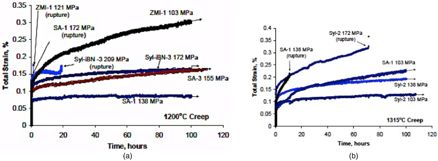
Similar trends were shown by tensile creep results obtained in the air at 1315°C on composites having SiC-based matrix produced by three different process routes (MI, CVI and PIP) [56] and reinforced by three different near-stoichiometric SiC fibre-types: Sylramic iBN, Hi Nicalon S and Tyranno SA. A true steady-state strain rate condition was never achieved for the composites tested in this study, which may be related to the strong primary creep component of the fibres. The iBN and Hi Nicalon S fibre-reinforcement enabled the most creep resistance compared to the SA3 fibre type at 1315°C. However, the type of matrix did have an effect on the composite creep and rupture lives due to load-sharing differences for the different matrix types and due to stoichiometry in the case of CVI SiC matrices. For the specific composites and specific test conditions used in this study, the dominant factors controlling tensile creep and rupture properties of the composites were the creep and rupture properties of the fibres [56]. More tensile creep data over wider stress, temperature and time ranges are needed in order to make a proper comparison of the composites. Models of composite creep and rupture would be efficient to take into account the various parameters.
Influence of matrix type
In argon at 1300°C, the enhanced Nicalon/SiC composite (Table 1) exhibits higher creep rates and longer lifetimes than the Nicalon/SiC composite (Figure 14(a)) [108]. This creep behaviour was attributed to the lower creep resistance of the enhanced SiC matrix [107], as a result of the addition of a glassy phase. The glassy phases would soften the matrix and may also promote the sliding of the interfaces between fibre and matrix as a lubricant at high temperature [108] which can increase creep deformation. However, creep crack growth path in the matrix of enhanced Nicalon/SiC is zigzag and discontinuous [36]. This is beneficial to resist crack growth compared to the straight crack path in the pure SiC matrix in Nicalon/SiC. Moreover, the high creep deformation reduces stress concentration at pores which are crack initiation sites [108]. Higher creep rates were also reported in [34] for Nicalon/Si–B–C when compared to Nicalon/SiC at 1200°C in argon for the same amount of initial matrix cracking damage.
In air, the creep rate is much lower and the time to rupture is much longer for the enhanced Nicalon/SiC composite (Table 1) when comparing with the Nicalon/SiC composite because of the protection of fibres by the enhanced SiC matrix against oxidation [108].
Wilshire et al. [35] compared the creep behaviour (strain rate versus stress) in air at 1300°C of SiC and oxidation resistant Al2O3 or SiBC (Table 1) reinforced with Nicalon or Hi Nicalon SiC fibres. Similar minimum strain rate values were recorded for the Al2O3 and SiBC matrix composites. They were lower than those obtained for the SiC matrix composites, all three materials being reinforced with comparable volume fractions of 0°/90° fibres.
The MI matrix was shown to be less creep resistant than an all-CVI–SiC matrix at 1315°C in air because of its reduced CVI–SiC content and the presence of low creep resistant Si at temperatures near its melting point (1410°C) [61]. Furthermore, Morscher detected an effect of the SiC matrix composition on creep and rupture lives of the composites with different matrix types discussed above in the previous section: MI Si-rich CVI SiC, stoichiometric CVI SiC and PIP SiC [56]. However, due to the fact that the different composites had different fibre volume fractions, a direct comparison of creep results did not allow the contribution of matrices to creep to be differentiated. This difficulty was overcome by considering creep rates normalized for fibre volume fraction. The normalized creep rates for CVI or MI SiC matrix composites at low stress were about the same, even though the MI matrices contained significant fractions of free Si (∼10–15% of total composite volume) and the Hi Nicalon S/stoichiometric CVI composite had a significantly lower fibre volume fraction. The creep strain rates were significantly higher for the PIP SiC matrix which was microcracked after processing unlike the MI and CVI matrices. Which suggests that significant load sharing was occurring during creep with the MI and CVI matrices that carry appreciable load. Creep-induced damage was negligible in the PIP matrix [56]. It was conjectured for MI and CVI matrix that microcracks initially formed upon loading (similar to fast fracture type tests in accord with the AE data); however, since the matrix is less creep resistant than the fibres, stresses were relaxed at the crack tip with time and matrix crack growth was halted until fibre breakage of oxidized fibres occurs in a matrix crack wake. More creep-induced cracks were observed in the stoichiometric CVI SiC matrix, that is the most creep resistant [56]. A very short rupture time was reported for the Sylramic-iBN/Si-rich CVI composite compared to the Sylramic-iBN/stoichiometric CVI composite (respectively 25 h and no failure after 250 h of creep at 138 MPa applied stress) [56]. However, for the Sylramic-iBN/stoichiometric CVI composite, fewer cracks were evident at 138 and 155 MPa compared to Sylramic-iBN/Si-rich CVI and no real through thickness cracks were formed except perhaps for the higher stress condition. Si-rich CVI SiC is known to be more creep-prone than stoichiometric or carbon-rich CVI SiC.
More tensile creep data are required to quantitatively characterize the creep behaviour of the various matrices and evaluate their contribution to composite creep behaviour. Except for stoichiometric CVD SiC (Section ‘Mechanisms of creep in ceramics’) intrinsic creep parameters are not available for MI Si-rich SiC and PIP SiC. They are required for a sound comparison of matrice creep behaviour and for prediction purposes.
Influence of interface/interphase
Fibre/matrix interphases play a significant role in the mechanical behaviour of CMCs by the control of load sharing between the matrix and the fibres. When the matrix is stiffer than the fibres, the load is transferred to the fibres in the vicinity of matrix cracks and associated debonded interface, which enhances fibre creep. The contribution of interface debonding to creep has been shown by Figure 23 [117] which compares experimental and predicted creep curves for cracked and uncracked Hi-Nicalon/SiC microcomposites.
Figure 28 shows the creep curves calculated for each region of the SiC/SiC microcomposite considered in the model of microcomposite creep discussed in Section ‘Models of creep deformation’ [117]. It is apparent that the largest contribution to the overall creep strain (55.6% at t = 24 h) comes from the debonded region of the microcomposite, despite its length being shorter than that of the intact section: 5.77 mm in the presence of 5 matrix cracks against 25 mm gauge length. Although the creep rate of the microcomposite is fastest at the crack opening, the small length of that region (a few microns) makes its contribution to the overall creep strain negligible. In the presence of a larger amount of transverse cracks or longer debond cracks, the contribution of the debonded and the crack opening regions is increased. Predicted creep curves at 1300°C in air at stress 300 MPa for each region of the matrix-cracked microcomposite normalized to its relative gauge length (Section ‘Creep testing’) [117], for a small number of matrix cracks (N = 5) and a low interface shear stress (10 MPa).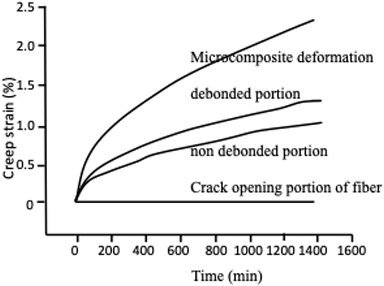
Similarly, the contribution of the debonded interface size to creep rate for a 2D woven SiC/Si–B–C (Table 1) composite is described by the model proposed by Carrère et al. [34]. Furthermore, experimental creep curves obtained on testspecimens with various initial matrix crack densities confirm the trend in contribution of the debonded interface size to creep rate (Figure 20) [34].
The interfacial behaviour during creep was investigated through interfacial friction stress measured from hysteresis loops. In [141] Hi-Nicalon/SiC microcomposites were creep tested in argon and in the air. The hysteresis loop width was found to increase slightly and interfacial shear stress decreased slightly during creep in argon. Which may be attributed to growth of the fibre/matrix interface crack, from the creep rate mismatch of microcomposite constituents. In the air during a long time creep tests, hysteresis loop widths closed significantly and the values of interfacial shear stress increased [141] which was attributed to oxidative closing of the matrix crack and/or the fibre/matrix interface. Lamouroux et al. [109] observed a weakening of the interface of an Al2O3 fibre-reinforced SiC composite during creep tests in argon, which they suggested was due to progressive fibre debonding. Evans et al. [113] measured hysteresis loops during creep tests in argon at 1200°C on a 2D SiC/SiC composite. The hysteresis loops became wider over time. The corresponding friction stress was found to be much lower after creep. This was attributed to either diminished residual stress at 1200°C or greater fibre compliance at this temperature [113].
Interfacial debonding by oxidation has only been observed in SiC/SiC with either pyrocarbon or BN as the fibre–matrix interface material [142]. Interface removal contributes to the stress relaxation of the fibre that occurs by creep. The model of creep behaviour driven by interface removal, at temperatures below the fibre creep regime threshold (T < 1200°C) has been discussed in section 4.1. Figure 25 shows the predicted creep curve with decreasing deformation rate at 600 and 800°C, in the absence of fibre and matrix creep.
It is clear that the significance of growth of the debonded interface is governed by interphase resistance to oxidation and to cracking. Interphase cracking is optimized with strengthened fibre/interphase bond obtained by fibre surface treatment [143]. In the presence of strengthened bonds, the debond size and, as a consequence, the associated portion of reloaded fibre are shorter [143] although the associated matrix crack density is increased [144]. The model of creep discussed in Section ‘Models of creep deformation’ predicts improvement in creep behaviour for SiC/SiC microcomposites with increasing interface friction stresses (the number of matrix cracks was assumed constant) (Figure 29). Overall, high values of interface friction stress may be preferable since composites with strengthened interfaces can carry higher applied stresses and exhibit higher toughness and stress at matrix crack saturation relative to the weak interface case [143]. Prediction of the effect of the interfacial shear stress on the creep behaviour of microcomposites in the presence of transverse through-thickness matrix cracks. The number of cracks was assumed to be constant (N = 5) [117].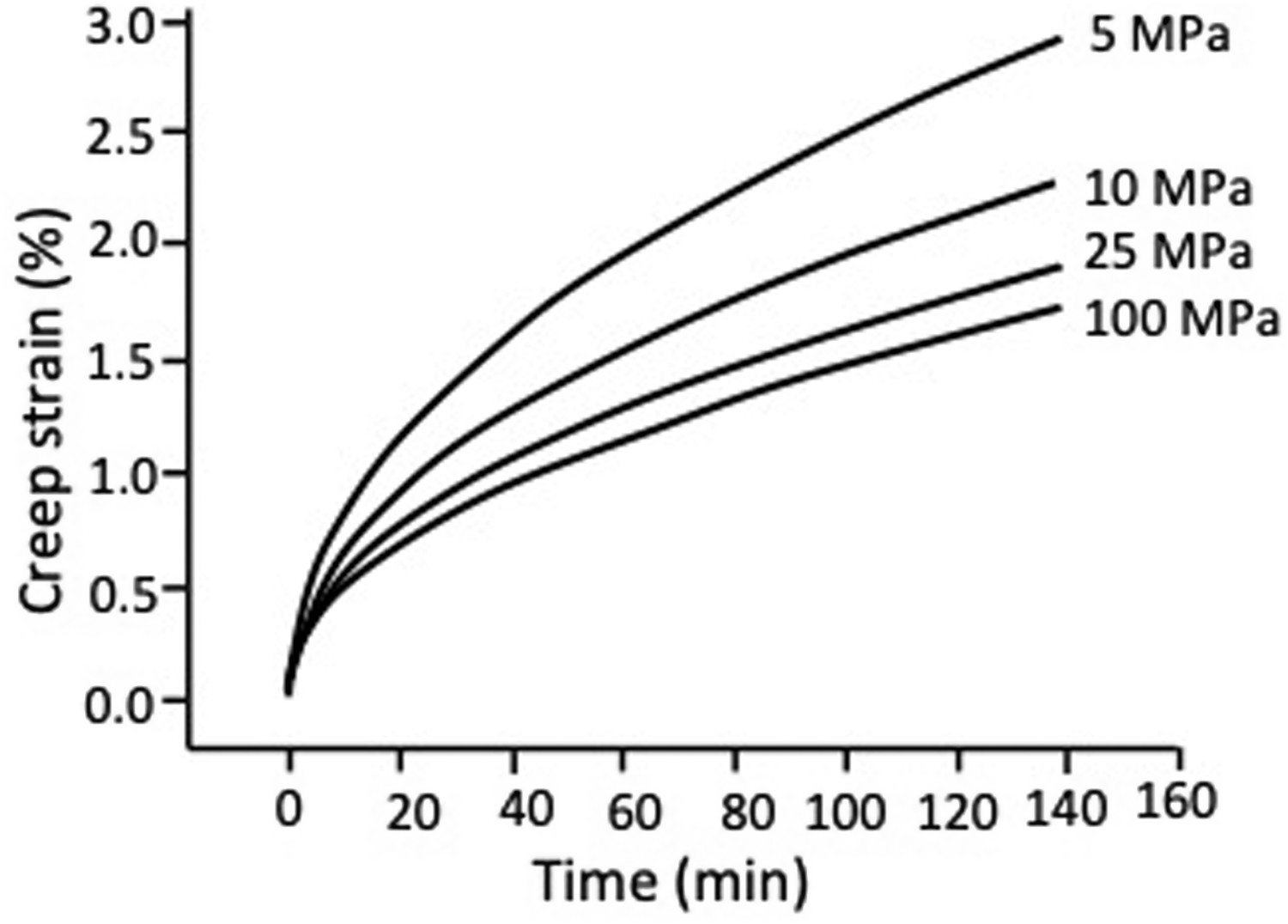
Structure, fibre preform
The influence of fibre preform on the creep behaviour is governed by the load sharing mode and, as a consequence, by the resulting initial damage mode that will dictate the stress state on constituents. To our knowledge, no big effort was put on this issue, and results that allow the comparison of creep behaviour of composites with different fibre preforms are not available. However, trends can be conjectured or anticipated for creep behaviour in the direction of loaded fibre, from the microstructure/mechanical behaviour relationships discussed in this paper, and considering the minicomposites oriented parallel and perpendicular to the loading direction for orthotropic structures.
A significant difference between damage modes in 2D woven SiC/SiC and 2D cross-ply SiC/CAS was reported in section ‘Mechanical behavior under tensile loading’. Then models anticipated that the creep rupture of 2D cross-ply composite was dictated by the propagation of matrix cracks (Section ‘Creep rupture for 2D composites’), whereas the creep behaviour of 2D woven SiC/SiC composite governed by the reinforcing fibres.
In unidirectional composites, the volume fraction of carrying fibres is quite twice the volume fraction in 2D composites, and three times the volume fraction in 3D composites with a balanced reinforcement. Then, a wide variety of preforms can be devised. Particular cases require an experimental or a numerical approach.
Conclusion
The creep behaviour of CMCs depends on many parameters including composite composition, structure and constituents, fibre/matrix interfaces and environment. Which leads to a wide variety of systems and test conditions so that comparisons based on a single macroscopical characteristic are uneasy. Beyond the general principles that govern the creep behaviour of the classes of CMCs, each particular case requires a specific investigation for the determination of creep curve.
The creep behaviour of CMCs is governed by the property mismatch between the fibre and the matrix, including thermoelastic and creep properties. It does not follow the laws of creep of monolithic ceramics. However, the laws for monolithic ceramics characterize properly the creep behaviour of fibre and matrix. As a consequence, the micro/macro relations-based models propose prediction of creep strain behaviour. Loading beyond matrix strength (which generally occurs at a low-stress level) generates matrix and interface cracks, which causes transfer of load onto the fibres oriented in the loading direction. In those composites with a low creep resistant matrix, the load is also transferred onto the fibre during creep. Thus, the creep behaviour of composites is controlled by the fibre. The new generation of Si-rich SiC matrices (such MI, Si-B-C, SiBC and enhanced SiC matrices) and the oxide matrices are less creep resistant than the stoichiometric SiC CVI matrix.
Most fibres and CMCs generally exhibit only primary creep, except in vacuum for the stoichiometric SiC-based fibres that exhibit two stages of primary and steady-state creep. The SiC-based fibres are more creep resistant than the oxide fibres, while the near-stochoimetric SiC fibres with low oxygen content are the most creep resistant ceramic fibres. Fibres of the second generation (Hi-Nicalon SiC) that contain less oxygen are superior to the first-generation fibres (Nicalon SiC) that decompose at high temperature in inert atmosphere like argon.
Air and steam environments affect CMC creep behaviour in the presence of matrix cracks, and argon is not an inert gas for Nicalon or Hi Nicalon reinforcement. Composites with a crack healing matrix (like the so-called enhanced SiC/SiC, SiC/SiBC and SiC/Si–B–C composites; Table 1) show lower strain rates and longer lifetimes in the air when compared with composites with a standard SiC matrix in air or argon environment.
Several issues are still open. The intrinsic characteristics of thermal creep are not available for most ceramic matrices, fibres and CMCs. Laws of fibre strength degradation under stress were not established, except for slow crack growth at temperatures <1300°C in air. More creep tests under wider interval of creep conditions are required for a proper description of creep behaviour of composites and consideration of variability issues. Robust models that account for the influence of a variety of preponderant parameters are needed. They would involve multiscale models that recognize the key entities (microcomposites and minicomposites). More complex multiaxial loading requires numerical analyses based on the fundamental principles of interactions of creep behaviour of fibre and matrix.
Footnotes
Disclosure statement
No potential conflict of interest was reported by the author.
1
Details on the respective composition and properties of these matrices are unavailable. The composition is proprietary. Therefore, the terms used by authors (Si–B–C, or SiBC, or enhanced SiC matrix) will be kept, in order to differentiate them.