
Abstract
Additive Manufacturing (AM) has the potential to completely reshape the manufacturing space by removing the geometrical constraints of commercial manufacturing and reducing component lead time, especially for large-scale parts. Coupling robotic systems with direct energy deposition (DED) additive manufacturing techniques allow for support-free printing of parts where part sizes are scalable from sub-metre to multi-metre sizes. This paper offers a holistic review of large-scale robotic additive manufacturing, beginning with an introduction to AM, followed by different DED techniques, the compatible materials and their typical as-built microstructures. Next, the multitude of robotic build platforms that extend the deposition from the standard 2.5 degrees of freedom (DOF) to 6 and 8 DOF is discussed. With this context, the decomposition and slicing of the computerized model will be described, and the challenges of planning the deposition trajectory will be discussed. The different modalities to monitor and control the deposition in an attempt to meet the geometrical and performance specifications are outlined and discussed. A wide range of metals and alloys have been reported and evaluated for large-scale AM parts. These include steels, Ti, Al, Mg, Cu, Ni, Co–Cr and W alloys. Different post-processing steps, including heat treatments, are discussed, along with their microstructures. This paper finally addresses the authors' perspective on the future of the field and the largest knowledge gaps that need to be filled before the commercial implementation of robotic AM.
Introduction
Additive Manufacturing (AM), also known as 3D printing, uses computer-aided design (CAD) to build objects layer by layer [1]. This contrasts a significant portion of traditional manufacturing, which uses casting, sintering or removing unwanted material from an ingot using machining[2]. AM is still in its infancy, but the projected possibilities will drastically change the manufacturing space. One of the proven advantages of AM compared to conventional manufacturing is the lack of shape constraints on components. This allows for complex geometries to be constructed, where conventional manufacturing would require the joining of multiple pieces to create the same part [3]. Geometrical freedom has the potential to reduce component lead time, cost (fabrication of cast not needed, lower energy consumption, material cost), material waste, energy usage, carbon footprint, and drastically reduce the need for post-processing [4].
The industrial applications of AM range from aerospace to the energy sector to healthcare. The ultimate goal is to have on-site access to this technology, eliminating the need for stockpiles of replacement parts. Although AM research is currently also conducted in the construction sector [5], the focus of this paper is on metal AM. According to the ISO standard 17296-2, seven process categories currently exist, including vat photopolymerization, material jetting, binder jetting, powder bed fusion, material extrusion, direct energy deposition and sheet lamination [6]. A large portion of the research and commercial development of metal AM systems has been on powder bed fusion (PBF) [7–9]. In these machines, a laser is scanned over a fine layer of powder, fusing it together. The build substrate drops down according to the layer thickness, and the powder is redistributed using a roller or scraper, and the laser fuses the newly distributed powder to the previously deposited material. This process repeats until the part is complete. These platforms are intrinsically limited to 2.5 Degrees of Freedom (DOF), where each layer is printed on a two-dimensional plane [10, 11]. A limitation of 2.5 DOF is the need for support structures on overhanging features of more than 30–40

There is garnering interest in expanding the DOF of AM systems to allow for the manipulation of the part in-situ. This would eliminate the need for support structures [16–19]. The increase in DOF is achieved via the integration of robotic manipulators and positioners (see Figure 1). The manipulators can then house various direct energy deposition (DED) modalities such as gas metal arc welding (GMAW), gas tungsten arc welding (GTAW), laser-based direct energy deposition (LDED) and plasma arc transfer welding (PTAW), enabling multi-directional deposition [20–23]. A depiction of this is shown in Figure 1, where the part's orientation has changed to compensate for the overhanging angle. Combining these systems can theoretically eliminate the size restrictions of the parts that can be built using AM. This sparks considerable interest from not only the energy sector but shipping, mining and any industry that requires large-scale parts. The complexity of these parts is not due to stringent geometrical tolerances but is restricted by the sheer size of the components [24]. One rendition of this is the combination of additive and subtractive manufacturing, which takes the free formability of AM and combines it with the surface finish capabilities of machining. This is known as hybrid manufacturing [25, 26]. Researchers have been developing path planning programs for these types of systems, but the combination of the two processes drastically increases cost compared to pure AM processes because of longer fabrication times, and would not be suitable for large scale applications in the current state [27–33]. An example of a large-scale robotic AM fabrication platform using a wire and arc welding system for metal deposition.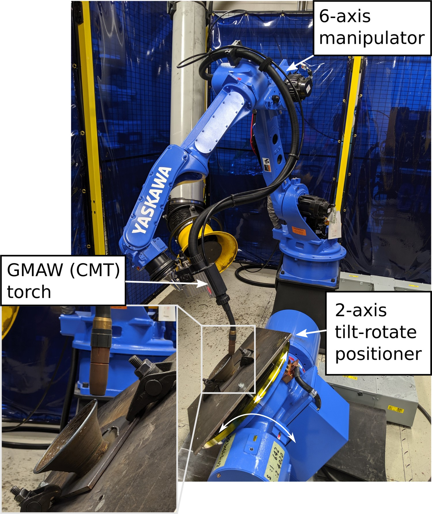
The current objective of large-scale additive manufacturing is to use 7- and 8-axis robotic serial manipulator systems, and in-situ monitoring and control systems, to eliminate the need for subtractive measures and supporting structures [16, 18, 34–37]. The different technologies to achieve this have been implemented in various other applications but have not yet been integrated into a holistic process. Various companies have implemented commercial large-scale robotic AM, including: Relativity Space [38], MX3D [39], MER corporation, AML3D [40], and AMFG [41]. Two examples of large-scale components fabricated via robotic AM are shown in Figure 2. However, their methodologies have not been published and will not be considered in this work.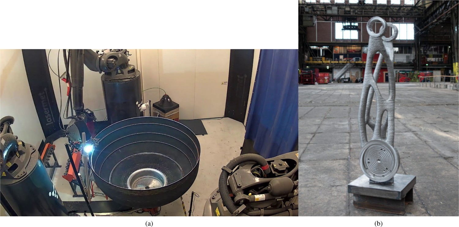
Some of the existing and under development codes and standards pertaining to additive manufacturing. It should be noted that this is not an exhaustive list, but provides insight on the magnitude and breadth of standards being developed for DED AM.
This paper aims to identify the state-of-the-art technologies and how they relate to large-scale additive manufacturing and the interdisciplinary engineering challenges that this process encompasses. For this work, large-scale AM constitutes the ability to fabricate a part with a volume of 
The structure of this paper is as follows. The first sections will discuss various DED technologies to provide context to the complexity of the manufacturing systems. This will transition to the different stages of the AM workflow, shown in Figure 3, where stage 1 is pre-process planning, stage 2 is printing/deposition and stage 3 is post-processing. Stage 1 encompasses the decomposition of the part into sub-volumes, the cross-sectional slicing of said subvolumes, and the conversion of the sliced layers to a tool path and deposition strategy based on the deposition system being used. Although not directly addressed by the publications, the thermophysical properties, and the thermal properties will dictate the optimal deposition strategy to reduce residual stresses, deposition defects and microstructural anisotropy. This will vary depending on the material being deposited. Stage 2 corresponds to the monitoring and control of the deposition and extracting the valuable information from the various sensors, which are used to adjust the operating parameters of the system in situ. The development of this stage is critical to automating large-scale AM, making it commercially viable for on-site manufacturing by non-specialized personnel and potentially eliminating the need for stage 3. An important consideration is optimizing the thermal cycles to achieve the microstructure and corresponding mechanical properties required for the parts application. Stage 3 deals with the post-processing required for the part to meet metallurgical, geometrical and performance specifications required for in-service use. Each stage corresponds to separate chronological sections of this paper, where each constituent of that stage and its current state in regards to large-scale additive manufacturing will be discussed. This paper will conclude with the author's perspectives on the challenges that must be overcome to make large-scale AM, a commercially viable manufacturing option. The robotic large-scale metal AM process workflow.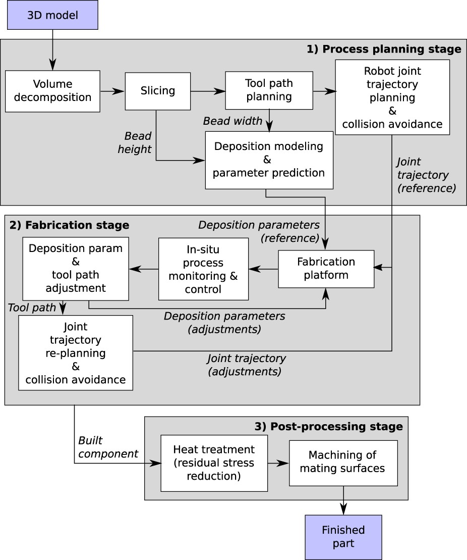
The main metal deposition technologies found in large-scale AM are: Gas Metal Arc Welding (GMAW), Gas Tungsten Arc Welding (GTAW), Plasma Transferred Arc Welding (PTAW) and Laser-based direct energy deposition (LDED). A detailed illustration of these deposition technologies can be seen in Figure 4. These systems are most readily used due to the ease of integration with the current multi-axis systems or have previously been used on robotic systems in industries such as automotive manufacturing. One advantageous characteristic with these modalities is higher heat inputs, which enables higher deposition rates, accelerating the printing process. This is an essential factor for large-scale AM to reduce the lead time for part production. However, one caveat to higher heat input is higher thermal stresses and heat accumulation, resulting in large amounts of material undergoing complex thermal cycling and anisotropic microstructures [44–46]. Furthermore, the material feedstock for DED is typically wire, or powder-based, which offers the ability to alter both deposition rate and composition based on the mechanical specifications of that localized area [47–49]. Changing the composition could range from going from one material to another or changing the volume loading of reinforcement particles in a metal matrix composite. This functional gradient could allow for customized spatial mechanical properties of areas that require them while also reducing the material cost of manufacturing. In this section, the following technologies will be discussed: GMAW, PTAW and LDED. This will include the fundamentals of the operation and the mechanisms of deposition. This will be followed by the common material feedstocks and the as-deposited microstructures that are typically found. The range of processing parameters for each deposition technology based on whether the feedstock is powder or wire are shown in Table 2 and Table 3, respectively. The values listed in the tables are the minima and maxima for each parameter recorded in the literature. Additionally, authors whose parameters fall within the range are given. It should be noted that lamination AM and cold-spray AM are also capable of creating large-scale parts. Lamination AM is currently not compatible with multi-axis robotic systems, eliminating it from consideration. Cold-spray AM is compatible with robotic systems but lacks the ability to create complex parts without special equipment, and significant post-processing [167–169]. Thus it was not considered in this work. Various AM DED technologies: (a) GMAW, (b) PTAW and (c) LDED.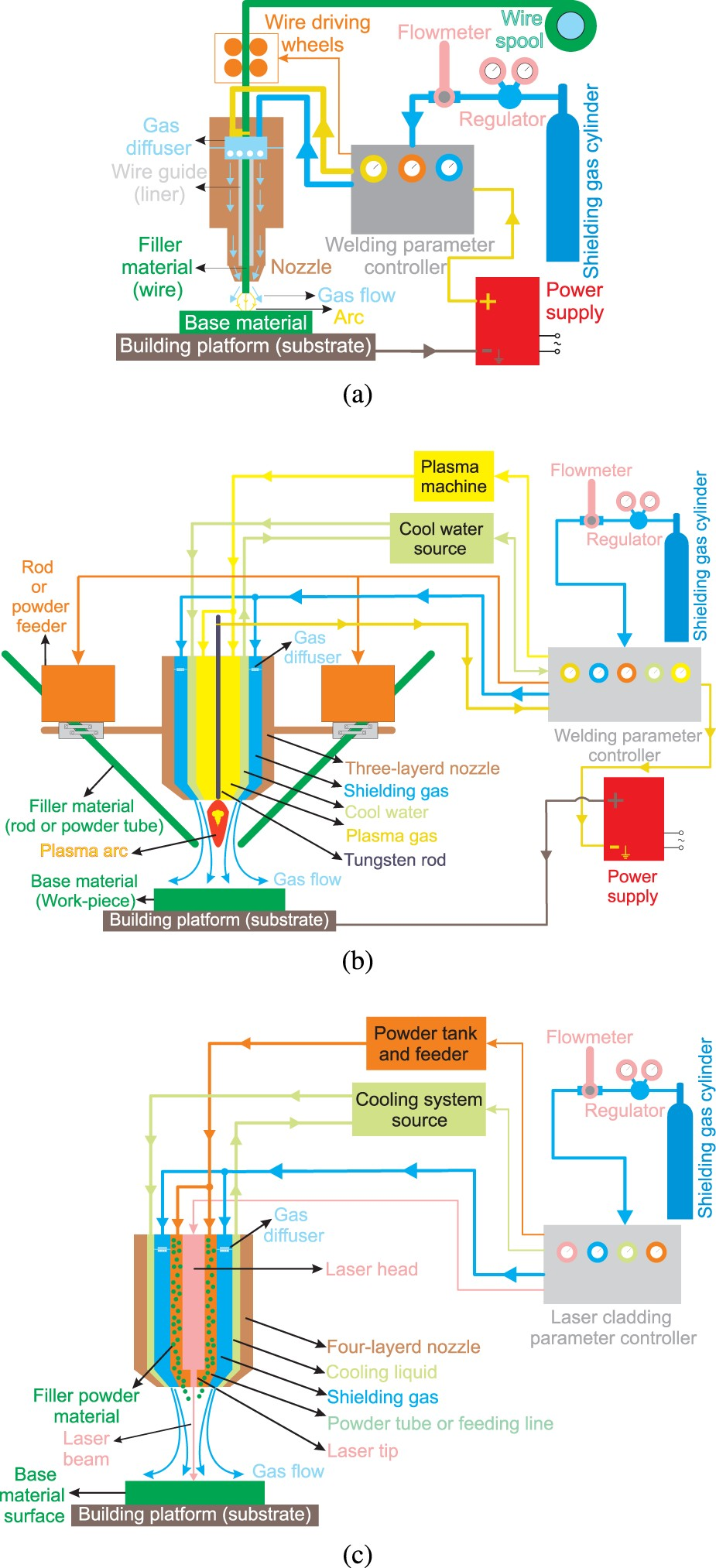


A listing of various powder fed deposition technologies and associated parameter based on the material being deposited. The values listed provide the maximum and minimum for each parameter and the authors who's parameters fall within those ranges.
A listing of various powder fed deposition technologies and associated parameter based on the material being deposited. The values listed provide the maximum and minimum for each parameter and the authors who's parameters fall within those ranges.


A listing of various wire fed deposition technologies and associated parameter based on the material being deposited. The values listed provide the maximum and minimum for each parameter and the authors who's parameters fall within those ranges.


Three traditional transfer modes are commonly used with the GMAW process, which are: spray, globular and short circuiting [173]. Cold metal transfer (CMT) is a modified subsidiary of short circuiting, where the mechanical movement of the wire electrode is synchronized with the electrical control parameters [111]. Instead of increasing the current during the short circuit phase, the current is dropped, extinguishing the arc and limiting the amount of thermal energy transferred to the deposit [174]. The electrode is then retracted, pinching the molten material, depositing it into the melt pool. The current is then increased to reignite the arc and the process repeats [175]. The decrease in thermal energy transfer reduces the heat accumulation in multi-layer deposits, which can be characterized by the finer grain structures when compared to continuous welding techniques [111, 176]. This can be seen in Figure 5 [177], where the lower heat input and heat accumulation is characterized by the finer grain structure. Furthermore, the pulsing of the arc has been shown to sever dendrite arms, increasing the heterogeneous nucleation sites, further refining the microstructure [115, 132]. It also drastically reduces the dilution of previously deposited material, reducing the amount of material being melted with each pass and possibly reducing the number of thermal cycles [175, 178]. Thus these reasons make CMT the most viable option for wire and arc additive manufacturing (WAAM). It should be noted that although there is a reduction in heat input and thermal cycles compared to continuous welding, WAAM deposits still suffer from heat accumulation, cracking, porosity, delamination and anisotropic microstructures [179]. The first study of using GMAW for AM was conducted by Dickens et al., who tried to expand the realm of 3D welding from large pressure vessels, to more complex geometries [180]. Microstructure variations from the WAAM deposition of AWS ER70S-6 where (a) shows the finer grain structure of a deposit with low heat input and low amounts of heat accumulation and (b) show the grain structure with high heat input and large amount of heat accumulation [177].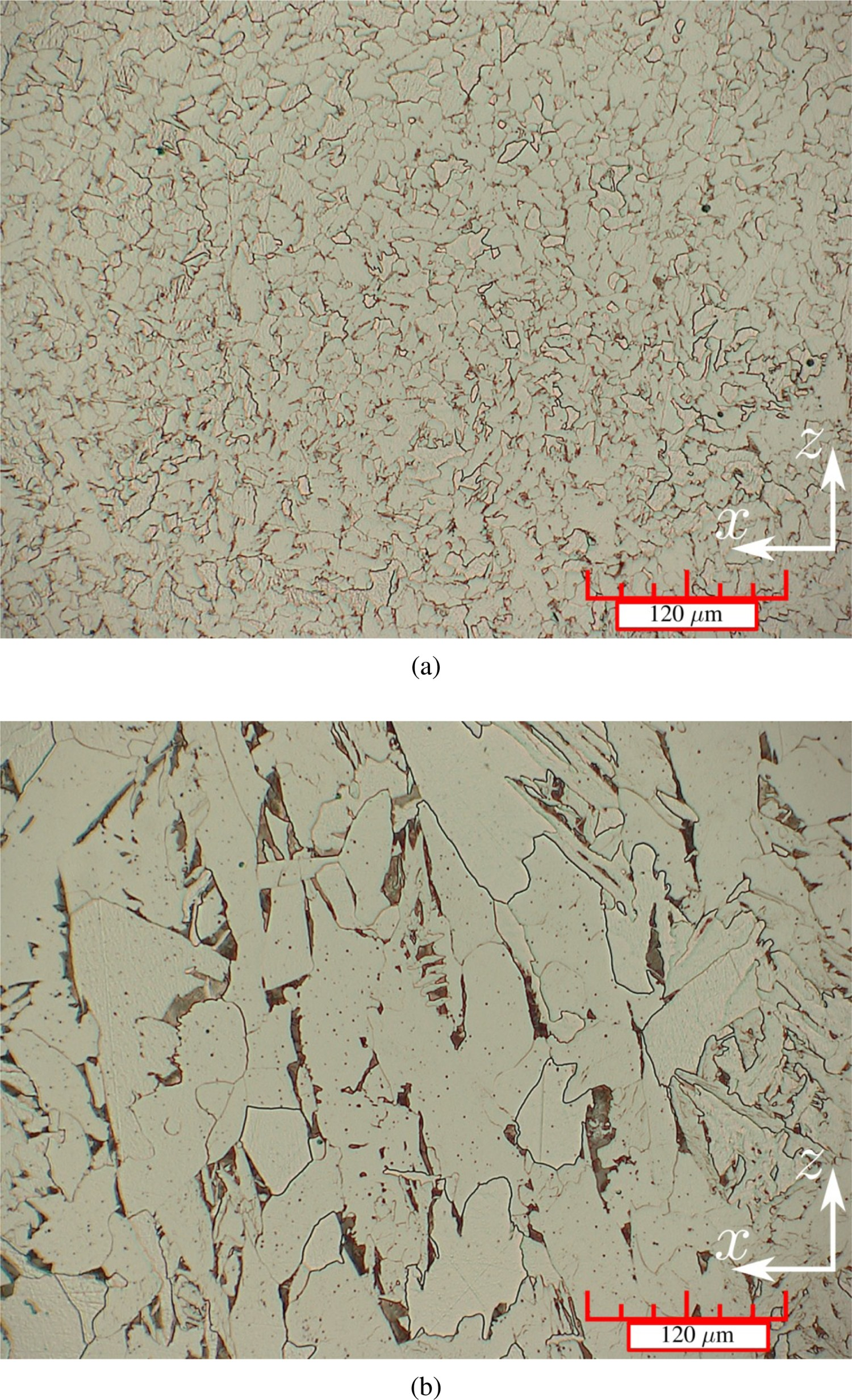
Gas Tungsten Arc Welding is similar to the GMAW process, but the arc is struck between a non-consumable tungsten electrode and the workpiece. A filler metal can be fed manually or mechanically into the arc, where it melts and is deposited onto the substrate. Multiple filler metals can be fed simultaneously to increase the deposition rate and allow for the customization of the material being deposited. Inert shielding gasses (typically Ar or He) protect the melt from oxidation while also affecting weld bead geometry. The polarity of the system can be altered from DC to AC if the material being deposited is prone to forming passive films [181]. The microstructure and mechanical properties of AM deposits are highly dependent on the material feeding orientation [182, 183]. Some of the materials that have been deposited include: TiAl [184], Fe–FeAl functionally graded material [185], FeAl [186], Ti64 [94, 133, 187, 188], Al [189] and Ni alloys [190].
GMAW and GTAW offer a cost-effective means of AM, with techniques that are already common industrial practice. The ease of integration with robotic control and gantry systems, coupled with the high deposition rates, makes these technologies enticing for large-scale additive manufacturing [191]. However, some complications reside when using a welding heat source for AM. Distortion and residual stresses are common side effects of the concentrated heat flux generated from an arc [192]. Inconsistent bead geometries can lead to poor surface finish and dimensional accuracy [193]. Research has predominately been on GMAW, which is speculated to be due to the added complexity of integrating a wire feeding system with the robotic system. Ensuring the feeding angle is constant during deposition would increase the difficulty of path planning and building strategies. The continuous heat input experienced during GTAW could cause increased heat accumulation, resulting in manufacturing defects such as the slumping of different features. Furthermore, GMAW's ability to easily strike and extinguish an arc increase the thermal control during the build by extinguishing the arc after each pass to allow for the part to cool. The tungsten electrode in GTAW also requires frequent sharpening to maintain arc characteristics, decreasing the production rate of large-scale parts.
Plasma transferred arc utilizes a non-consumable tungsten electrode, similar to that seen in GTAW; however, there are some stark differences between the processes as can be viewed in Figure 4(b). Generally, there are two inert gas inlets: the plasma and shielding gas. The gases used in this process (such as Ar) are chosen due to their low ionization potential, making it easier to strike an arc between the electrode and the substrate. The flow of the plasma gas allows the arc to be self-sustaining, while the shielding gas protects the melt from the surrounding environment [194]. The plasma is constricted by a nozzle, changing the arc shape from the traditional bell shape to columnar, increasing the energy density [195]. The feeding material can either be wire, or powdered materials, allowing for a large degree of compositions and functionally graded parts. The deposition rate is the highest of the welding techniques are 33–166 g min
Laser-based direct energy deposition
Laser-based DED techniques share the basic principles with the aforementioned plasma-based methods, where the main difference lies in the energy source. For laser systems, a series of lenses are used to focus a laser beam to melt the desired material [205]. The laser source can vary depending on the particular application. 


Materials
In all AM techniques, the feedstock metals can be in the form of wire or micron-size powder. Powder metals are typically much more expensive than their wire counterparts, but offers material compositions that are not able to be drawn into a wire. An example of this are higher reinforcement loaded MMC's and intermetallics, where the inherent brittle nature of these materials make it unsuitable for wire applications [212]. However, the deposition efficiency of wire fed systems is beyond what is possible with powder [213]. Moreover, the storage of metal powders requires significantly more safety precaution than that of metal wires and the higher surface area to volume ratio makes them more susceptible to oxidation [214]. The quality of the feedstock is of utmost importance, as porosity in the feedstock stock powders has been shown to drastically increase the porosity of the printed part [91]. Poor surface quality and diameter variances of wire feedstock can trap moisture and hydrocarbon residue during the deposition process, resulting in porosity in the final deposit [215–218]. This section of the report will outline the common materials and the as-built microstructures found in the above-mentioned AM techniques, as shown in Table 2 and Table 3. The variation in mechanical properties of AM deposits will be compared to conventional manufacturing where applicable, and the microstructural justification for differences will be discussed. The order of materials is as follows: first steels will be discussed, followed by titanium, aluminium, nickel, magnesium, copper, cobalt–chrome and tungsten alloys. It should be noted that there has been work done on energetic materials, typically in the form of metal–polymer composites. However, the printing modalities for these materials are currently limited to those suited for polymer materials and were deemed out of the scope of this paper. The topics discussed in Section 3 and Section 4 can be applied to the deposition of energetic materials, specifically those that utilize a deposition nozzle like direct writing, fused deposition modelling and photopolymerization [219].
Steels
Steels are extensively used in various industrial sectors due to their high strength, good toughness and low cost. There has been extensive work on the AM of steels, especially with WAAM. Some honourable mentions include: ER70S-6 [98, 102, 103, 220], 304 SS [98, 99, 129, 221], 308L SS [104, 105, 130, 148] and AISI 420 SS [106].
In the case of 316L austenitic stainless steel, LDED fabricated parts were reported to exhibit a higher hardness, yield stress and tensile strength with lower elongation than their wrought counterparts [55]. These differences in mechanical properties were attributed to the finer cellular arm spacing of the LDED manufactured steel compared with the wrought one [55]. The grain structure of LDED fabricated 316L stainless steel is highly dependent on process parameters, where grains become coarser by increasing power density and decreasing scan speed [50]. The 316L stainless steel fabricated by GMAW-AM was reported to have greater hardness and UTS, but a lower elongation than the wrought steel [107]. Microstructure and mechanical properties of the GMAW-AM fabricated 316L stainless steel depend on arc mode. A finer grain size (and consequently a higher strength and hardness) is achieved when spray transfer mode is replaced with short-circuiting transfer mode [107]. This is explained by the lower heat input of the short-circuiting than the spray transfer mode, which leads to a faster cooling rate [107].
Another common steel grade in AM is 17-4 PH martensitic stainless steel. However, the majority of the work has been on powder bed methods [222–227], as opposed to DED [51, 91, 108, 172, 228, 229]. High cooling rates associated with the selected AM processes limit transformation of δ-ferrite to γ-austenite at high temperatures so that some amounts of δ-ferrite remain at room temperature. AM fabricated 17-4 PH stainless steels commonly exhibit a dendritic microstructure with interdendritic δ-ferrite in a lath martensitic matrix [51, 108, 172]. It has been shown that proper shielding must be implemented with PTA-AM of 17-4 to prevent interlayer oxidation during fabrication[91]. Caballero et al.[108] fabricated 17-4 PH stainless steel from a wire feedstock using a GMAW-AM technique. They reported that decreasing the heat input to the system increased the solidification rate and subsequently the amount of retained austenite in the as-built microstructure. Moreover, the as-built parts had lower yield stress and UTS than wrought 17-4 PH stainless steel. However, exposure to a solution and aging heat treatment increased their yield stress and UTS significantly to be comparable with those of the wrought alloy [108]. Adeyemi et al.[51] investigated the influence of laser power on the microstructure of LDED fabricated 17-4 PH stainless steel. They observed a coarse microstructure at a high laser power due to high laser intensity and consequently slower cooling rate [51]. In another study, Martina et al.[172] fabricated walls from 17-4 PH stainless steel wires using a tandem GMAW torch. They reported a drop in strength and hardness of the deposited walls with an increase in wire feed speed, which was attributed to an increase in grain size [172].
Anisotropy of both microstructure and mechanical properties is significant in DED fabricated steel parts. The microstructural grains and dendrites are preferentially oriented along the build direction with the highest thermal gradient [56]. Thus, for the vertical orientation parts in which the build direction is parallel to the deformation direction, fewer grain boundaries exist compared to the horizontal orientation parts in which the tensile direction is perpendicular to the build direction. Since grain boundaries act as barriers to dislocation motion during the deformation, less dislocation accumulation occurs in the vertical orientation parts than horizontal orientation parts. Consequently, the vertical orientation parts exhibit a lower tensile strength but a higher elongation than the horizontal orientation parts. This anisotropy of the mechanical properties has been reported for the LDED fabricated 304L stainless steel [52], WAAM fabricated 304L stainless steel [129], LDED fabricated 316L stainless steels [52, 53, 56], WAAM fabricated 316L stainless steel [109], WAAM fabricated H13 tool steel [100] and WAAM fabricated 17-4 PH stainless steel [108].
For example, the influence of part orientation on the tensile behaviour of WAAM fabricated 304L stainless steel is depicted in Figure 6 [129]. The vertical orientation parts (L1, L2 and L3) exhibited an average yield stress, UTS and elongation of 231 MPa, 622 MPa and 88.1%, respectively [129]. Horizontal orientation parts (T1, T2 and T3), however, were reported to have an average yield stress, UTS, and elongation of 235 MPa, 678 MPa and 55.6%, respectively [129]. For most industrial applications, fabricated parts need to exhibit uniform mechanical properties. Thus the anisotropy of the mechanical properties in the AM steel parts is a challenge. Several studies were conducted to solve this issue. Wu et al. [109] investigated the anisotropy of the mechanical properties in 316L stainless steel components fabricated by speed cold welding AM. They observed a pronounced reduction in the anisotropy by decreasing scan speed and increasing cooling time. This was attributed to the cooling rate reduction [109]. Wang et al. [100] reported that the mechanical properties of the WAAM fabricated H13 steel became isotropic as a consequence of annealing at 830 C for 4 h. In another study, Fu et al. [230] eliminated anisotropy of mechanical properties in a bainitic steel using a combination of WAAM and micro-rolling. This hybrid technique's fully equiaxed grain structure resulted in the isotropic mechanical properties [230]. Tensile plots of WAAM fabricated 304L stainless steel for vertical orientation (L1, L2 and L3) and horizontal orientation (T1, T2 and T3) [129].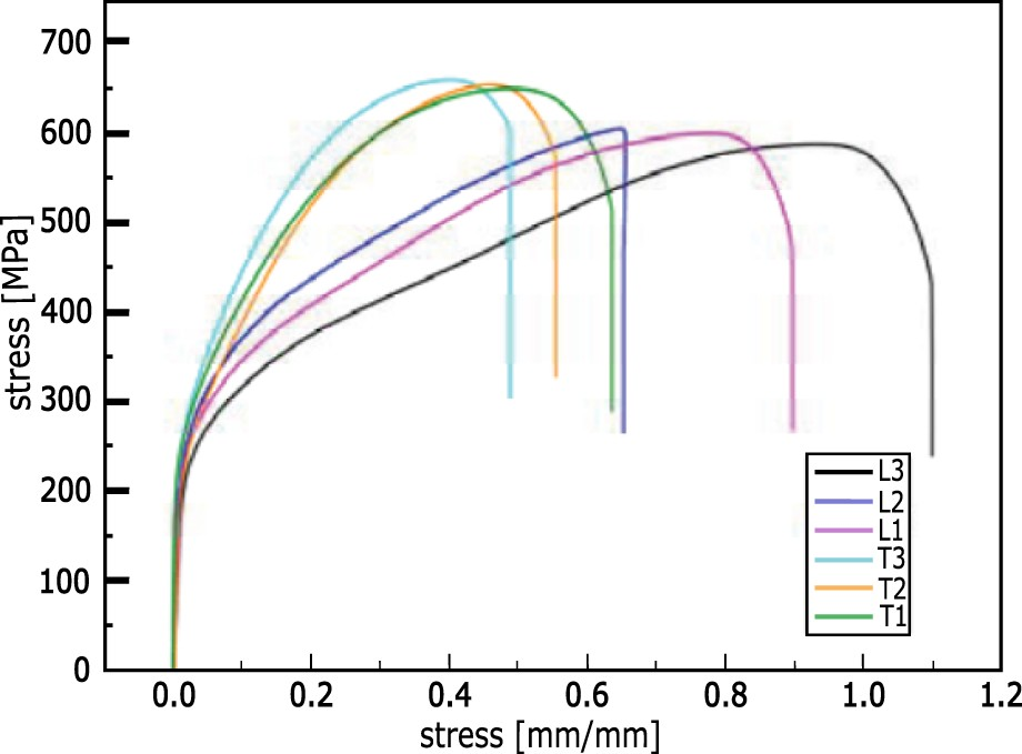
Titanium alloys are widely used in the aerospace industry due to their high strength-to-weight ratio [231]. The allotropic nature of titanium alloys, in addition to high-temperature thermal cycles associated with AM techniques, allows for various microstructures, and consequently, mechanical properties [232]. Moreover, titanium components with complex geometries cannot be easily fabricated using conventional manufacturing techniques due to titanium alloys' poor machinability. The low thermal conductivity of Ti results in poor thermal dissipation during machining, leading to poor surface quality, accuracy and reduces machining tool life [233]. These factors make titanium alloys an attractive candidate for AM. Ti–6Al–4V (Ti64) alloy contains an allotropic microstructure of hcp α- and bcc β-phases, and is the most widely AM-fabricated alloy among all metallic alloys [61, 65, 94, 134–136, 155]. AM-fabricated Ti–6Al–4V alloys exhibit higher strength but lower ductility than conventional manufacturing techniques such as casting and forging [66, 151]. This can be explained by the formation of α'-martensite due to the high cooling rates associated with the selected AM techniques. The ductility of AM-fabricated Ti–6Al–4V components can be enhanced by applying heat treatments at the cost of reducing the overall strength of the material [59, 112]. Zhai et al. used a high-power laser to fabricate Ti–6Al–4V components, resulting in an as-built UTS and elongation of 1042 MPa and 7%, respectively [59]. Similar mechanical properties were reported for the Ti–6Al–4V alloy fabricated by GMAW [112] and pulsed plasma arc AM [151]. These findings can be explained by the similarity in their microstructures, where fine acicular α'-martensite with a small amount of 

Columnar grains and strong crystallographic texture of 
Aluminium alloys
Aluminium alloys are the most extensively used non-ferrous metallic alloys in engineering components due to their high strength, low density, good ductility and high corrosion resistance. Additive manufacturing of aluminium alloys is more challenging than steels and titanium alloys due to their high thermal conductivity. Therefore, the power of the different heat sources needs to be increased during AM to prevent quick heat dissipation [115, 242]. This is especially prevalent when the heat source is a laser beam because aluminium alloys have a high reflectivity [73]. The optics train can be damaged from the reflected laser, which can be counteracted by introducing a minor z-axis tilt to the laser head [242]. The increased power of heat sources can lead to the evaporation of some alloying elements such as zinc and magnesium during manufacturing, resulting in porosity due to gas entrapment [243, 244]. This limits the range of aluminium alloys that can be fabricated by AM. Aluminium also forms a strong passive oxide layer on the feedstock material, reducing the wettability of the melt during fabrication [245]. The presence of a large solidification range is another factor limiting AM of aluminium alloys. The segregation of alloying elements during solidification decreases the melting temperature of the grain boundaries, creating a liquid film. The thermal stresses induced by the high thermal expansion of Al can cause intergranular rupture of the grain boundaries, resulting in hot cracking [116, 138, 246]. The addition of silicon has been shown to reduce the susceptibility of hot cracking by reducing the solidification range, enhancing fluidity, and decreasing the thermal expansion coefficient [244, 247]. Moreover, it forms a fine low melting eutectic structure that can backfill cracks and increase the grain boundary area, preventing crack growth [244]. Among aluminium alloys, AlSi10Mg is the most extensively AM-fabricated alloy [68, 71, 72, 248, 249], although others like Al 5356 [250–253] and Al 4043 [254–257] have also been studied. The alloy is a hypoeutectic Al–Si alloy with a composition close to eutectic. The presence of a small amount of magnesium (

Nickel alloys
Nickel alloys are extensively applied in gas turbine engines, nuclear reactors, rocket engines, submarines and space vehicles owing to their high strength and oxidation resistance at elevated temperatures [120]. Various nickel alloys have been used in the selected AM techniques including Inconel 625 (In625) [76, 261, 262], NiCrBSi alloy [92], Inconel 718 (In718) [97, 263] and Ni–Fe–V [264, 265] alloy. AM-fabricated Inconel 718 typically yields a dendritic structure of FCC γ, with the segregation of Nb and Mo to the interdendritic regions, characterized by the formation of Laves phase (


Magnesium alloys
Magnesium alloys are the lightest engineering metal available with an approximate density of 
Copper alloys
Copper and copper alloys are widely used for manufacturing heat sinks, electrical wires, tooling inserts, busbars, cooling components and electric motors due to their high electrical and thermal conductivity. Additive manufacturing allows the fabrication of complex geometries made from copper, such as internal cooling channels, while reducing the required material and shortening the manufacturing cycle. However, poor dimensional accuracy and significant porosity were observed in the AM-fabricated copper parts [270]. These problems are attributed to the rapid heat dissipation during AM resulting from the high thermal conductivity of copper. Thus, limited research has been conducted using the selected AM techniques to fabricate Cu components [126, 127, 144]. Dong et al. [144] fabricated a Cu–9 at. % Al parts using GTAW-AM, where separate pure Cu and Al wires were fed into a melt pool. The rapid solidification associated with GTAW-AM resulted in a microstructure predominately consisting of 

Cobalt–Chrome alloys
Cobalt–chromium alloys exhibit excellent wear resistance, high-temperature hardness, corrosion resistance and biocompatibility. They are extensively used in cutting tools, gas turbines, combustion engines, surgical prosthesis and machine gun barrels. However, their high hardness and low thermal conductivity quickly increase their temperature during cutting, making these alloys very difficult to machine. Thus AM can be a good candidate for manufacturing Co-Cr parts. The AM-fabricated microstructure is mainly composed of Co-matrix dendrites and inter-dendritic eutectic, similar to the as-cast microstructure. However, both the dendritic branches and eutectic structure of the AM components are significantly finer than those of cast ones [85, 88, 145]. This can be explained by the significantly higher cooling rates of the selected AM techniques compared to casting. As a result of the finer solidification structure of the AM parts, the inter-dendritic eutectic carbides mostly have a lamellar morphology [85, 88, 145]. This contrasts the coarse blocky eutectic carbides typically observed in the cast microstructure [145]. This explains the higher hardness, yield stress, and UTS of the AM parts compared to their cast counterparts [145]. However, compared with wrought Co–Cr alloys, the AM-fabricated Co–Cr alloys exhibit a comparable volume fraction of carbides and hardness value [88]. Moreover, the wear resistance of AM parts under dry sand/rubber wheel test conditions was reported to be less than that of the wrought ones [88]. This is attributed to the lamellar carbides of the AM deposit creating a continuous network that is easily removed during the wear test [88]. Mechanical properties and corrosion resistance of as-deposited AM Co–Cr alloys can be enhanced by performing post-processing heat treatments. The best combination of hardness, wear resistance and corrosion resistance was reported to be achieved when the as-fabricated component is subjected to solutionizing heat treatment without being aged [86].
Tungsten alloys
Tungsten and its alloys are widely used in many high-temperature applications such as collimators, arc welding electrodes, rocket nozzles and heating elements in high-temperature furnaces owing to their high melting point, low thermal expansion coefficient, high tensile strength and good creep resistance. However, their low ductility at room temperature and high ductile-to-brittle transition temperature (DBTT) limit their ability to be fabricated. Powder metallurgy (PM) techniques are commonly used to fabricate W components. However, parts with complex geometries are challenging to manufacture by PM techniques due to the limitation in mould/die geometry. Moreover, porosity is a common defect in PM-fabricated parts due to the high melting point of tungsten alloys. Thus AM can be considered a promising candidate for the fabrication of fully dense W components with complex geometries. Marinelli et al. [146] fabricated defect-free parts from pure W wires by a GTAW-AM technique using a front wire feeding approach. Both the grain structure and the number of structural defects (such as gas-trapped pores, keyholes and lack of fusion) were reported to be highly dependent on the orientation of the wire feeding [146]. In another study, Zhong et al. [90] used an LDED technique to fabricate a collimation component from pure W and W–Ni powder. No cracks or pores were observed in the microstructure of the as-deposited parts [90]. Both tensile strength and elongation of LDED W–Ni alloys are enhanced by the addition of Fe and Co [89].
Defects
This section will focus on the defects found in Ti–6Al–4V deposits across the different deposition technologies due to the lack of correlation between defects and the material or deposition system. The defects found are typically anisotropic microstructure [60, 64, 94, 156], porosity [58, 163, 236], thermal residual stress [64, 113, 157], lack of fusion [57, 161] and cracking [114]. These defects were found in LDED [57, 58, 60, 64, 93, 94, 96, 236], GMAW [110, 113, 114], GTAW [94], PTA [150, 151], and EB [156–158, 160, 161, 163, 165] deposits. Eliminating these defects is a challenge that will need to be overcome before the full commercialization of AM, especially for large-scale parts. Some of the remedies being explored are HIPing [65, 82, 156, 161, 271–273], hot rolling [134, 136], shot peening [83, 274] and cold working [275].
Fabrication platforms
This section introduces various considered fabrication platforms for the AM techniques discussed in Section 2 that were commonly found in the literature. For the context of this paper, an AM fabrication platform was considered as any actuated mechanical platform capable of carrying, translating and potentially re-orienting a deposition system – such as a laser cladding head or a GMAW torch – with the desired accuracy. Alternatively, the system can be designed to translate and re-orient the substrate plate onto which components are printed or a combination of both re-orientation of the substrate plate and translation of the deposition system. The platform can be programmed to carry out deposition trajectories, including the complete integration of the deposition system, where parameters can be adjusted, and deposition can be activated and deactivated.
A summary and comparison of various fabrication platform types.
A summary and comparison of various fabrication platform types.
Multiple groups of researchers – Anzalone et al. [280], Nilsiam et al. [281] and Lu et al. [282] – introduced open-source fabrication platforms where the substrate plate is actuated by a parallel mechanism, which allows for 5 degrees of freedom (DOF) motion enabling multi-directional deposition. The substrate plate can be translated in all three directions (x, y and z planes) and rotated about the two horizontal coordinates. The rotational capabilities are, however, not utilized when fabricating sample components with the proposed systems. In each system, the deposition system (a GMAW torch) is rigidly mounted above the actuated substrate plate. The system proposed by Anzalone et al. is shown in Figure 7(b). Each of the systems is highly cost effective at the proposed scale and type of hardware used. However, these systems have a limited build volume and re-orientation angles, making them ill-suited for larger parts. Another limitation is the limit of payload scaleability as the build plate's actuation system carries the full weight of the build. Sample of materials used in the various pieces of work discussed in Section 3.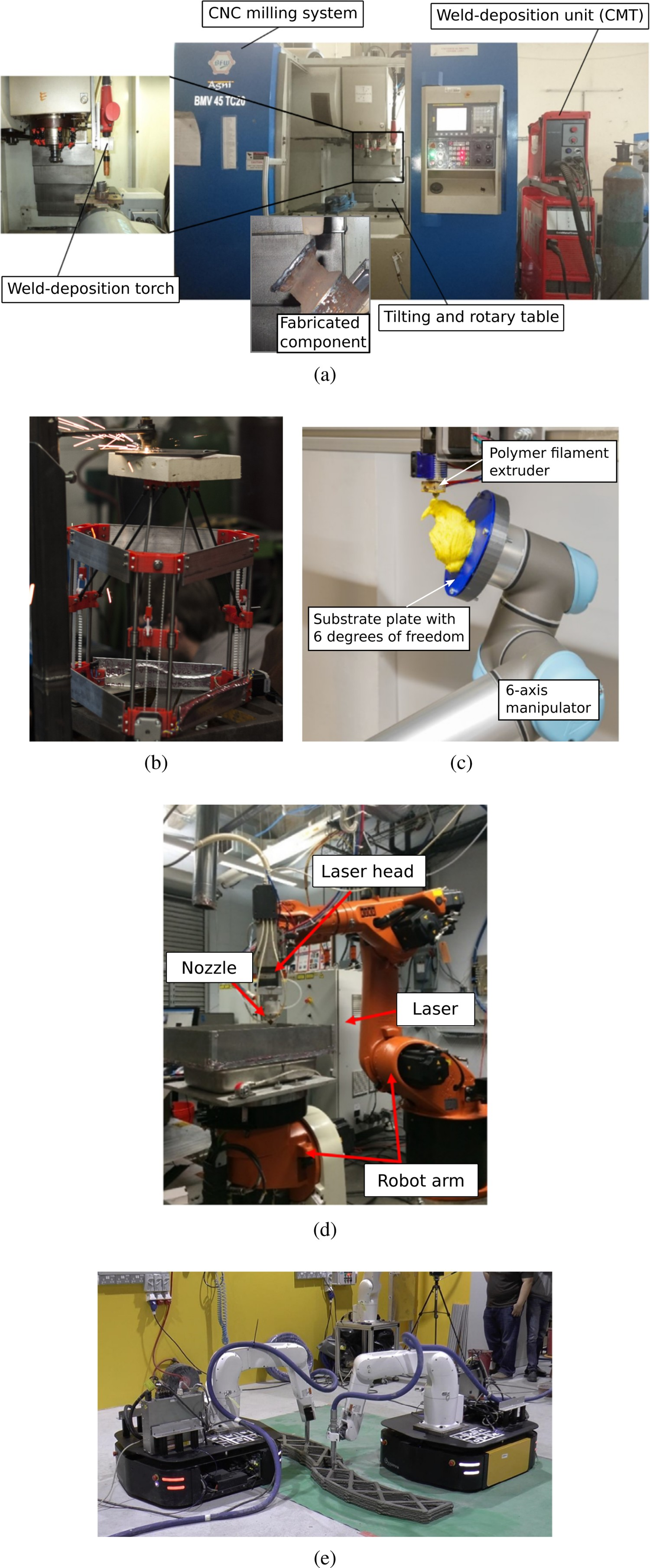
Another system type found in the literature that is capable of 5-axis AM is standard CNC milling systems retrofitted with a deposition system such as a GMAW or an LDED cladding head, introduced in Section 2.1 and Section 2.3 respectively. CNC milling machines have existing process planning and computer-aided manufacturing (CAM) infrastructure that can be integrated with these deposition systems, making them a popular industrial choice. This established pipeline of technology will be important in streamlining commercial 5-axis AM systems, especially for components of a limited size. Panchagnula et al. mounted a GMAW torch on the side of their CNC milling system's tool spindle, allowing the torch to be moved in three translational dimensions. Furthermore, the CNC milling system is equipped with a 2-axis positioner (see Figure 7a), enabling the substrate plate to be tilted and rotated. The combined total of 5 DOF allows for multi-directional deposition and, therefore, the fabrication of support-less components [22, 23]. A further 5-axis metal AM platform, where a CNC milling system was retrofitted with a laser cladding system was introduced by Tabernero et al. and Calleja et al. [276, 277], with similar capabilities as Panchagnula et al.
In addition to the above-listed 5-axis platforms, there are also commercialized 5-axis hybrid platforms for metal AM available such as the Mazak INTEGREX i-400 AM [278] and the DMG Mori LASERTEC 65 3D hybrid [279]. Each of these two platforms is equipped with an LDED deposition system and a tool spindle. A component is first fabricated, or a feature is added to an existing component through AM. The finished component or feature is then finalized by milling the surfaces to an accurate size. This combination of additive and subtractive manufacturing is gaining popularity in the industry due to the lack of geometrical constraints of AM coupled with the surface tolerances offered by subtractive manufacturing. This offers unique capabilities that are currently not achievable with either technology alone.
Another platform that can potentially be utilized for metal AM was first introduced by Wu et al. and Dai et al. and is shown in Figure 7(c). The platform consists of a 6-axis serial manipulator and a rigidly mounted deposition system above the manipulator. The substrate plate is mounted on the tool flange of the manipulator and can be moved in 6 DOF, allowing for multi-directional deposition [283, 284]. While both Wu and Dai et al. utilized polymer extruders as a deposition system, simple modifications could render it to be compatible with the metal deposition systems introduced in Section 2. One inherent limitation of this proposition is that the size of the component is constrained to the maximum payload of the manipulator, possibly limiting the scalability to large metallic parts. [16, 18, 34–37]
A better-suited metal AM fabrication platform uses a large-scale serial manipulator to carry the deposition system (6 DOF), while the components are fabricated on a two-axis positioner (2 DOF) such that the overall systems offers 8 DOF. These systems have various advantages over the reviewed parallel, 5-axis gantry-based, and 6-axis manipulator-based platforms. An advantage compared to 5-axis systems is that the deposition head's orientation can be changed in all three rotational directions when a 6-axis manipulator carries the deposition system. This capability to change the orientation also facilitates tangential continuity, allowing for smoother surface finishes and optimizing the feeding angle of material into the melt pool while maintaining alignment with the gravity vector for multi-directional deposition. During GMAW-based deposition, for example, specific drag or pull angles can help achieve the desired bead geometry. Another significant advantage, which has been appreciated since the 1980s for welding complex, curved contours is the redundancy of the 8-axis manipulator and positioner combination. Redundancy in the context of a kinematic system is when more degrees of freedom are available than are required to complete the desired task. Thus redundancy implies kinematic advantages such as enhanced relative reachability and dexterity between fabricated components and deposition systems.
The coordinated motion between manipulator and positioner offers the following advantages: reduction of execution time, added flexibility in motion optimization and collision avoidance, maximization of the manipulator workspace, and the ability to track smooth corners using smooth paths [287]. Generally speaking, manipulator/positioner combinations have been used for welding applications for over 30 years. Therefore, using these platforms for DED deposition is a natural extension of robotics research, where prior research can be utilized seamlessly.
The first example of using an 8 DOF system for DED was proposed by Dwivedi et al., where radial components were fabricated using multi-directional deposition. The authors used a powder-based LDED system for metal deposition [18] mounted on the manipulator's tool flange. Ding et al. [16, 34, 35] (see Figure 7d) and Zheng et al. [36] proposed equivalent platforms also using powder-based LDED as deposition systems. Ding et al. explored the augmentation of a 6-axis manipulator with a 2-axis positioner, totalling 8 DOF for multi-directional deposition, as shown in Figure 7d. The author eliminated the need for support structures while fabricating a propeller, which consisted of a core volume (a shaft) and radially overhanging features (propeller blades). Such a component is difficult to manufacture using conventional subtractive manufacturing [16]. Platforms utilizing arc-welding-based deposition technologies have been less explored in combination with 8-axis motion platforms than LDED-based deposition. Such a platform was used by Ma et al. for experimental trials with aluminium [37]. Moreover, in a collaborative effort between the University of Alberta and InnoTech Alberta in Edmonton, Canada, a robotic large-scale WAAM platform – as shown in Figure 1 – has been put in use by the authors of this work and initial research on parameter identification towards the optimization of deposition parameters is currently being conducted [177]. An interesting extension for robotic large-scale metal AM is the use of multiple mobilized manipulators, each carrying a deposition system. Research on such a platform in the area of civil engineering for the fabrication of concrete components using AM has been conducted by Zhang et al. The researchers propose a platform consisting of two 6-axis manipulators, each mobilized by a holonomic mobile platform where a concrete deposition nozzle is mounted on each manipulator's tool flange (see Figure 7e). A holonomic mobile platform can translate in any direction (sideways or forward) without the need to change the orientation of the platform, which means that the manipulators can reach any location within the fabrication space at an optimum duration and trajectory. Zhang et al. identified that the most significant advantage of this platform is the ability to fabricate components larger than the reach of one manipulator. The mobility aspect of the platform extends the reach of each manipulator, significantly enhancing the scalability and duration of fabrication. The extent of the scalability can be enhanced by increasing the number of mobile manipulators to the system. Some of the associated research challenges are robot localization, multi-robot coordination (e.g. swarm intelligence) and collision-free motion planning, and robot placement accuracy and optimization [286]. While Zhang et al. proposed platform is not capable of multi-directional deposition, a multi-manipulator platform can also be augmented with a large-scale multi-axis positioning system in order to facilitate multi-directional deposition.
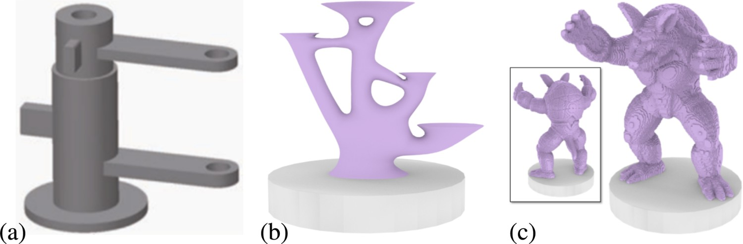
Process planning refers to converting a 3D model of a component to an optimal manufacturing strategy prior to fabrication. An integral part of this strategy for multi-directional large-scale AM is avoiding support structures as commonly required for 2.5 DOF AM. Depending on the geometric complexity of the overhanging features, the 3D model is decomposed into sub-volumes typically consisting of a core volume and multiple overhanging features. These are then sliced into cross-sectional layers, followed by the generation of an optimized deposition tool path for each layer. An example of such a process planning sequence is shown in Figure 8 [16]. This example shows the decomposition of a propeller where a clear separation between core volume (shaft) and the overhanging features (propeller blades) can be found. For many other components, however, this separation is less obvious or nonexistent (see Figure 9). An example of a process planning sequence on a 3D model of a propeller including volume decomposition, slicing and path planning of each sub-volume. (Image source: [16])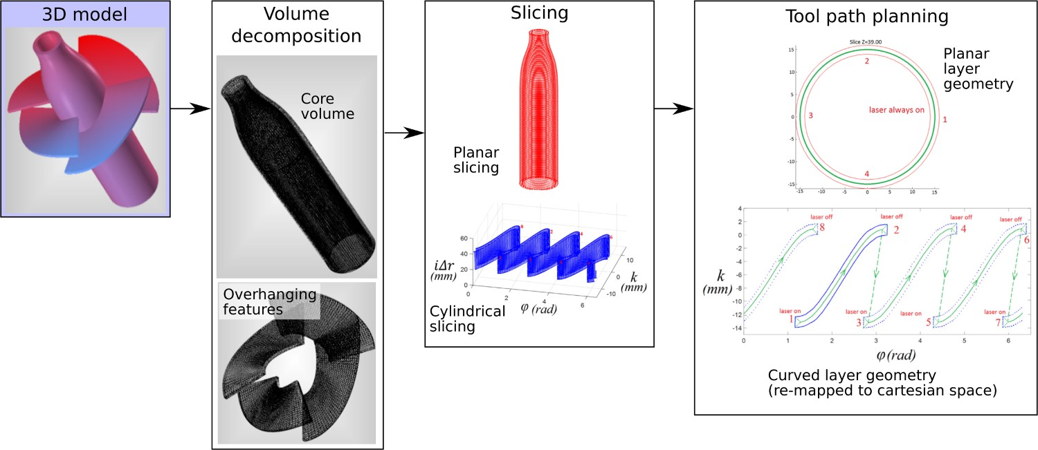
After slicing is complete, a deposition tool path is computed that fills the required areas of each layer with material. Using a numerical model, the bead geometry (bead width and height) required to fill the layer to a predetermined height is correlated to a set of deposition system parameters, including the material feed rate, deposition system speed and dwell times. The magnitudes of these parameter values depend on the material and deposition technology being used. This information is then provided to the fabrication platform, theoretically allowing for unsupervised deposition.
Materials used in various pieces of work discussed in Section 4.
Some of the first researchers to recognize the need for an advanced process planning framework capable of decomposition and multi-directional slicing of complex 3D models with overhangs were Sing and Dutta [17]. The objective of their proposed method was to improve the surface accuracy and reduce the support volume through multi-directional deposition. The decomposition sequence is as follows: choose a build direction; by default along the component's Z direction to avoid collision of the deposition head with the table, identify and decompose overhanging features (often referred to as ‘unbuildable structures’ in the literature) in build direction, determine the build direction for each sub-volume and sequence and slice each sub-volume along its computed build direction.
At the core of the approach is a recursive volume decomposition scheme meaning that overhanging features within sub-volumes are also identified. The performance of the proposed process planning framework was shown on two example 3D models, but no components were fabricated. Dwivedi et al. proposed a framework for automated process planning for LDED [18]. The process planning framework is based on first-order logic and a knowledge base consisting of rule and fact attributes represented by a semantic tree structure. The authors of the study successfully verified their framework on a radial component consisting of 5 helical blades. Ruan et al. proposed a method using the centroid axis of a component to compute the deposition direction to produce collision-free slicing directions for multi-directional deposition [291]. The basic tasks are defined as centroid axis computation and formation and collision-free multi-axis slicing based on the centroid axis.
The detection of change in build direction – and therefore slicing direction – is based on the degree of shift from the centroid axis. The slicing algorithm can produce layers of non-uniform thickness, thus requiring the deposition system to be capable of producing beads of varying geometry. The algorithm was verified on a 3D model of a hinge with overhangs on a multi-axis LDED fabrication platform. Ren et al. identified limitations with the previous centroid-axis-based decomposition algorithms for certain corner cases of axis-symmetric overhanging structures where no shift in the centroid axis occurs. Thus an algorithm combining the centroid-axis-based and boundary-based decomposition methods – where concave edges and loops mark the interface between core volume and overhanging feature (see Figure 10) – of the type as previously proposed by Singh and Dutta [17] was introduced [290]. Furthermore, the authors proposed a method for representing layers of non-uniform thickness by further decomposing the non-uniform layer into uniform sub-layers of a smaller cross-section than the parent layer. The algorithm was verified by fabricating a turbine wheel with a conical shaft and winged blades on an LDED platform.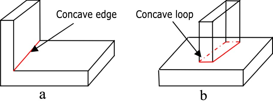
In order to further improve non-planar interfaces between a core volume and overhanging feature, Singh and Dutta further extended their previous work on multi-directional deposition [17], by introducing so-called offset slices, which are essentially non-planar layers [295]. The concept of offset slices is illustrated in Figure 11. if the base surface is non-planar, which is frequently the case for radial components with overhanging features, the build quality of the overhanging features can be significantly improved when each layer follows the same contour as the core volume and subsequently the previous layer. The concept of offset slices as introduced by Singh and Dutta [295]. (a) shows a contoured base surface and (b) is the corresponding offset slices. The offset slices follow the contour of the non-planar base surface where each offset slice is equidistant to the previous one.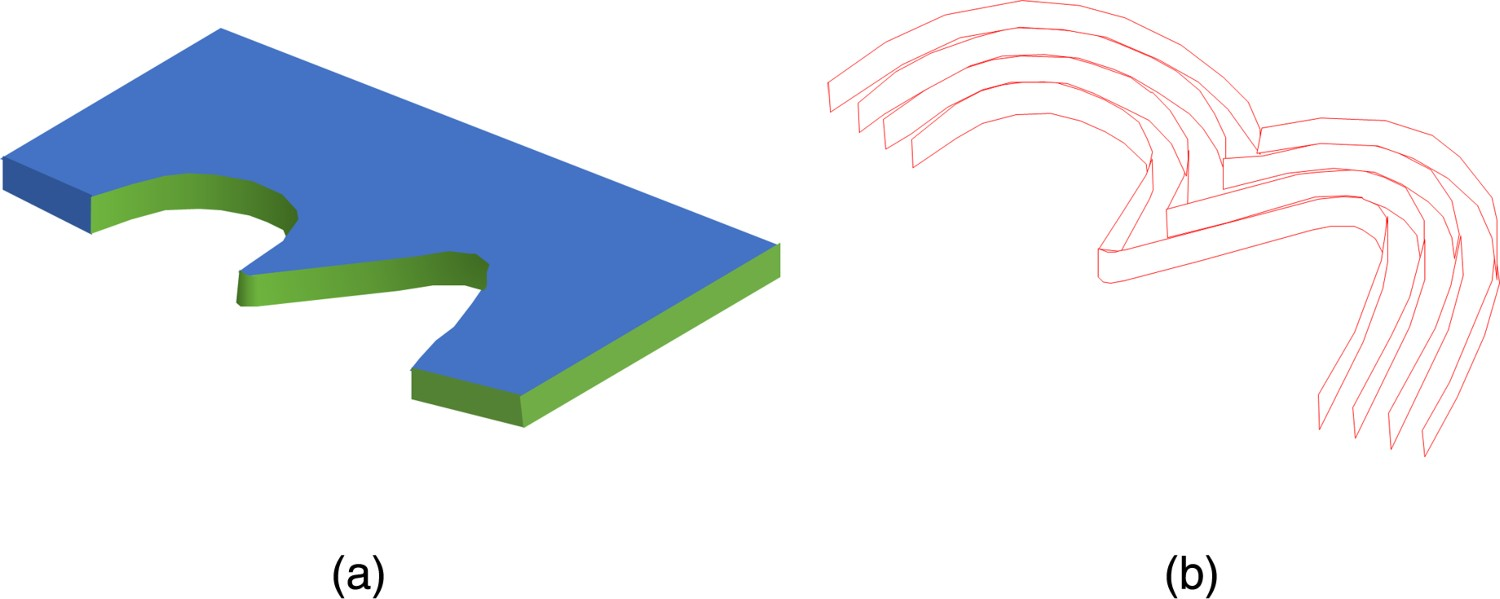
In order to simplify process planning and fabrication of special cases of components with overhanging features containing holes (see Figure 9a), Ding et al. proposed a framework that fills all holes and protrusions within the 3D model prior to decomposition [288]. The volume decomposition itself is boundary based, whereas, with previous algorithms, concave loops and edges are detected. After decomposition, each sub-volume is sliced into planar layers according to the identified build direction. The framework was not verified experimentally. Furthermore, due to the hole-filling operation prior to decomposition, additional post-processing is required to drill the holes.
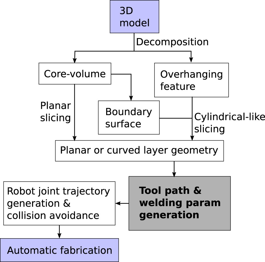
Ding et al. introduced a process planning framework for radial components such as propellers or impellers [16], shown in Figure 12. The decomposition algorithm is based on silhouette edges, as first introduced by Singh and Dutta [17], and Dwivedi et al. [292]. The algorithm is similar to previously proposed boundary-based algorithms as it looks for concave edges and loops on the core volume. Slicing is divided into two steps (see Figure 8): planar slicing of the core volume, typically a cylindrical volume for radial components and mapping of the overhanging feature's curved geometry from a cylindrical to a cartesian coordinate system to allow for a planar representation of each curved layer, similar to the principles proposed by Singh and Dutta [295]. Flowchart of an example process plan similar to the one devised by Ding et al. for propeller fabrication [16].
The process planning framework was verified on a 8-DOF robot LDED platform (see Figure 7d) by fabricating the propeller model shown in Figure 8.
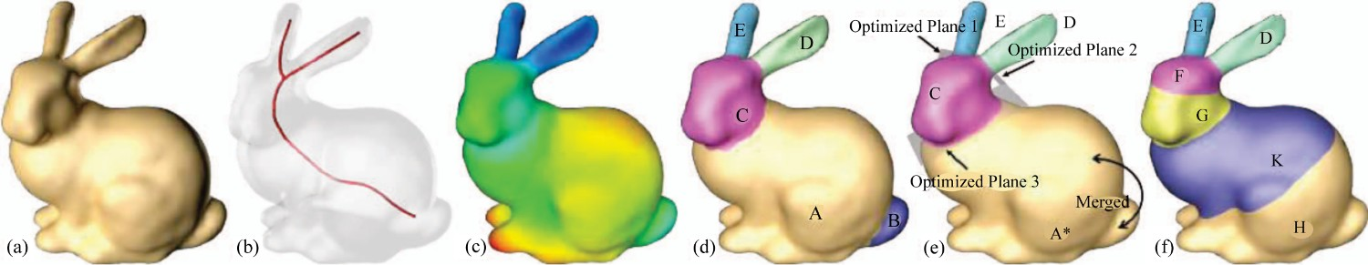
It should be noted that all of the frameworks for process planning reviewed up to this point can only process components where the overhanging features are sharp concave edges or concave loops (see Figure 10), meaning that they are distinguishable from the core volume. The works reviewed in the following, however, propose process planning algorithms and frameworks designed for volumes with non-sharp edges that are more difficult to decompose (see Figure 9b and Figure 9c). Wu et al. introduced an advanced volume decomposition algorithm capable of processing volumes that are not composed of a distinguishable core and overhanging volumes (see Figure 13a) [283]. The decomposition algorithm consists of 3 major steps as illustrated in Figure 13:
Coarse decomposition: A skeleton is generated based on a mean – curvature flow algorithm (see Figure 13b) followed by the computation of a distance metric–the shape diameter function (SDF) – between volume boundary and skeleton (see Figure 13c) and partitioning the mesh using the distance metric based on [296]. The partitioning algorithm identifies significant differences in the SDF and creates a boundary plane where the change occurs. When considering the bunny model, a significant change in SDF can be found at the bunny's neck, ears, and tail.
Sequence planning: A graph is constructed that defines the preliminary build sequence – nodes are the sub-volumes – and the print orientation for each sub-volume is determined (see Figure 13d). The preliminary build sequence is A
Constrained fine tuning: The decomposition is refined and re-configured to satisfy manufacturing constraints (see Figure 13e and Figure 13f). For example, the bunny tail as labelled B in Figure 13d cannot be manufactured with the platform shown in Figure 7(c) due to inaccessibility. It, therefore, needs to be merged with A. In addition, A* needs to be separated into H and K since the belly of the rabbit is an overhanging feature. The volume decomposition algorithm proposed by Wu et al. [283] with (a) the input 3D model, (b) the extracted skeleton, (c) the shape diameter metric (distance of every point to skeleton), (d) the result of initial decomposition and sequence planning, (e) after merging (B into A), and (f) the final result after fine decomposition to ensure manufacturability. (Image source: [283])


The decomposition algorithm was verified experimentally on a robotic AM platform equivalent to the one shown in Figure 7(c).
One limitation of Wu et al. work is that it relies on planar layers, which imposes constraints on the manufacturability of more complex components (see Figure 9c). Dai et al. proposed a novel method utilizing curved layer decomposition relying on dimensionality reduction [284]. The algorithm is separated into the following steps as illustrated in Figure 14: The volume decomposition algorithm proposed by Dai et al. [284] with (a) the input 3D model, (b) after voxel discretization and voxel sequencing where the color scheme represents the fabrication sequence by layer, (c) generated curved layers based on (b), and (d) a detailed view on a computed tool path. (Image source: [284])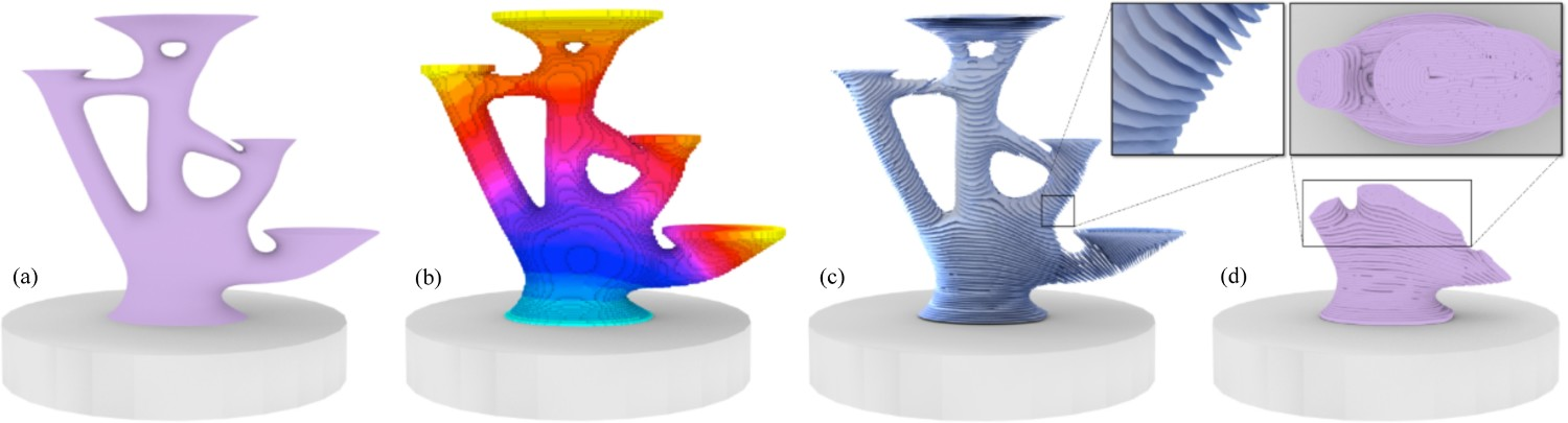
Discretization of the input model into a voxel grid – a discretization into small cubes – where the voxel dimensions are determined by the deposition system's resolution (Figure 14b). This is done to reduce the computational load on the following steps since the volume decomposition of the input model is posed as a global search problem.
Sequencing of the voxels to obtain a sequence of voxel accumulation representing the flow of fabrication. By iterating over all voxels, satisfying manufacturing constraints can be significantly simplified. The colour scheme shown in Figure 14b represents the voxel sequencing by layer.
Computation of each curved layer while avoiding voxel aliasing (see Figure 14c).
Computation of a tool path for each layer using the method introduced by Zhao et al. and based on Fermat spirals [294] (see Figure 14d).
This algorithm was also verified experimentally on a robotic AM platform equivalent to the one shown in Figure 7(c). The limitations of the algorithm identified by the authors include the reliability of thin-feature deposition, fabrication errors due to the used hardware, and voids in the filling patterns of the tool path planning algorithm.
Despite the limitations of the frameworks and algorithms proposed by Wu et al. and Dai et al., their works contain important contributions to process planning of complex models with significant adoption potential to metal AM.
Once the component has been decomposed and sliced into cross-sectional layers, the optimal path to accurately deposit the material within the boundaries of the cross-section is computed. This process is known as tool path planning. An optimized deposition path planning strategy results in dense parts with minimized residual stress, free of any porosity, better control of anisotropic microstructures, mitigation and minimization of heat accumulation, geometrical accuracy and a smooth surface finish [24]. In order to develop an optimal deposition path planning strategy, features that are unique to various kinematic systems and deposition technologies (consistency of deposition, motion delay, dynamics, lag) need to be considered. Notably, the varying delays and inaccuracies in deposition system motion (especially for larger systems with increased mass) and material deposition (material feeding, melting) that are difficult to predict can cause unwanted variations on the rate of deposition and therefore complicate path planning significantly [47]. Inter-layer dwell time, start-stop minimization, smooth directional changes, as well as minimization of weld path cross-overs, are some of the commonly adopted strategies to mitigate these complications [47, 49, 293]. Towards the development of an optimized path planning strategy, Ding et al. identified various requirements for WAAM such as geometrical accuracy, minimization of start-stop points, minimization of rapid directional changes caused by sharp corners in every tool-path pass, and simplicity allowing for fast implementation [47].
Ding et al. reviewed various path planning methods with respect to their suitability for WAAM, using the above-mentioned evaluation criteria. Among the reviewed path planning algorithms are: Raster [297], Zigzag [298, 305], Contour [306–308], Spiral [301, 309], Fractal Space Filling Curve [302, 310], Continuous [303, 304, 310] and Hybrid (Combination of contour and zig-zag) [19, 299]. However, Raster (see 15 a), Zig-zag (see 15 b), Contour (see 15 c), Fractal (see 15e) and Spiral (see 15f) should be entirely avoided for metal AM due to the many issues listed by Ding et al. [47]. Raster and Zig-zag suffer from poor outline accuracy due to discretization errors on non-parallel edges. Contour generates many disconnected closed curves, therefore violating the requirement to minimize start-stop points. Fractal Space Filling Curve involves many path direction change motions, violating the requirement to minimize rapid directional changes. Finally, the Spiral method is only suitable for unique geometrical models that are convex [47]. Hence, these methods will not be reviewed in detail in this section. Different path planning methods: (a) Raster, (b) Zig-zag, (c) Contour, (d) Zig-zag and contour, (e) Fractal curves, (f) Spiral, (g) Continuous, (h) Hybrid, (i) CPG, (j) MAT, (k) Adaptive MAT, and (l) Straight skeleton and weaving deposition strategy.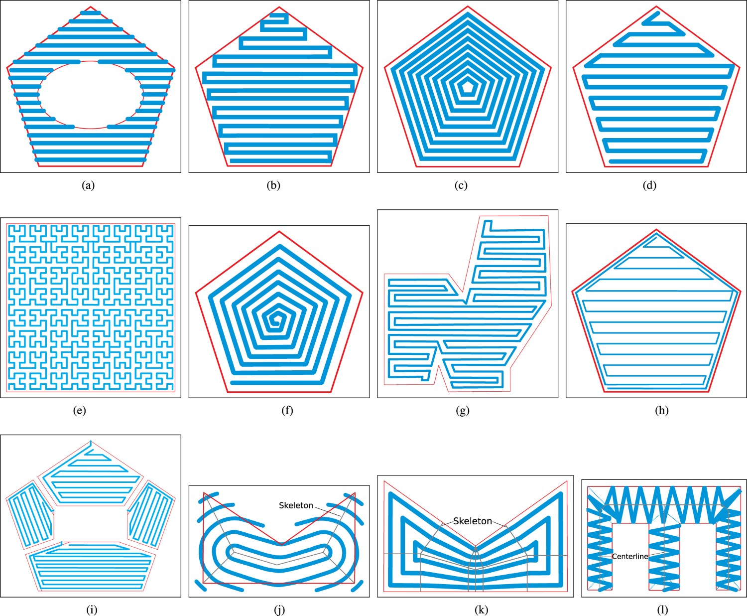
The Hybrid method (see Figure 15h) is a combination of the Contour and Zig-zag methods in that first, the contour of the layer boundary is traversed followed by filling the interior of the layer with the Zig-zag and Contour method (see 15 d). As this method combines the advantages of the Zig-zag and Contour methods, it is particularly promising for WAAM as it meets both the geometrical accuracy and surface quality. According to Ding et al., the Hybrid method is still insufficient due to the increased amount of tool-path passes and tool-path elements [47].
Ding et al. therefore proposed a novel tool path planning method intended to address the limitations of the previously proposed methods [47] and to conform with the aforementioned requirements: geometrical accuracy, minimization of start-stop points, minimization of rapid directional changes, and simplicity of implementation. The method is henceforth referred to as Convex Polygon Generation (CPG, see Figure 15 i). In order to generate a set of simpler convex or monotone sub-polygons, and to simplify the implementation of path generation for each sub-polygon, a polygon decomposition algorithm first decomposes each 2D slice via a divide-and-conquer strategy. Then the Hybrid path planning method is used for tool path generation due to the aforementioned advantages of this planning method. After tool paths are generated for each sub-polygon, the sub-paths from each sub-polygon are connected into a closed curve that spans the entire layer, thus minimizing start–stop points [47]. This algorithm extends the Hybrid path planning method to polygons with an arbitrary complexity through convex polygon decomposition. As this method, however, also utilizes the Zig-zag method for space-filling, voids can still occur [47, 49].
To address the issue of voids while retaining geometrical accuracy, Ding et al. proposed a method based on Medial Axis Transformation (MAT), or also referred to as skeletonization, as depicted in Figure 15(j) [48]. MAT was first proposed by Blum to describe shapes [311] by generating tool paths in a contour-like fashion from the centre outwards along a skeleton to the boundary of the geometry. First, the skeleton or the branch lines are generated, followed by the generation of loops representing the tool paths at a given step-over distance, which is the distance between passes representing the resolution of the deposition system [48]. With this method, the occurrence of voids is minimized. However, there are some disadvantages, such as start- and stop points and discontinuities at the geometry boundaries and deposition beyond the geometry boundaries [49]. While these deficits can be mitigated by post-process milling, they essentially limit the MAT path planning method to hybrid manufacturing.
Further iterating on their previous work with the objective of addressing the deficits raised with MAT, Ding et al. proposed adaptive MAT [49]. The difference being that the tool-path elements are designed so that the contour of the geometry boundary is followed and discontinuous path segments are minimized (see Figure 15 k). Benefits of adaptive MAT include the capability of generating continuous tool-path elements and following the geometry contour, void-free layers, good geometrical accuracy, and thus minimal post-milling, and suitability for thin-wall structures. For adaptive MAT to produce void-free deposition, the bead geometry must be able to be varied in-situ. To facilitate bead geometry adjustment, Ding et al. developed a Neural-network-based model that takes the desired bead geometry as an input and outputs welding parameters that significantly influence the bead geometry. Moreover, the adaptive MAT algorithm is experimentally validated using the proposed deposition model [300].
In summary, some of the variants of Contour-based algorithms such as Hybrid, CPG and adaptive MAT are preferred over raster or pure Zig-zag algorithms since they are more suitable for thin wall structures and allow for improved geometric accuracy, void-free deposition, and minimization of start-stop discontinuities in tool paths. Among the more suitable tool path planning methods, adaptive MAT is preferable from the aspects of void-freeness and accuracy if in-situ bead geometry adjustments are possible or feasible for a given deposition system.
A further tool path planning method specifically designed for the particular case of thin-walled structures with varying thickness was proposed by Ma et al. [37]. The adjustment of the wall width is achieved through a weaving trajectory where the weaving amplitude is the same as the width of the thin wall. After computing the skeleton of the polygon, the centreline is then obtained (see Figure 15 l), which constitutes an approximation of the polygon's median axis. During deposition, the torch weaves about the centreline in a triangular way, as illustrated in Figure 15l. The authors of the study successfully fabricated multiple thin-walled components with gradually varying wall thickness through this weaving technique.
As can be seen from this section, process planning is an integral part of robotic metal AM and involves many algorithms and software components. The cascade of complex software needs to interface and exchange information efficiently to provide robust performance while simultaneously providing flexibility, modularity, and reusability to integrate new algorithms and software in a research environment. For robotic research platforms, the used software frameworks facilitating novel research need to be as open as possible. This enables maximum flexibility and customization for each software component across research groups within the toolchain and facilitates the integration of custom hardware (HW).
A popular open-source software framework and middleware providing such a software ecosystem for advanced robotics research is the Robot Operating System (ROS). ROS is leveraged for wide varieties of robotics research and provides structured messaging between software components, robot-specific tools and libraries, various visualization and convenience tools, HW abstraction, low-level device control, and tools and libraries for obtaining, building, writing, and executing code [312]. ROS, therefore, simplifies and facilitates robotics research and software development significantly. The ROS software package MoveIt!, for example, provides interfaces to sophisticated path planners for free-space motion and inverse kinematics solvers for industrial robot arms such as the one shown in Figure 1.
In recent years, multiple open-source software frameworks have been developed within the ROS ecosystem for the planning of complex cartesian trajectories with an emphasis on industrial robotics applications such as welding, routing, milling, deburring, and grinding. In 2015, Edwards et al. introduced a path planning software package called Descartes for semi-constrained cartesian trajectory planning [313]. The software takes a 6-DOF cartesian trajectory that can be under-defined and is generated for any industrial application. Under-defined means, for example, that there is no rotational constraint on the rotation about the vertical axis of a welding torch. This enlarges the inverse kinematics solution space such that there are more options for the joint trajectory planner to avoid collisions.
Armstrong introduced a further cartesian path planning stack (collection of packages) called Tesseract for complex industrial motion planning applications with flexibility and modularity in mind [314]. The stack offers features such as fully and semi-constraint cartesian motion planning and free space planning. A significant advantage of this package, particularly towards multi-directional deposition, is its capability to plan collision-free trajectories between two moving coordinate frames, therefore enabling planning of coordinated motion between a positioner and manipulator (see Figure 1).
While there is currently an open-source robotic AM software framework available (ROS AM) [315], providing limited 2.5-DOF slicing capabilities, tool path visualization, and AM-specific message definitions, significant limitations exist. Besides being limited to 2.5-DOF AM, there is no generalized, hardware-agnostic and computer-integrated interfacing with the hardware available since post-processors generate instructions written in a hardware-specific language that only allows for open-loop execution.
In-situ process monitoring, modelling and control
Commercializing large-scale AM systems will require a high degree of self-regulation and automation to eliminate the need for highly skilled personnel to operate and monitor the fabrication process. To maintain compliance to mechanical, metallurgical and geometrical specifications and design constraints, the bead geometry, layer geometry, weld pool temperature and cooling rate need to be controlled in real-time as the component is fabricated (in situ). A significant proportion of this is dictated through the optimization of the operating parameters based on the material system and the planned tool path. Changes to the system's heat input (welding current/voltage, laser power), material feed rate and deposition system travel speed can drastically alter the geometry of the bead of deposited material and ultimately the success of the manufacturing process. During the fabrication stage, sensors and optical systems can be used to monitor measurable aspects of the deposition. This information can then be used as feedback to control the operating parameters of the fabrication platform. This allows for better adherence to the desired tool path generated during process planning while detecting and mitigating any defects created by non-ideal tool path planning (voids, gaps).
A basic control scheme for in-situ control of metal AM processes is shown in Figure 16. Process monitoring and control of the AM fabrication platform can be divided into three categories: condition monitoring, build monitoring and environmental condition monitoring. The first category impacts the outcome of deposition and includes the power source (arc voltage and current, laser power, etc.) for heat input assessment, material feed rate and deposition head motion speed for deposition rate estimation and evaluation, and shielding gas flow for oxidation level determination. This is achieved using electrical sensors to monitor instantaneous voltage and current, mechanical sensors for positional and feed rate estimation, and flow sensors for various fluid flow rates. The second category includes the observation of the following conditions: geometric shape, build temperature, cooling rate, heat accumulation, melt pool state and inferred metallurgical considerations. The typical sensing modalities include: Optical sensors for evaluation of bead and layer geometry (profilometer, 3D scanner, charged-coupled device (CCD) and complementary metal-oxide-semiconductor (CMOS) cameras), thermal sensors (infrared (IR) camera, pyrometers and thermocouples) for molten pool condition and temperature monitoring, and overall build temperature monitoring. A basic monitoring and control schematic for robotic metal AM processes.
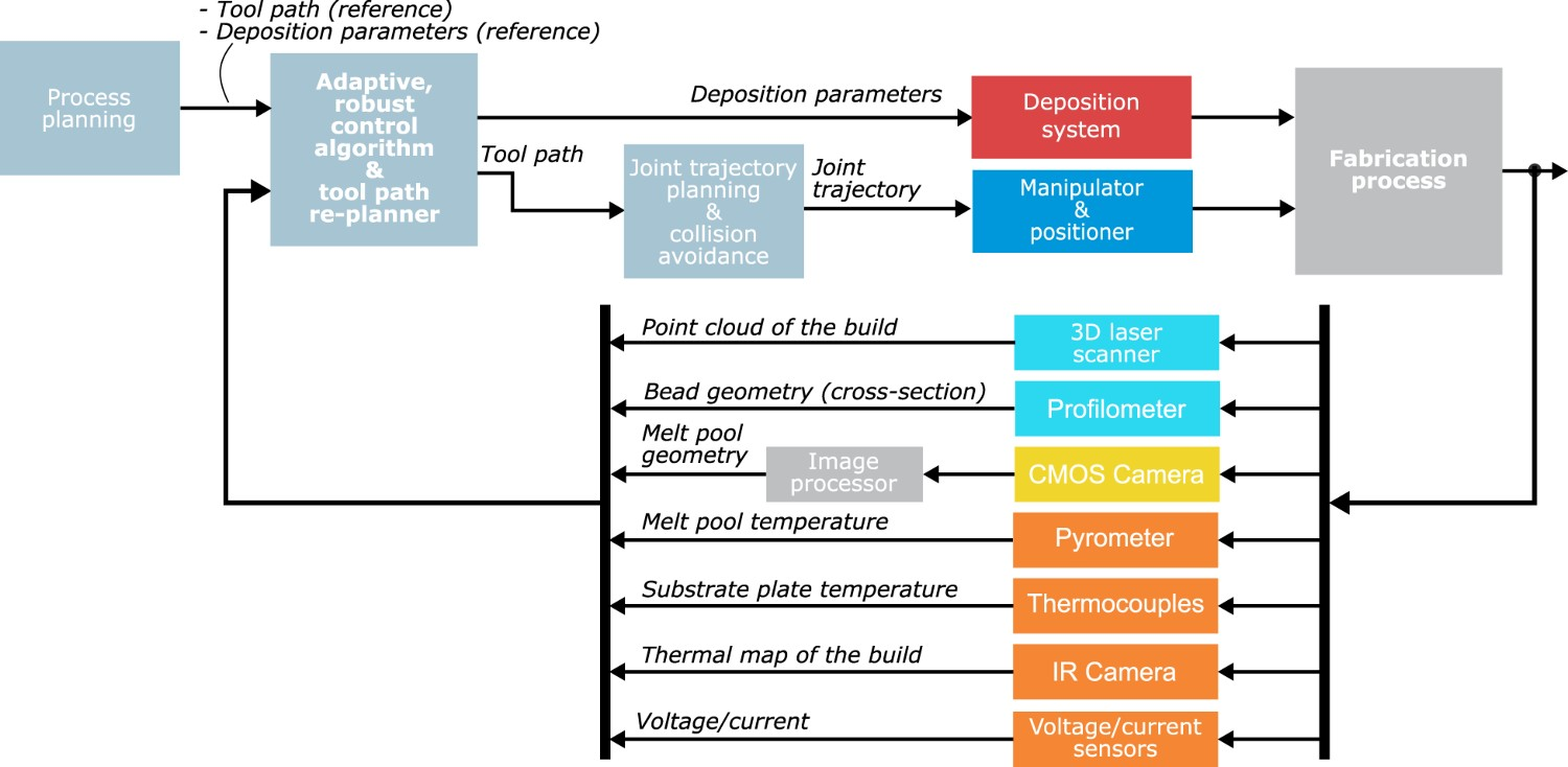
Calibration and validation experiments are imperative to ensuring the functionality of the various in-situ monitoring methods. This is especially important for thermal sensors like IR cameras, where electrical sensors measure the thermal energy emitted from an object and convert it to a temperature. The emissivity, which is the efficiency at which natural objects radiate heat, must be determined to ensure that the temperature measured by the IR sensor is correct [316]. This can be done in situ using an emissivity probe or post mortem by measuring the temperature with a different calibrated thermal sensor, and adjusting the emissivity value until the temperatures match. With emissivity being a function of both temperature and surface roughness, unless extreme care is taken to validate the temperatures measured by infrared sensors, these results should be taken as qualitative [316].
Structural defects (absence of fusion, porosity and cracks) can be evaluated by acoustic signal propagation measurement inside the part or even radio-graphic reflections. The third category can entail arc image, 
Some literature review works on in-situ sensing and control have previously been published. Tapia and Elwany reviewed multiple sensors primarily utilized to conduct studies on monitoring of metal-based AM [317]. Purtonen et al. also presented an overview of monitoring and control techniques using laser-based metal AM [318]. Everton et al. reviewed AM in-situ monitoring methods, research in the field of in-situ analysis for AM processes, and state-of-the-art for major process control technologies of metal AM [319]. They remarked that monitoring has been done mostly for process understanding rather than identifying defects and part discontinuities. This highlights the lack of holistic understanding of the implications that various processing conditions have on the metallurgical quality of the deposit, on both the macro and micro scales. Although process understanding is a step in the right direction, the collaboration between the different engineering disciplines involved in AM can extend the capabilities of process monitoring and control modalities to correlate the quantifiable manufacturing conditions to optimize metallurgical and mechanical properties.
Materials used in the various pieces of work discussed in Section 5.
When joining two components using welding, the need for in-situ inspection of the welding bead geometry arises from the need to detect weld defects, as these typically lead to topological variations on the surface of the bead. This need to monitor and control the shape of the weld bead also extends to metal AM as an important means to ensure the quality of an additively manufactured component during fabrication. Observing and controlling the bead's adherence to the desired geometry (width, height, and curvature) determined during process planning is essential to avoiding voids, porosity and geometrical inaccuracy of the final build. Bead height control is also important to maintain a constant distance between the deposition head nozzle and the melt pool, known as the stand-off distance. For welding techniques, the stand-off distance dictates the voltage of the system.
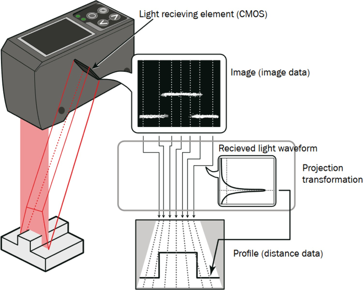
One of the most common sensing methods used for detecting weld defects is based on laser line scanners (also referred to as profilometers) that are mounted on the deposition head and observe the cross-section of the bead's geometry (height, width, curvature) almost directly after deposition [327, 328]. Profilometers are now standard equipment in the manufacturing industry for various inspection tasks due to their high accuracy ( The operating principle of a laser line scanner (profilometer). (Image source: [350])

Early work on a method for in-situ measurement of bead geometry during wire-and-arc welding using a profilometer with multiple deposited layers was introduced by Doumanidis and Kwak [331]. The bead profile obtained from the profilometer is used to validate a real-time analytical deposition model and provide feedback to a closed-loop control system for bead surface geometry control. Li et al. designed a scanning system and algorithms for feature extraction and dimension measurements to measure the dimensional properties of the weld, including groove width, bead width, filling depth and reinforcement height, in root- pass and cap welding [327]. Flaws such as plate displacement, weld bead misalignment and undercut were detected via the proposed feature extraction method. Huang and Kovacevic also designed a scanning system for monitoring the weld joint [328]. Furthermore, a computer-vision-based seam tracking controller and a feature tracking algorithm were developed for tracking weld bead features such as the width and height of the bead.
Many methods for bead geometry control utilize the above-introduced monitoring modality. However, there are also camera-based monitoring methods used for control feedback. It should be noted that the optical vision system required some neural and narrow-band filtering to remove the intensity of the arc and allow for the observation of the weld pool [329]. In the following paragraphs, the literature on bead geometry modeling and control methods and algorithms is reviewed.
Iravani-Tabrizipour and Toyserkani proposed a vision-based system for in-situ measurement of clad height during LDED [332]. A trinocular arrangement of three cameras pointed at the melt pool at an angle of 

Xiong and Zhang developed a passive-vision-based method for measuring the bead geometry in situ during multi-layer, single-track GMAW-deposition of a thin wall [329]. A schematic of the experimental setup is shown in Figure 18(a). The vision system captures a side and top view of the weld pool and the solidification area after the weld pool. Basic image processing techniques such as edge detection combined with Hough transform are used to find the bead width and height. Images with overlaid bead geometry detection are shown in Figure 18(b) and Figure 18(c). Validation experiments indicate a relative error of 5.7% between the ground truth and the vision-based measurement, which would be an error of 0.171 mm for a bead height of 3 mm. The passive-vision-based bead geometry measurement method proposed in [329] is then used by Xiong et al. for in-situ feedback control of the bead width [333]. The control algorithm – a segmented neuron self-learning Proportional Summational Differential (PSD) controller – takes the measured bead width as feedback and adjusts the torch travel speed to keep the bead width constant across layers. Disturbances in the bead width are due to variations in the shape of the previous bead and the slumping of subsequent layers caused by accumulating heat. The experimental results show that better consistency in the bead width can be achieved across layers.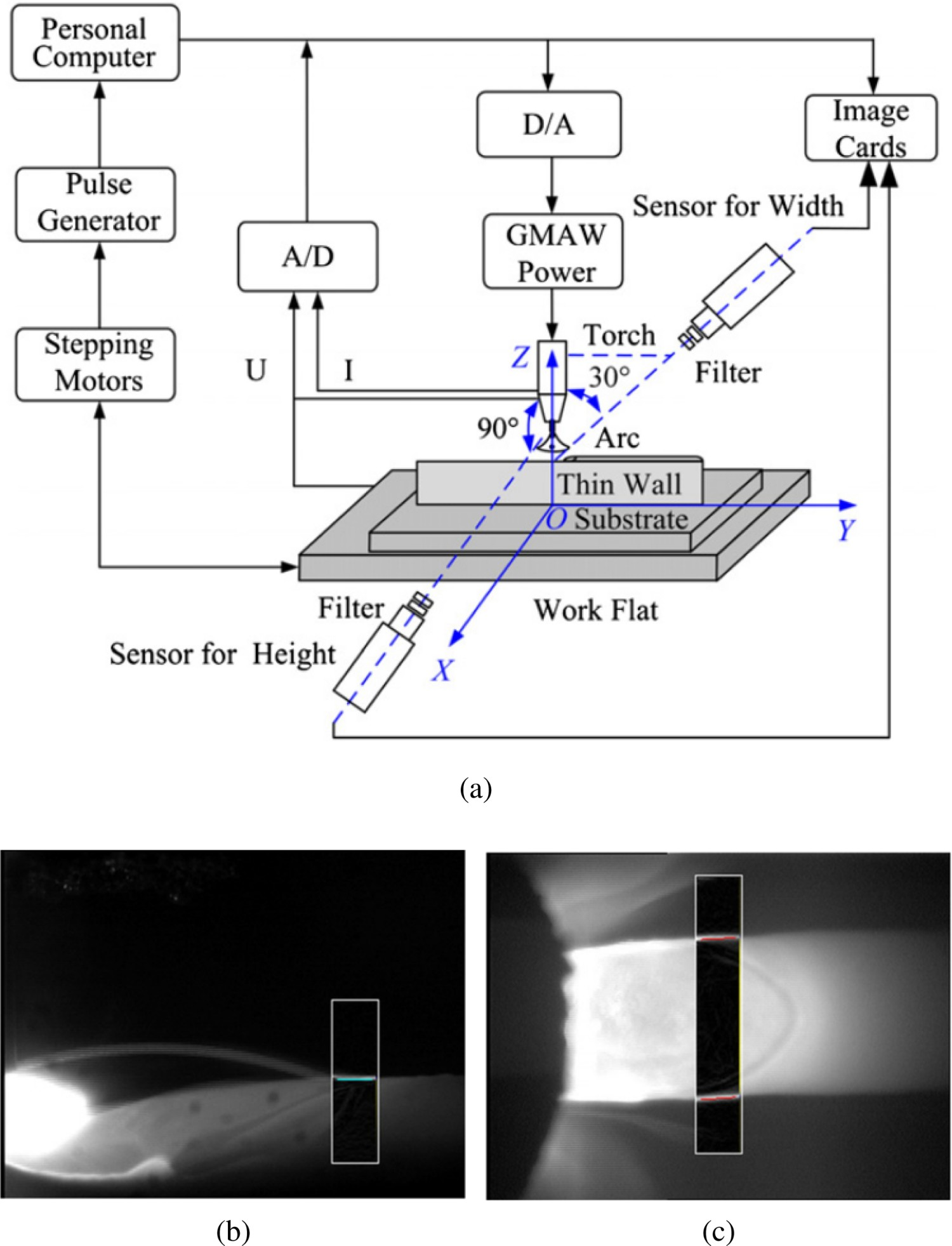
In a further application of the vision-based bead geometry measurement method introduced in [329], Xiong and Zhang propose a controller for layer height control [334]. This control algorithm – an adaptive, model-based controller – takes the measured bead height as feedback and adjusts the deposition rate to achieve a constant nozzle standoff distance and, by extension, a constant bead height. The adaptive component of the controller is based on a delayed first-order model and a controlled autoregressive moving average model to describe the relationship between deposition rate as input and nozzle standoff distance as output. The control system is comprised of two loops: an inner loop for conventional feedback control of the nozzle standoff distance and an outer loop for online identification of the process parameters and adjustment of the inner loop controller parameters. Noted bead height disturbances result from inter-layer temperature and shape fluctuations of previous layers due to heat accumulation. It is shown experimentally that the control algorithm maintains an accuracy of 
In a further study, Xiong et al. used their previously developed vision-based bead geometry sensing system combined with their previously proposed segmented neuron self-learning PSD controller for adjusting the layer width [335]. The control variable in their scheme is the torch travel speed, and a first-order process model is considered. The experimentally verified range of layer width was 6–9 mm and a mean absolute error of 0.5 mm.
In order to address the issue of poor accuracy when depositing beads with sharp corners, Li et al. also proposed an adaptive process control scheme capable of guaranteeing a uniform bead morphology during WAAM. In their scheme, the tool path is divided into several segments at sharp corners [285]. For each segment, a permissible travel speed, subjected to the dynamic constraint, is selected, and the wire-feed speed is set beforehand according to a process model. In this method, matching the travel speed and the wire-feed rate leads to a uniform bead morphology among different segments.
Many of the above-reviewed control schemes use models for adaptive control of the various geometric features of the bead. Models that can be used in real-time to predict the bead geometry and related factors are important for adaptive and robust control schemes. As a requirement, these models must supply prediction updates at high sampling rates. Some suitable modelling methods for real-time control are reviewed next. Pal et al. developed models for the prediction of the bead geometry using a Back Propagation Neural Network (BPNN) model, a Radial Basis Function Network (RBFN) model, as well as a regression model [336]. The bead width and height were predicted as a function of process parameters, including pulse voltage, background voltage, pulse duration, pulse frequency, wire feed rate, and RMS welding voltage and current. Akkas et al. designed an Artificial Neural Network (ANN) and neuro-fuzzy system for predicting the bead thickness and penetration area while providing the three welding parameters of voltage, current, and speed [337]. Ding et al. trained an ANN model to specify welding parameters according to the bead width and height during WAAM applications [324]. Li et al. proposed a predictive ANN for specifying the offset distance of the beads in order to control the real center distance of the side-by-side beads according to the desired values of bead width, height, and the center distance between the beads for the WAAM process [338]. Ríos et al. presented an analytical process model which correlates layer width and height with the WAAM process parameters [320].
The limitation of camera systems such as the one introduced in [329] is that the measurements are obtained at a low sampling rate due to the need for computationally intensive image data processing. A further drawback caused by the increased processing time is a significant measurement time delay, which is not feasible for fast-response control algorithms. Profilometers are much more suitable for bead geometry measurement since the bead geometry is detected directly and does not have to be extracted from the pixel data of an image, thus increasing the sampling rate. They can also provide a 3D profile of the bead at higher resolution, which improves the accuracy of prediction algorithms that use historical data to make predictions. Many of the reviewed control algorithms that use cameras for feedback (e.g. [333, 334]) could obtain the same feedback information from profilometers at a higher sampling rate, possibly resulting in a more responsive and accurate controller design.
As each layer is typically comprised of deposited beads, defects can be caused by inadequate process planning, such as inaccuracies in the overlapping model, voids caused by the path planning algorithm, parameter uncertainty, and deviations in deposition caused by the dynamics of the robotic system. Therefore, besides measuring and controlling the bead geometry, it is important to monitor the adherence of each printed layer surface geometry to the desired geometry determined during process planning and to ensure that voids and other defects are mitigated by modification of the subsequent layer's tool path. A 3D laser scanner can obtain a point cloud of the surface geometry of a deposited layer.
In order to mitigate accumulating deviations of layer surface geometry during a print using a wire-fed LDED system, Heralic et al. developed a method for obtaining a 3D point-cloud of the layer surface geometry by moving a profilometer across the part after the completion of each layer [321]. 3D point cloud data was used to control the layer height during the print using an iterative learning controller (ILC). A comparison between an open-loop (without deviation feedback) and closed-loop (with deviation feedback) part print shows that the ILC can suppress deviations that would lead to a failed print during open-loop printing. The authors acknowledge that some issues exist with their used profilometer model as it was not designed for welding applications.
Also, to detect deviations from a desired layer surface geometry, Preissler et al. devised a stereoscopic camera system using the pattern projection method for polymer AM to obtain a 3D point cloud from a top-down perspective of the layer surface geometry after the completion of each layer [325]. Although the system is developed for polymer AM, the same proposed method is also fundamentally suitable for metal AM. Preissler et al. then used their developed 3D scanner to compare the desired surface geometry of the current layer to the measured layer surface geometry [326]. The 3D point cloud data is sufficiently accurate to detect deviations of 0.5% that can lead to a manufacturing failure.
Melt pool temperature and geometry
The primary devices used for monitoring the melt pool temperature and geometry are pyrometers, IR, CCD and CMOS cameras. The temperature and geometrical features of the melt pool could be used as inputs to a predictive system, such as an artificial neural network, to specify bead width and height, providing predictions for model-based predictive controllers. In addition, thermal maps obtained from IR cameras may be used for monitoring thermal dissipation, temperature gradients, and thermal cycles throughout the build and the melt pool geometry [48, 182, 183]. In this section, various proposed measurement systems and control methods that use thermal and geometrical measurements for feedback are reviewed for various deposition technologies. First, the literature on LDED is reviewed, followed by the literature on arc-based deposition methods (e.g. GMAW, GTAW).
A method for the temperature-based measurement of the melt pool size in powder-fed LDED using a CCD camera equipped with a narrow-band IR filter was introduced by Hu and Kovacevic [339]. The laser power and, therefore, the melt pool temperature was controlled in order to control the bead width by adjusting the size of the melt pool. Experimental results showed that it is possible to effectively control the temperature of the processing zone by adjusting the width of the melt pool by controlling the heat input and metal powder feed.
Bi et al. proposed in 2006 the first thorough study on the feasibility of various in-situ measurement systems for LDED, such as a photodiode and quotient pyrometer temperature control system (TCS) to measure the temperature [340]. The deposition head is shown in Figure 19. Moreover, a CCD camera, which was coaxially aligned with the laser beam through mirrors, measured the size of the melt pool during powder-fed LDED. The introduced methods were verified experimentally to be suitable for temperature control. Furthermore, the influence of process parameters such as laser power on the temperature signal was investigated. Through adjusting multiple process parameters such as deposition head travel speed, material (powder) feed rate, and laser power, it was found that the laser power shows the strongest influence on the IR temperature signal. Based on the results obtained in the previous work, Bi et al. then proposed a closed-loop proportional-integral-derivative (PID) controller taking temperature feedback from a pyrometer to control the melt pool temperature [341]. The proposed controller was able to increase the dimensional accuracy of single-track, multi-layered walls. Bi et al. then further proposed a compact laser cladding head with integrated temperature sensors as previously proposed in [340] including a Germanium (Ge) photodiode for measuring the melt pool temperature and a CCD camera for monitoring the melt pool geometry [342]. A PID controller was used to keep the melt pool temperature constant by adjusting the laser power. The authors were able to significantly improve the quality of an additively manufactured airfoil by minimizing the accumulated temperature through their temperature control system. Tang and Landers proposed a melt pool model based on a first-order transfer function for LDED [343]. It was found that previously proposed models were not suitable for online temperature control due to their complexity. A digital tracking controller was designed to control the process quality via a Kalman-filtered feedback of a temperature sensor. However, it was concluded that the controller might not perform well with multi-layer depositions due to heat transfer issues. To further improve the laser cladding process to facilitate adoption in the industry, Bi et al. identified key factors influencing process monitoring and control in laser-based DED [344]. A single-color pyrometer was integrated with a powder feeding nozzle to monitor melt pool temperature to identify influencing factors. Geometry, power density, and oxidation were identified as affecting the process control performance. Nassar et al. presented a closed-loop control architecture for controlling the path plan during LDED to optimize the build microstructure. A temperature-based controller was implemented [322]. An application of in-situ temperature sensing for control of the solidification rate and, therefore, the microstructure during powder-fed LDED was proposed by Farshidianfar et al.[345]. Using a CCD camera equipped with an IR filter to observe the melt pool and solidification area, the temperature gradient of the solidification area after the melt pool was obtained. The authors then proposed a PID-based controller for regulating the cooling rate, and therefore the microstructure, via adjustment of the deposition head travel speed. It was shown experimentally that the microstructure remained consistent due to the controlled cooling rate.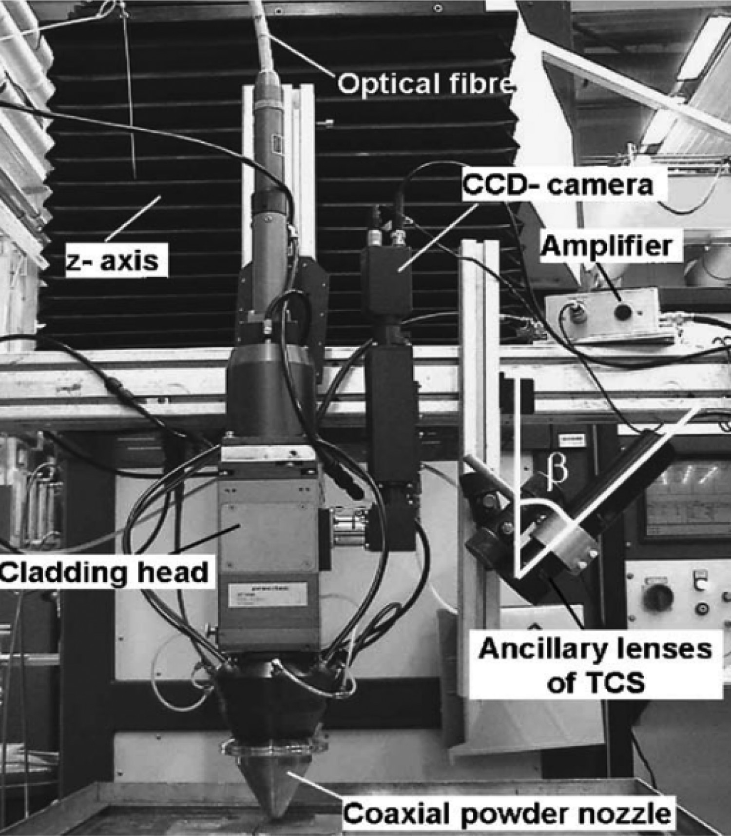
Doumanidis and Hardt proposed a multi-variable adaptive closed-loop controller using temperature feedback of heat affected zone in arc welding [346]. They considered a structured heat model with uncertain parameters. In addition to the layer geometry sensing via profilometer described in Section 5.1 for wire-and-arc welding, Doumanidis and Kwak also used an infrared camera to measure the temperature and geometry of the melt pool [331]. The in-situ melt pool measurements were then used to identify the parameters of a lumped-parameter model for the melt pool that models the relationship between its geometrical and thermal properties and the process parameters, including torch power, material feed, torch angle, and motion. This model was then utilized for real-time bead geometry control. In order to overcome sensory delay, a Smith predictor was used. The overall RMS error between the desired and achieved layer geometry was 0.23 mm. Wu et al. also utilized a CCD camera in combination with a narrow-band IR filter to construct a passive vision sensing system for imaging the weld pool during constant-current GTAW [347]. The images were then processed to obtain the melt pool size. Lü et al. proposed a multiple-input single-output (MISO) adaptive controller for adjusting the width of the weld pool during GTAW utilizing feedback of wire feed rate, welding current, and topside image of the weld pool [330]. A backpropagation neural network (BPNN) model was used to estimate the backside pool width and compared it with the desired value. Xu et al. focused on two issues in their study on GTAW and GMAW: capturing a clear weld image and developing an image processing technique for feature extraction [323]. For the former, a novel passive vision system taking advantage of a CCD camera with a moveable motorized filter, which could cross out disturbances of the arc light during seam tracking, was proposed. For the latter, image processing algorithms encompassing restoration, smoothing, edge detection, false edge removal and edge scan were developed. Babkin and Gladkov introduced a new graphical method for GMAW welding parameter determination [348]. The influence of the workpiece temperature control over the geometrical preciseness of the deposited layer was highlighted. Feng et al. used a CCD camera to monitor the weld pool surface in GTAW [349]. The contribution was to compute the height of the mirror-like bead surface via processing of the reflection image of the reversed electrode on the bead surface, knowing its constant tip-to-workpiece distance.
As mentioned above, the microstructure is highly dependent on the local cooling rate the part experiences during deposition. Processing parameters, such as travel speed, dwell time, material feed rate and travel direction, affect the solidification velocity and the resulting crystalline morphology [351]. The layer-by-layer variance in processing conditions results in non-uniform and transient temperature gradients throughout the build, leading to an anisotropic microstructure [58]. Thus the mechanical properties have a directional dependency, which is undesirable for many applications. Heat treatment is used to manipulate and control the final microstructure, ensuring optimum performance when the final part is placed in service.
One of the more important heat-treating processes for AM is annealing, where the material is held at elevated temperatures for extended periods of time and then cooled at various rates. The different annealing treatments for AM deposits are shown in Figure 20. Residual stresses result from the unique thermal cycling that occurs during the AM deposition process [353]. Low-temperature annealing (T1 in Figure 20) improves atomic diffusion, allowing for dislocation motion and annihilation, relieving some of the induced thermal stresses. The significant strain induced by residual stresses can provide the driving force for the nucleation and growth of stress-free equiaxed grains, further reducing the internal stress. This phenomenon is known as recrystallization and has also been observed when stress relieving AM deposits [354]. Increasing the annealing temperature (T2 in Figure 20) to a point where all elemental constituents are dissolved in a single solid phase is known as a solution annealing heat treatment. The deposit is then quenched to prevent any diffusion or phase formation, resulting in a supersaturated solid phase. This is followed by a precipitation heat treatment, also referred to as aging, where the deposit is heated to a temperature (T3 in Figure 20) where diffusion is energetically favourable. This results in the nucleation of finely dispersed precipitates, or the formation of desirable secondary phases, improving the mechanical performance [352]. This section will outline the different heat treatments that are common for the materials discussed in 2.4. First, the conventional heat treatments will be discussed where applicable to outline each heat treatment step's purpose and give insights on how heat-treating AM parts may result in different microstructures with the same heat treatment. This will lead to the as-built microstructure for each material when using different heat sources. Then a general overview on what heat treatments have been done by other researchers, and how it changes the as-built microstructure and corresponding performance will be discussed. It should be noted that the scope of this section is limited to studies on DED. The materials that require further investigation will be identified. Furthermore, the heat treatments presented are generalized to highlight the effects the different heat treatments have on microstructure and mechanical performance. Thus details including temperature, hold times and cooling rates may not be mentioned. Finally, any mention of an aging process is done post solutionizing and not to the as-built structure due to the limited researchers utilizing a direct aging process directly after printing. This is thought to be attributed to the anisotropic microstructure of the as-built parts. Although there is an extended solid solution due to the rapid solidification, the nucleation of precipitates would not be homogeneously distributed throughout the part. Therefore, the mechanical properties would still be directionally dependent. A re-imagining from [352]. The different thermal cycles for the heat treatments typically conducted on AM deposits, where the red solid line represents the solution annealing, the blue dotted line represents precipitation hardening, and the yellow dashed line represents stress relieving heat treatments. Note that T1, T2 and T3, as well as the hold times, heating and cooling rates are material specific, and the depicted plots are not accurate representations.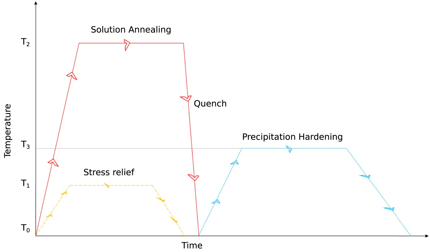
The scope of this section is limited to Ti–6Al–4V (Ti64) due to the abundance of studies conducted on this material system. There are other Ti alloys that are being studied, such as TC21 [64, 235, 237, 355–357], near β Ti alloys [358–361] and near α Ti alloys [362], but they will not specifically be mentioned.
The heat treatment of Ti64 typically includes solution annealing and aging at a range of temperatures depending on the desired mechanical properties. Typically, the solution temperature is below the β transus temperature [363]. Lower annealing temperatures result in mostly α, with some β at the grain boundaries. The higher the annealing temperature, the higher the fraction of β that will form upon cooling. However, there is a decrease in solubility of V as the temperature increases, causing the β phase to turn to α' with quenching. If any β is retained after solution treatment at higher temperatures, a martensitic transformation to α' will be induced when plastically deformed [364]. Higher cooling rates are more desirable for Ti64 to maximize the amount of supersaturated β or α', which can be decomposed to α precipitates during aging [363, 365].
Laser-based AM techniques result in a mix of columnar and equiaxed grain morphologies, depending on the thermal history of the part. Equiaxed grains tend to form closer to the edges due to the higher thermal gradient achieved at these locations [57, 58, 64, 236]. The microstructure consists of primary β with α lamellae, which form in colonies, Widmanstätten or basketweave morphology. These colonies are more prevalent along prior β grain boundaries and close to the β transus lines from the interlayer passes. This microstructure has been seen for both powder and wire fed processes [57, 60, 62, 64, 93–96, 133]. Electron beam and plasma techniques have also shown to have similar microstructures, with martensitic α' and α laths in a Widmanstätten or basketweave morphology, and a small amount of acicular α [110, 113, 114, 150, 151, 158, 161]. Defects such as pores are also prevalent in the as-built parts that cannot be removed with standard heat treatment methods [60, 366–368]. Lower annealing temperatures tend to lead to coarsening of the α laths to more plate-like morphology, with interplate transformed β [93, 95]. The α plates transform into ‘crab-like’ morphology closer to the β transus temperature [64]. Furthermore, recrystallization of β grains begins at higher solution temperatures, while the primary α laths increase in aspect ratio and decrease in volume percent. The formation of β with solution treatment has been shown to increase the corrosion resistance of AM Ti64 parts. The coarsening of the α laths decreases strength while increasing the elongation [62, 369]. Increasing the annealing time decreases the aspect ratio of the α phase while also inducing a higher amount of precipitation of secondary α in the retained β phase [57, 158]. This causes an initial spike in strength, but this decreases as the secondary α coarsens. Increasing aging times decreases the volume fraction and aspect ratios of primary α laths while increasing the volume fraction of fine secondary α. Increasing aging time slightly coarsens the secondary α but decreases the width of the primary α, causing slight increases in the strength and ductility. Aging times over 8 h will result in the globularization of the α laths. These precipitates tend to coarsen with higher subsequent aging temperatures [62]. Heat treatment has shown to reduce hardness due to grain coarsening and dislocation annihilation [64]. Under dynamic loading, heat treatment may reduce strain rate sensitivity while increasing the risks of adiabatic shear localization [57].
Ni alloys
This section will discuss the heat treatment protocols of both Inconel 718 and Inconel 625. A summary of the standard heat treatment and corresponding microstructure will be presented for each material, followed by a tabular summary of the effects of heat treatment on mechanical performance.
Inconel 718
Heat treatments for industrial casting and forging operations of In718 follow solution treatment and age protocol outlined in AMS-5383D [370], and a solution treatment and aging protocol discussed in AMS-5662M [371], respectively. The high-temperature mechanical properties of In718 are attributed to the precipitation of the γ”( A comparison of the mechanical properties: (a) yield strength, (b) ultimate tensitle strength and (c) elongation of heat treated In718 alloys produced by conventional manufacturing methods (wrought and cast) and AM methods (DLD, DEBD, SLM, and EBM) [381].


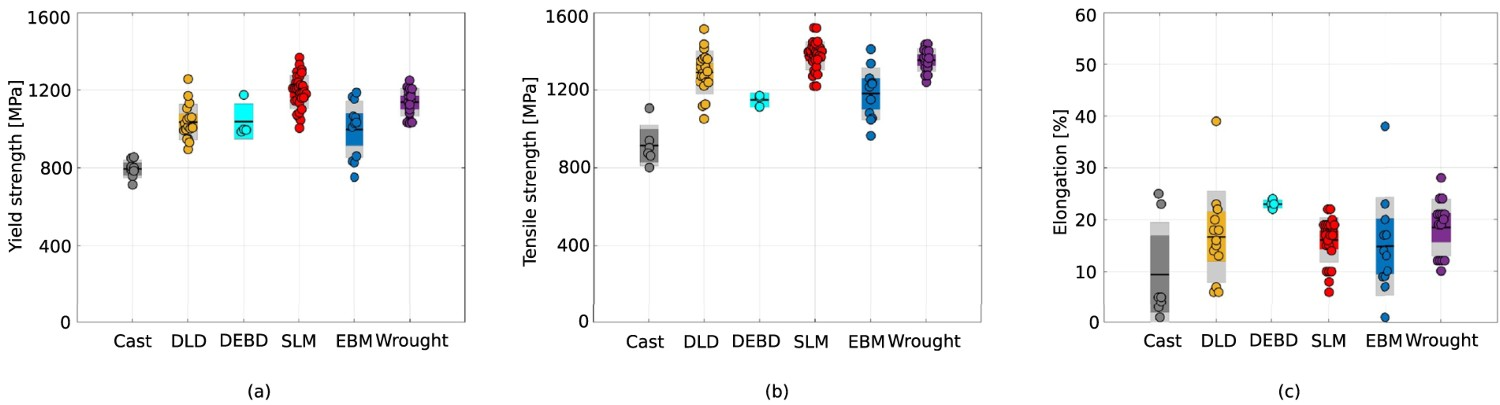
The macrostructure of as-built In625 produced by AM is a range between cellular and columnar dendrites, depending on the specific thermal history of that region [122, 382]. The columnar dendritic structure has been seen to be stable up in heat treatments up to 


Steels
This section will discuss the post-processing of 316L and 17-4 stainless steel. This will include the microstructural changes from the as-built condition with heat treatment and the corresponding changes to the mechanical properties.
316L stainless steel
AM of 316L typically results in an ultra-fine and cellular columnar dendritic grain structure due to the rapid cooling rates experienced during the building process [388, 389]. There have also been reports of large amounts of anisotropic crystal orientations and grain sizes in 316L deposits from the complex thermal cycling seen in all AM techniques [390, 391]. A common defect is silicide, and oxide inclusions, which is attributed to possible oxygen contamination in the feedstock, or during the building process [388, 390, 392]. Pores are also a common defect found in AM deposits of 316L, which are detrimental to the mechanical properties and corrosion resistance [389, 393]. Saeidi et al. found when using a laser-based AM technique that the single-phase FCC austenitic structure seen in the powdered feedstock is mostly conserved in the as-built condition, with varying amounts of BCC ferrite. Sub-grain boundaries were found to be enriched in alloying elements such as Ni and Mo [390, 391, 393, 394]. Plasma AM methods typically resulted in columnar structures of austenite (γ) of varying coarseness depending upon the location with respect to the fusion line. The inter-columnar area consisted of vermicular δ ferrite and σ (FeCr)intermetallic at the 


17-4 PH stainless steel
The industrial standard heat treatment of 17-4 PH hot-rolled and cold-finished product follows ASTM A564/A564M. This standard outlines a solution treatment of 

Al alloys
The post-fabrication heat treatment discussed in this section will be limited to the hypo-eutectic alloy AlSi10Mg, as it is the most studied of the Al alloys. An outline of the standard heat treatment will be reviewed, followed by the as-built and post heat treatment microstructure, and the corresponding effect on mechanical properties.
The typical heat treatment for Al–Si alloys is a T6 treatment, which is a solution heat treatment at 535


Co–Cr alloys
This section will discuss the heat treatment of AM deposited Co–Cr alloys. The focus will be on Stellite 21 and Stellite 6 Co–Cr–Mo alloys, as they are the most studied. An outline of the standard heat treatment will be reviewed, followed by the as-built and post heat treatment microstructure, and the corresponding effect on mechanical properties.
For cast Co–Cr–Mo alloys complying with ASTM F75, no standard heat treatment is included [417]. The as-cast condition of this composition typically consists of FCC γ Co, a σ intermetallic, and 


Mg alloys
The use of Mg alloys for AM has not been explored in as much depth as the other alloys presented in this work. Thus no work has been published on the effects of heat treatment on the microstructure and corresponding properties of Mg deposits.
Copper alloys
The majority of the work on Cu alloys for DED technologies has been on WAAM of nickel aluminium bronze. Shen et al.deposited nickel aluminium bronze using WAAM and found that the as-built microstructure mainly consisted of Widmanstätten α phase and martensitic β phase [126, 127, 428]. Dharmendra et al. found no retained β, but instead found 

Tungsten alloys
As mentioned previously, some work has been done on DED of pure W [431], W-Ni alloys [90], W-Fe alloys [432] and tungsten heavy alloys [89]. However, no work has been conducted on how post-processing affects the microstructure and the corresponding properties.
Challenges and future perspectives
This work provides a holistic overview of the current state of the art in large scale robotic AM, from process planning to the microstructure and performance of the final component. Although the contributions made by the many researchers in progressing this field have been substantial in the last few decades, the technology is still in its infancy. Dr. Hannes Gostner compared AM to celestial observation at the 2019 Holistic Innovation in Additive Manufacturing (HI-AM) conference in Vancouver. He stated that AM is currently in the technological stage of Galileo's telescope and that the capabilities have the potential to be as revolutionary as the Hubble telescope. However, the boulder has a long way to be pushed before the innovative pinnacle can be crested. The lack of the field's maturity is also evident from the lack of finalized qualification and certification standards (see Table 1). The majority of the standards listed in Table 1 are currently still in draft status. Robotic large-scale AM as a sub-category within AM as a whole is highly interdisciplinary–like any other groundbreaking and paradigm-shifting endeavour. The major engineering and science disciplines involved in large-scale robotic metal AM include computer science, electrical engineering (mechatronics-, control- and systems engineering), materials engineering, and mechanical engineering. In addition, each of the process workflow stages as outlined in Figure 3 are also highly coupled. For example, a process plan consisting of a deposition system motion sequence and parameters generated by the process planning stage will affect the thermal distribution, which will affect the amount of residual stress and heat accumulation, and microstructure and corresponding mechanical properties.
Naturally, computer scientists, mechatronics-, control- and systems engineers are predominantly concerned with issues relating to their particular domains and can not necessarily appreciate the coupled challenges faced by materials-, and mechanical engineers. Therefore, a close and direct collaboration between diverse research groups is required to progress this technology further. Extensive collaboration and sharing of information will result in more holistic studies on, for example, how different path planning strategies affect the surface roughness and microstructure of an as-built component. This will give rise to new information on the different strategies that can be implemented to solve the current challenges, such as residual stress, porosity and anisotropic microstructures. This need for collaboration has already been recognized, which has resulted in the creation of networks such as the NSERC Holistic Innovation in Additive Manufacturing (HI-AM), America Makes, and others. However, the lack of research-level fabrication of large-scale parts makes it hard to fully understand the challenges that will need to be overcome to make this a viable commercial process. It is currently speculated that overcoming the current challenges of fabricating lab-scale coupons will translate to large-scale parts. The true challenges that lie ahead for large-scale AM will not be revealed until more researchers begin to fabricate parts outside of a lab setting.
This section summarizes and discusses the largest knowledge gaps in the topics outlined in Section 2 to Section 6, followed by a holistic view of the challenges that must be overcome to commercialize large scale AM. The subsections will be structured where the challenges of each topic will be addressed, followed by the authors' suggestions on the future of research areas pertaining to the topic.
Process planning
Current path planning methods are generally limited to 2.5 DOF, with few systems available for 3–5 DOF path planning. 2.5 DOF systems are inherently inefficient due to support structures, requiring post-processing as well as design limitations. For large-scale parts, this entails additional manufacturing costs (such as labour and delivery time). 5 DOF path planning overcomes these challenges to a large extent but has limited industrial integration. A number of algorithms have been reviewed in this paper. While the algorithms are fundamentally suitable for metal AM, work is still required on non-planar tool path planning for metal AM where the generated tool path must satisfy the requirements identified in Section 4.2. Adaptive slicing offers an advantage in terms of reducing both the layer height and variation in material properties. This necessitates a fundamental understanding of bead deposition geometry, microstructure and solidification modelling. Combining this knowledge with adaptive slicing will allow efficient manufacturing of high-quality parts, but this requires a significant multidisciplinary effort in material science and mechanical and manufacturing engineering. Path planning, which is a function of part geometry, directly affects heat transfer and conduction through the part being made. This results in varying amounts of additional heat in the part at any given time and build location, resulting in varying solidification rates, thereby affecting the geometry of the build and the resultant microstructure. Therefore, it is necessary to include heat transfer modelling at an earlier stage concurrent to the path planning. Current models suffer from long simulation times, inherent assumptions to reduce computational time, and a limited set of manufacturing systems and material system availability which need to be improved through further research.
Incorporation of multi-degree of freedom path planning along with considerations of the aspects mentioned above will enable in-situ modification of material metallurgy and its mechanical and geometric properties during deposition. This will truly unleash the potential freedom of design and complexity that AM processes have to offer.
Prior to fabrication, it is also necessary in many cases to calibrate the workpiece with the fabrication platform. This is especially important when the build requires coordinated motion between the workpiece and deposition system – as is always the case during multi-directional deposition. Workpiece calibration can be automated by using a 3D or line scanner mounted on the deposition head.
Deposition technologies
An area where considerable research potential can be found in the powder delivery during multi-axis DED (e.g. using an 8 DOF robotic LDED platform). Currently, the LDED deposition head must always remain vertical and thus align with the gravity vector to provide ideal powder delivery. Developing methods to loosen these constraints on the deposition head orientation is necessary to utilize the full potential of an 8 DOF robotic LDED platform. Several challenges need to be overcome to enable this, including, but not limited to, modelling of powder flow at different angles to the build surface and the effect of shielding gas dispersion in the build area at non-vertical angles.
While in contrast to LDED, deposition at varying orientations is intrinsically possible with fewer limitations using GMAW-based deposition technologies. However, they are at a stage of lower maturity regarding monitoring the melt pool temperature and geometry and energy input. Sensing the melt pool in a GMAW-based deposition system is also challenging due to the rapidly and drastically changing lighting conditions due to the presence of the arc.
Work is also ongoing on the minimization of the energy input during GMAW-based deposition, where CMT technology plays a significant role. Owing to the highly controlled CMT process where it is possible to fine-tune the deposition process, significant potential for the optimization and adaptation to particular material considerations is possible. For example, in recent years, Fronius International GmbH has been developing custom synergic lines to further reduce the heat input during WAAM using CMT technology [L. Hudson and M. Zablocki, personal email and oral communications, March 2020]. Further potential for advanced research on optimizing the deposition process exists and should be considered. This necessitates in-situ and high-speed sensing of the welding current and voltage, providing important insight into the energy input into the build during fabrication. It can also provide valuable insight into the process, and the measurements themselves can be used as feedback for temperature control systems. Moreover, tremendous potential for robust sensor-fusion-based technologies exists.
In-situ monitoring, modelling and control
The control algorithms reviewed in Section 5.1 for bead geometry control are relatively basic and have only been developed for and tested with single-track walls. Significant research is required to advance process monitoring and control towards the objective of robust, adaptive and intelligent control methods that provide a sufficient degree of autonomy and robustness to unanticipated conditions during fabrication. Moreover, bead profile sensing and feature extraction have only been done for simple beads. The sensing and feature extraction capabilities need to be expanded and combined with modelling to provide accurate predictions of single beads and overlapping regions of multi-track deposition.
Substantial research potential is also apparent for advancing the area of layer geometry sensing and tool path re-planning during fabrication. The fact that during fabrication, a component is built layer by layer provides a unique insight into the current state of the build through the methods reviewed in Section 5.2. Impending catastrophic build failures can be detected, and the tool path for the following layer can be re-planned to mitigate and correct potential build failures.
Most work on temperature monitoring, and control has been done for LDED, as is apparent from Section 5.3. Particularly melt pool temperature sensing needs substantial work for arc-based deposition technologies. Heat accumulation is coupled with the deposition system travel speed and the material feed rate, which influence the bead and layer geometry. This means that if the bead geometry is adjusted (which is necessary), the heat input changes, which can modify the material composition.
Similarly, as for the layer geometry monitoring, IR cameras can also monitor the overall surface temperature of the component during the build to adjust dwell times and cooling rate of the substrate plate. This is especially important for maintaining consistent metallurgical properties.
Materials
Many challenges still need to be addressed in regards to materials for AM. One of the more apparent areas of exploration is expanding the number of materials available in AM. This is clearly highlighted by the chart presented in Figure 22 [433]. Although many of the materials used in conventional manufacturing are ill-suited for AM, there are still important contributions that can be made through failed experimentation. Increasing the amount of data on what materials may or may not be compatible with AM, allows for significant deductions to be made on the essential material properties a material must have to be used in AM.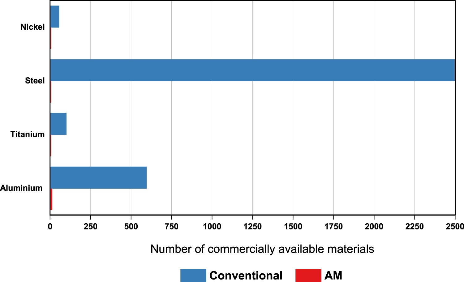
Another future avenue of interest is using AM to achieve manufacturing feats that are outside the realm of possibility with conventional manufacturing. Although metals toughness far exceeds any other type of material, this comes with a poor strength to weight ratio. However, with AM, the internal structure can be altered to a lattice type, drastically increasing the strength to weight ratio. Additionally, polymer-based AM techniques could be used to fabricate these structures, which can be converted to a mould, and then cast, known as hybrid investment casting. This allows for the use of well-understood material systems in the way they were originally designed.
One of the challenges that is starting to be addressed is the current material selection for AM [434]. The current materials landscape for AM is dominated by materials that were successful with conventional manufacturing techniques. These materials were not designed for the complex thermal cycling inherent to AM, which result in material defects and anisotropic microstructures. Thus the development of new materials created explicitly for AM could allow for more control over phase transformations, elemental segregation and the resulting microstructure. This is especially crucial for large components, where heat treatment procedures incur a financial cost that make them unfeasible compared to conventional manufacturing. Furthermore, microstructural control will allow for predictions in how the part will perform when in service, which is imperative for on-site fabrication. Some promising alternative methodologies are being explored to prevent the epitaxial growth of large columnar grains. The addition of inoculants to aid in the nucleation of equiaxed grains would eliminate anisotropic mechanical properties prevalent in a lot of AM deposits [435]. The addition of boron to Ti64 has been shown to form TiB, which allows for the nucleation of α-grains, resulting in an isotropic grain structure [436]. A similar phenomenon has been reported with the addition of Ti to 5356 Al [253]. Furthermore, the addition of carbon to Ti64's hypoeutectic composition decreases the solidification temperature, causing grain growth restriction through constitutional supercooling. Although a different mechanism, a similar isotropic grain structure occurred [437]. These studies highlight that the development of materials better suited for AM is going to involve understanding the fundamental material paradigms involved in grain growth and solidification, and how these can be used to manipulate the thermodynamics of the system, to mitigate some of the microstructural challenges that researchers are currently faced with. Large amounts of data can be compiled by completing the aforementioned experiments on increasing the materials being trialed for AM, trying completely new material compositions, and in-situ grain control, which can then be used as input for artificial neural networks, to synthesize new materials specifically for AM. This would also incorporate all the data from the published process planning and monitoring and control strategies, allowing the network to develop the appropriate deposition strategy for the new material. The seed to the network would be a material of known composition, as-built microstructure, and mechanical properties. The network would have the ability to simulate the deposition of the material and then predict its as-built microstructure and mechanical properties. The model would employ reinforcement learning strategies to iterate over various compositions of the material, based on the data acquired from the research, to optimize the microstructure and mechanical properties based on the part's specifications. This could completely reinvent how material selection is done and produce materials specifically tailored to the additive manufacturing of that specific part.
The materials available for large-scale robotic AM are currently limited to current alloys in either the welding or coating processes. Material development for various processes used in AM is in its infancy and will yield significant opportunities as the processes mature.
The complex thermal cycling of AM leads to microstructures that are not found in conventional casting and forging operations. Using design guidelines of traditional heat treatment protocols can result in poorer mechanical properties in some materials. This is attributed to the varying degrees of segregation or the novel grain structure that occurs during deposition [438]. Furthermore, many post-processing operations rely on HIPing to reduce internal porosity. This is problematic for large-scale AM due to the inherent cost of this procedure and the size of the processing chamber needed to contain the large part. Thus developing techniques to reduce porosity in situ will be an essential future contribution to AM. Furthermore, the poor geometric tolerance obtained from parts manufactured using particular metal DED systems will need to be improved to reduce the manufacturing costs. This problem currently necessitates hybrid manufacturing systems or some combination of additive and subtractive technologies. This requires developing frameworks that unify positioning, referencing, and planning software to negate the need to detach the part from the build plate and any post-processing. The framework would also need to include localized heat treatment and a means to control the whole part's thermal cycle to ensure the promised mechanical performance. Thus it is speculated that the next generation of large-scale AM systems will appear more similar to traditional manufacturing approaches than powder bed fusion systems. There will be some modularity, where the part will be fabricated and machined in one module and then transferred automatically to a separate heat treatment module, similar to what is seen in traditional manufacturing. It is clear that an integrated automation system will increase productivity for this type of manufacturing. However, this manufacturing system would offer the geometrical freedom and the multi-meter scalability that both traditional and PBF are unable to provide.
The challenge remains to identify the raw materials, process conditions, and process control to maximize product quality using the AM processes and minimize subsequent post-processing requirements. The novel solutions will only be met through multidisciplinary and cross-functional teams closely collaborating. For example, this paper could not have been written without the close collaboration between mechanical, process control, mechatronics, electrical and materials engineers. The future young engineers trained in AM will require a holistic knowledge base and the ability to work cooperatively with other disciplines in engineering, sciences, design and visual arts. This paper has intentionally not addressed the redesign of components from both an engineering or artistic design approach. However, the possibilities using AM technologies will reveal new opportunities that are currently not imaginable.
Footnotes
Acknowledgments
This work would not be possible without the financial aid from the Syncrude-NSERC CRD (CRDPJ 514752-17), Mitacs (MITACS MA IT11329) and HI-AM (NSERC HI-AM NETGP 494158), as well as the in-kind contribution and resources given by Innotech Alberta. The authors would like to thank Stefano Chiovelli for his support and adding an industrial perspective to the paper.
Disclosure statement
No potential conflict of interest was reported by the author(s).
References
