
Abstract
The fibre–matrix interface represents a vital element in the development and characterisation of fibre-reinforced polymers (FRPs). Extensive ranges of interfacial properties exist for different composite systems, measured with various interface characterisation techniques. However, the discrepancies in interfacial properties of similar fibre–matrix systems have not been fully addressed or explained. In this review, first, the interface-forming mechanisms of FRPs are established. Following a discourse on three primary factors that affect the fibre–matrix interface, the four main interface characterisation methods (single-fibre fragmentation, single-fibre pull-out, microbond and fibre push-in/-out tests) are described and critically reviewed. These sections review various detailed data reduction schemes, numerical approaches, accompanying challenges and sources of reported scatter. Finally, following the assessment of several infrequent test methods, comprehensive conclusions, prospective directions and intriguing extensions to the field are provided.
Introduction
The high stiffness, strength and low density of fibre-reinforced polymers (FRPs) make them an exceptional choice for lightweight structural components and a part of the solution for resolving the climate crisis. FRPs are highly tailorable: they can yield different mechanical behaviours by adjusting, for instance, their fibre type, orientation or volume fraction. The most common reinforcing fibres are carbon (CF), glass (GF) and natural fibres, and the most frequent matrices are polyester and epoxy (thermoset), and thermoplastics such as polypropylene (PP), polyamide (PA), polycarbonate (PC) and high-temperature thermoplastics such as polyether ether ketone (PEEK) and polyetherimide (PEI). The fibre–matrix interface plays a crucial role in the mechanical properties of FRPs since the stress is transferred between these two components through their interface. Achieving superior load transfer efficiency and mechanical properties is contingent upon establishing strong compatibility between the fibre and matrix at the interface. Several methods, such as interfacial adhesion modifiers, coatings and surface treatments, are employed to improve interfacial bonding in FRPs. These methods improve one or more of the six main mechanisms to form an interface in FRPs (see Figure 1). The six main mechanisms to form a fibre–matrix interface: (a) molecular entanglement, (b) inter-diffusion of elements, (c) electrostatic attraction, (d) chemical reaction between groups on reinforcement and matrix surfaces, (e) chemical reaction forming of a new compound, particularly in metal matrix composite, and (f) mechanical interlocking (redrawn from [1]).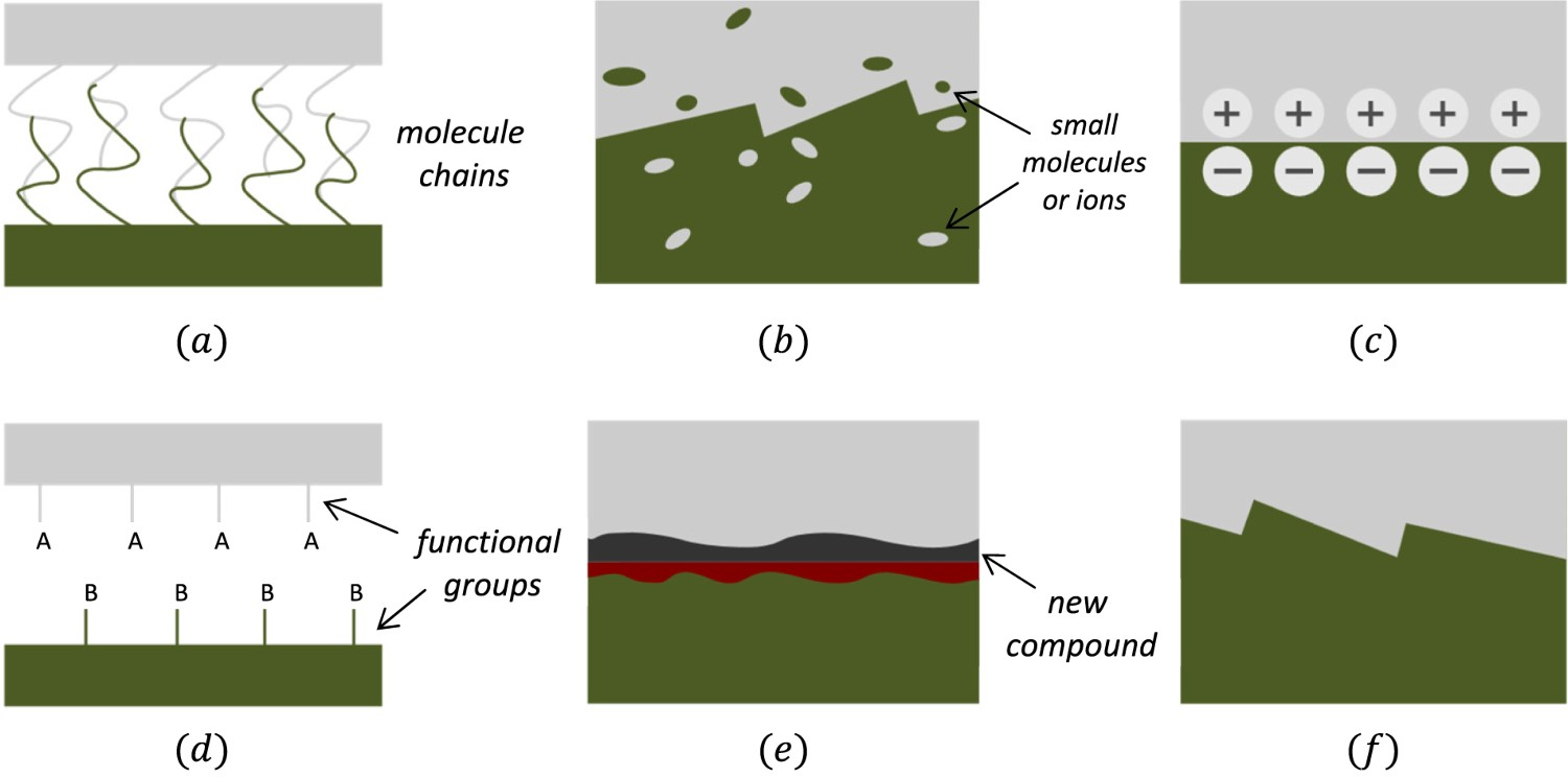
In the interaction between fibre and matrix, an intricate situation develops in which a third phase is thought to exist. This third phase extends between the fibre and matrix, known as the interphase (see Figure 2a), and results from physicochemical interactions between the constituents. In this 3D region, the matrix molecules have a constrained degree of freedom to polymerise [2]. As a result of these restrictions, the interphase material can be perceived as a region with varying properties (from those of fibre and matrix) [2]. Within the interphase, Nath et al. [2] suggested a quadratic variation of the elastic modulus and Poisson's ratio as a function of radial distance from the fibre axis. On the other hand, the interface is a 2D surface that forms around the fibre, where it comes in contact with the matrix.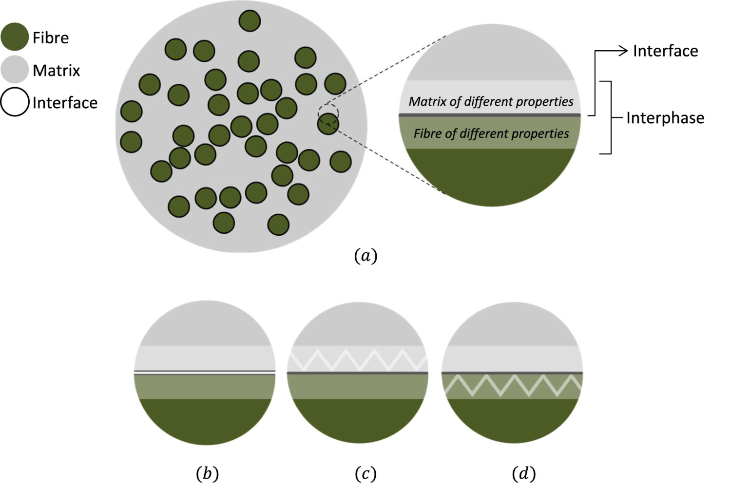
The properties of FRP constituents do not always translate into expected performance in manufactured FRPs [5–7]. The bond between fibres and matrix is regarded as the heart of FRPs. Thus ensuring good bonding between them is crucial. For instance, fibre surface modification can lead to improved intra- and interlaminar crack resistance of novel FRPs [8,9]. The quality of the bond also affects other macroscopic interface-reliant properties of the composite, such as its shear strength [10], compressive strength [11], translaminar fracture toughness [12], transverse strength, response to environmental exposure (such as aqueous or corrosive) and its impact performance [13]. The interface/interphase is subjected to a complex force field, and its failure will be determined by the applied stress tensor, as well as the chemical or mechanical affinity of the two phases (fibre and matrix). Debonding reduces the load-bearing capability of the composites. Interphasial failure modes can be categorised into three types based on the failure location: interface failure, failure in the modified reinforcement or failure in the modified matrix, as shown in Figure 2(b–d) (apart from matrix or fibre failure out of the interphase region). These failure modes can occur separately or simultaneously depending on the bond, fibre or matrix shear strength [1]. The experimental methods for characterising the fibre–matrix adhesion are agnostic on the difference between interface and 3D interphase. However, none of the major models that are used for data reduction explicitly incorporate the interphase. We will, therefore, mainly be referring to interfacial failure in the rest of this review article.
The mechanical tests for interface characterisation in FRPs, depending on the testing scale, can be classified into three categories: Nanoscale: These measurements are typically carried out by pulling out a nanofibre (for instance, on carbon nanotubes) or nanoparticle by the probe in a scanning probe microscope or atomic force microscope [4]. Microscale: Following the micromechanical models, direct micromechanical tests were developed to characterise the interface through debonding the (microscale) fibre from the matrix. The main microscale tests are the single-fibre fragmentation test, single-fibre pull-out test, microbond test and fibre push-in/-out test. Macroscale: Macroscale mechanical evaluations for laminated or filament wound FRPs include indirect test methods such as short beam shear test (ASTM D2344 [14]/ISO 14130 [15]), transverse flexure test (ASTM D7264 [16]/ISO 14125 [17]), fibre bundle pull-out (using fibre bundles instead of a single fibre) [18] and transverse fibre bundle tensile (TFBT) and 45° fibre bundle tensile (45FBT) tests [19,20].
The nanoscale tests are not relevant for typical fibres in FRPs. These tests do not provide direct results on the interface since the microlevel heterogeneity of FRPs complicates the measurement of their microscale properties via a macrolevel test. This makes macroscale tests more suitable for relative comparisons than for absolute measurements of interface properties. Thus this review only considers the microscale methods. The micromechanical models enable the deconstruction of the macroscale behaviour into simpler fibre–matrix interactions. However, the interfacial debonding models require demanding inputs: interfacial shear strength (IFSS) and interfacial fracture toughness (IFFT). The normal interfacial strength is somewhat less studied since mode II is frequently the dominant failure mode (for studied CF/GF-epoxy systems) [21]. To clarify, fracture toughness is typically expressed in MPa 
Fibre–matrix interfacial characterisation still poses some challenges from both practical and theoretical aspects. The laborious manufacturing process involves the manipulation of individual thin fibres, requires specific test setups and sometimes uses non-standardised test methods. Additionally, there are theoretical disputes over parameter selection and data reduction approaches for extracting interface parameters from the test data [24]. In the early 1990s, a round-robin exercise on micromechanical tests to measure the IFSS [25] reported an acceptable scatter within each laboratory but a high degree of inter-laboratory scatter for a specific test and material. This highlighted the demand for improved and unified data reduction and standardisation schemes.
To characterise the interface, direct or indirect observation methods can be exploited, including scanning electron microscopy (SEM), transmission electron microscopy and Fourier-transform infrared spectroscopy. These tools can provide a morphological/structural or chemical interfacial bond analysis and therefore are beneficial for understanding the interface forming mechanisms from a physical or physicochemical viewpoint. Fibre diameter, 
Overall, the fibre–matrix interface characterisation in FRPs is a complex and multi-faceted task requiring various experimental techniques and analytical methods. Some of the critical parameters that need to be measured in the fibre–matrix interface characterisation of FRPs include: IFSS, IFFT and interfacial friction coefficient (
The analysis of the bibliographic data in Web of Science shows that the share of the publications on the interface in FRPs field per year, complying with the search criteria ‘(composite*, carbon fib*/glass fib*, matrix/epoxy/thermoplastic and interfac*)’ normalised by ‘(composite*, carbon fib*/glass fib* and matrix/epoxy/thermoplastic)’, has increased from 0.4% in 1990 to almost 6% in 2021. These results showcase an escalating interest in interfacial studies. This paper, therefore, critically reviews seven decades of literature on fibre–matrix interface characterisation in FRPs. The majority of the available review articles (e.g. [4,32]) focus on primary data reduction methods for simplicity. However, in addition to basic approaches, the current review paper elucidates comprehensive data reduction methods for each micromechanical test in unambiguous and more straightforward steps. Consequently, acting as a reference for interfacial studies in FRPs, this paper reduces the time and effort required for progressive and inclusive comprehension. Section 2 provides a concise examination of three primary factors (matrix cracking, fibre surface treatment/sizing and curing cycle) that have significant roles in the majority of micromechanical tests utilised for characterising the interface. The subsequent four sections describe and review the most frequently used methods, which are single-fibre fragmentation (Section 3), single-fibre pull-out (Section 4), microbond (Section 5) and push-in/-out tests (Section 6). Each section is concluded by reporting the highly sought-after interfacial properties for different composite systems measured with that method. The seventh section briefly reviews some less frequent test methods, and the final section concludes this review and provides recommendations for future work. It is envisioned that this review will aid in steering future research efforts in the most fruitful way possible to expedite the creation of a rigorous methodology and, ultimately, a standard for determining interface properties. Eventually, this might be employed to measure the interlaminar shear strength of a UD laminate; nonetheless, further research is warranted.
Influencing factors
Interfacial failure can be significantly affected by matrix cracking, fibre surface treatment/sizing and the curing cycle. We, therefore, first describe these three features before diving into the specific test methods. Note that matrix cracking is only relevant for fragmentation tests, as it does not occur in the other test methods.
Matrix cracking
The (co-)existence of interfacial debonding and transverse and/or bi-conical matrix cracks in SFFT affect the stress transfer to the fibre. The debonding occurrence can minimise the matrix crack initiation probability or the extent of its propagation [33]. The small matrix cracks are predominantly associated with the instant energy release due to a fibre break and do not significantly propagate during SFFT. The three common damage modes at the fibre fracture site, based on experimental observations [2,34,35] and interfacial adhesion level, are: Mode Mode Mode Three types of fracture in the matrix in SFFTs: (a) a disk-shaped matrix crack indicating a strong interfacial bond, (b) fibre–matrix debonding which implies a rather weak interface, (c) double-cone matrix crack referring to a matrix with lower shear strength than the tensile strength. Note that crack (c) becomes nearly normal to the fibre axis as it propagates (redrawn from [37]).


Fibre surface treatment and sizing
There are two primary methods for achieving an optimal interfacial bond: treating the surface of the fibre/reinforcement or modifying the composition of the matrix (see Figure 2). However, it is important to note that the objective is not always to maximise the bond strength. In brittle matrix composites, an excessively strong bond could lead to embrittlement.
The interfacial bond strength significantly relies on the surface treatments applied to the fibre. Size (also known as fibre finish or coating) is a protective coating applied to the fibre surface that improves the fibre handling during processing and enhances the interfacial adhesion. The process of coating fibres with size is termed sizing. Nonetheless, many authors use the sizing terminology instead of size, which can often save confusion in ‘fibre size’ not relating to the ‘fibre dimension’ [41]. Fibre sizing is arguably the most crucial element involved in GFs and GFRPs manufacturing and their optimal functioning. Yet due to the high level of secrecy surrounding size formulations, only a limited number of individuals within the extensive supply chain of FRPs suppliers, processors and end-users have a profound grasp of GF sizings. An inquisitive reader may refer to a recent review article by Thomason [41] that provides an in-depth analysis of GF sizing. This article explores various aspects, such as sizing formulations, their impact on the performance of both the fibre and the composite, as well as the challenges and advancements in GF sizing technology.
SEM and X-ray photoelectron spectroscopy can be utilised to characterise the surface morphology (or roughness) and to examine the chemical structure of the fibre surface, respectively [42]. The IFSS enhancement can be directly related to the number of chemical functional groups on the fibre surface [43] or micromechanical interlocking (Figure 1f) due to surface roughness [42]. Note that the CF structure has distinct ‘skin-core’ characteristics. The graphite crystallites on the CF skin layer are in a compact arrangement and lack active carbon atoms. This results in low surface energy and inadequate functional groups for chemical reactions [44]. Based on experimental evaluations on a CF-epoxy system [45,46], the IFSS is influenced chiefly by the local morphology of the outermost graphite surface layers and the number of active sites. Apart from sizing [47,48], various methods have been developed to modify the fibre surface activity, roughness and wettability and hence improve the interfacial adhesion. For CFs, these treatments include electrochemical [49] or wet chemical oxidation (with aqueous ammonia) [50], gas-phase oxidation in ozone or oxygen mixtures [51], 
Oxidative surface treatment chemically activates the surface layer of CFs (see Figure 1d), increasing the interaction with the matrix [58]. Plasma treatment increases both the surface energy and roughness of the fibre to improve the wettability of the fibre by the matrix and the micromechanical interlocking (see Figure 1f) [59]. The fibre sizing, succeeding surface treatment, creates a brittle interface/interphase layer which increases the IFSS but could potentially alter the failure mode from interfacial debonding to matrix cracking (see Figure 2) [60]. The grafting of CNTs onto the CFs enhanced the IFSS between the CNT-CF hybrids and the epoxy resin in [56,61]. Contrarily, a lower IFSS with CNT-grafting was achieved in [62], which was linked to the smaller size and lower density of the grown CNTs, lowering the contribution of fibre surface roughness. Moreover, CNTs were more hydrophobic than the unmodified CFs, resulting in poorer wettability (larger contact angle) with the epoxy resin [63]. The advantage of CNT-grafting chiefly relies on the tensile strength of CNTs and their interfacial cohesion with the matrix. The utmost enhancement is acquired when the matrix is allowed to absorb energy through microscale damage, and the CNT debonding at the nanoscale has only a partial contribution to it [64]. According to Godara et al. [65], the most efficient strategy for enhancing the IFSS is achieved by exclusively incorporating CNTs in fibre sizing [65,66].
Graphene oxide and other 2D materials have gained attention due to their desirable properties, including high specific area, flexibility and good mechanical, thermal, and electrical conductivity [67,68]. Graphene oxide exhibits higher chemical reactivity with both the fibre and epoxy resin compared to graphene. This is attributed to the presence of epoxide and hydroxyl groups within the graphene oxide sheets, as well as carbonyl and carboxyl groups at their edges [69]. This property enables improved mechanical interlocking at the fibre–matrix interface (see Figure 1f), making fibre surface modification with graphene oxide a viable strategy [9,70]. A similar approach, treating the CF surface with polydopamine and graphene oxide, yielded enhanced IFSSs in [9].
Both short- and long-term FRP performances are critically influenced by the optimisation of fibre sizing [41]. Significant reductions in glass-fibre-reinforced polymers (GFRPs) performance were directly correlated with a loss of fibre–matrix adhesion caused by thermal degradation of some of the primary sizing components in [71]. Reportedly [39], the interfacial failure of their sized system consisted mainly of mixed-mode cracking, whereas clear fibre–matrix debonding was observed in the unsized system. Reportedly and based on LRS and SEM observations [39], sized CF-epoxy systems can withstand higher interfacial shear stresses than unsized ones. However, this might lead to a mixed-mode interfacial failure which is undesirable since only a portion of the crack faces are in full contact, and, therefore, the effective length of the fibre reduces heavily. On the contrary, a clear mode II debonding was observed for the unsized systems, in which the radial compression, which was developed throughout the curing, effectively kept the interface closed [39].
As a plausible scenario in UD FRPs, an improved surface treatment could give rise to shorter debonded and ineffective lengths, potentially leading to the development of transverse matrix cracks. The transverse matrix crack results in an increased stress/strain concentration factor (SCF) on the neighbouring fibres, causing brittle failure of the FRP. Consequently, it was shown that the tensile strength of a UD CF-epoxy FRP was maximised when 50% of the standard commercial fibre surface treatment was used [72]. Hoecker and Karger-Kocsis [73] studied the effect of the interface on the transverse and impact properties of the CF-epoxy FRPs. The effect of the adhesion quality was observed in a transverse tensile test, even though the loading direction in this test is very different from the SFFT. The improvement in properties was attributed to differing mechanisms of failure, which changed from a clean fibre surface fracture to a cohesive matrix failure (similar to Figure 2c) as the interfacial adhesion improved. The relevance of the interface to the transverse flexural properties was not observed. Furthermore, short beam shear tests did not show the effect of the adhesion, while the transverse Iosipescu test shows improved shear properties for the composite with the improved adhesion, as suggested by the micromechanical tests. The Charpy impact resistance of the UD laminates were a complex function of the interfacial adhesion. An improvement in impact properties of an FRP with a ‘good’ interface (as predicted by the micromechanical tests) was observed, which is contrary to the popular belief that improved adhesion will cause brittle failure of the composite [73]. Moreover, the effect of interfacial adhesion can be substantial in the case of compression-moulded or injection-moulded short-fibre composites since a major portion of the fibres will not be aligned with the loading direction [74].
Based on the above discussion, it can be concluded that the macromechanical properties are a complex function of the interface properties as measured from the micromechanical tests, in particular, the SFFT. A clear understanding of the translation of the micromechanical results to the macromechanical properties is still being developed. A proper consideration of the loading scenario of the ultimate composite application is therefore indispensable for the design of the optimal interfaces for the improved mechanical properties of the FRPs [74].
Curing cycle
The type of curing cycle utilised can impact interfacial properties. Cross-linking occurs during the curing of thermosets, and there may be various alterations, such as changes in elastic modulus, thermal expansion coefficients, expansion paired with contraction, and increases/decreases in toughness and plasticity. With multiple variables throughout the curing process, it is challenging to fully understand how curing schedules alone affect adhesion without considering factors such as the resin's degree of cure or crosslinking [75].
Ideally, the curing cycle for microcomposites should align with that of conventional FRPs. Not only do cure pathways influence the interfacial properties, but the cure paths required to fabricate the specimens for each of the testing methods is fundamentally different to those recommended by manufacturers for making FRP laminates due to the different geometries and small amounts of materials used. Furthermore, even if the exact same cure cycle were used for SFFT (or other) specimens, the resulting microstructure would likely be different due to thermal effects, heat transfer limitations and material volume-to-surface area ratio. These factors, in turn, impact the cure kinetics and environmental factors at play. The higher the temperature of post-curing, the higher the 
ElKhoury and Berg [75], for CF-epoxy SFFT specimens, investigated the effects of a number of curing cycles, curing temperature and schedule, degree of cure, use of accelerants, annealing and the use of fibre handling agents. To achieve the highest apparent adhesion, curing at the highest temperature in a single stage is the most effective method. The addition of accelerants can speed up the curing process without affecting the level of adhesion, but it may reduce the plastic yield strength in some cases. Annealing of thermoset composites can reduce both the induced residual stress and the apparent adhesion but cannot lower it below the level attained at lower curing temperatures. For thermoplastic composites, Wang et al. [80] indicated that post-process annealing could significantly affect apparent adhesion due to the development of internal stress. This suggests that the thermal history of polymers must be considered during the design process.
Single-fibre fragmentation test
Single-fibre fragmentation test (SFFT), occasionally referred to as the single-fibre composite test, is the most common interface characterisation test. An SFFT provides concurrent in-situ insights into both the statistical fibre strengths at small gauge lengths and the fibre–matrix interfacial properties. Many of the theoretical fundamentals for interfacial load transfer were based on this test and later used in other test configurations. It typically uses a dog-bone-shaped or straight specimen containing a single fibre (see Figure 4). The specimen is strained in tension along the fibre axis. Upon further straining, the fibre will fracture consecutively at some flaw loci along its length. The fragments will be in tension due to the shear stresses transfer from the matrix via the interface. The fragmentation proceeds until no new breaks can occur, a state called saturation. Schematic representation of the fragmentation process in SFFT. Left: Specimen with an increasing number of fibre breaks due to increased loading. Right: Fibre axial stress along its length (
Historically, several models have been proposed to represent the stress distribution, the interface debonding and the frictional sliding between the debonded fibre and matrix. Generally, these models can be classified into stress-based and energy-based categories. The mechanical properties of fibre–matrix interfaces in FRPs were primarily described in terms of IFSS [81,82], which represented either the yielding of a ductile interface or the interfacial strength of a brittle interface. This concept sparked the development of the SFFT [81,82]. In the recent past, it has been proposed to characterise the fibre–matrix interface in terms of debond energy and frictional shear stress or Coulomb friction [83–85]. The basis for such models is derived from observations made during SFFTs, indicating that fibre–matrix debonding takes place progressively under monotonic loading [86]. According to the stress-based models (shear strength criterion), debonding occurs when the interfacial shear stress reaches the interfacial shear bond strength. However, in an energy-based approach, the crack propagates once the energy release rate reaches the interfacial fracture toughness value. A comprehensive model must integrate all the key features in the interface analysis, including debonding, thermal residual stresses, frictional sliding, matrix plasticity and matrix cracking.
The following subsections critically review the data reduction schemes, experimental characterisation techniques and the features influencing SFFT. Once all the SFFT-specific subjects have been addressed, the final segment before the conclusions will give a concise overview of the multi-fibre fragmentation test.
Data reduction schemes
Cottrell–Kelly–Tyson model
Cottrell (1964) [81], Kelly and Tyson (1965) [82] (CKT), concurrently but independently, used a simple force balance to calculate the average IFSS. They assumed that the matrix is perfectly plastic, and the interfacial shear stress is constant and equal to the shear yield strength of the matrix, 
Due to the assumption of constant interfacial shear stress in the CKT approach, this scheme is not suitable for fibre-polymer systems, in which friction is not the primary mechanism for axial stress transfer. However, for ceramic-/metal–matrix composites, with absent interfacial chemical bonding, the CKT reduction scheme may provide a reasonable estimate of the interfacial yield stress. This, in principle, is due to the underdeveloped constitutive models. The response of metallic materials to applied loads can be described with greater precision compared to that of thermoset matrices. This is due to the fact that the mechanical behaviour of amorphous thermoset matrices possesses a degree of atomic-level long-range order [6].
The critical length of the fibre, the same as the arithmetic mean of the fragment lengths at saturation, the widely used definition of the maximum fragment length, equal to the fibre fragment length at which the maximum fibre axial stress coincides with its nominal strength from the single-fibre tensile tests [91]. Effect of fibre length on axial and shear stress profile along the fibre according to the CKT model. 


The choice of corrected length is based on the premise that the lengths of the fibre fragments from SFFT data fall within the range of 


It should be pointed out that the CKT model solely considers the load transfer that transpires within the plastic zone at the fibre ends, disregarding the effects of elastic load transfer in the central portion of the fibre (
Meeting the saturation condition is primarily regulated by the yield strain of the matrix rather than the fibre failure strain [98]. This indicates the necessity of a matrix system with a higher failure strain than the embedded fibre. A typical recommendation is for the matrix failure strain to exceed the fibre failure strain by at least three times [25]. Alternatively, the coaxial geometry fragmentation test (bimatrix SFFT) can be used to extend the applicability to brittle resin systems that cannot attain saturation. This intricate method applies a thin coating of the brittle resin of interest to the fibre surface before being enclosed in a tough resin [99,100].
Regarding the standardisation and round-robin efforts, an inter-laboratory round-robin on the SFFT was accomplished with the participation of seven laboratories [101] (similar to [25]). To conduct the test with minimum operator dependence, a set of protocols is essential. The principal steps proposed by the round-robin were: Measure Place fiduciary marks on the specimen to facilitate strain measurements Increment coupon strain by 0.2%, hold for 8 After a 10- Document the images of the fibre under polarised light at saturation Measure the fragments lengths pre-unloading.


The CKT approach of measuring an average IFSS from the SFFT is an oversimplification that can only be justified in full debonding or full matrix-yielding cases. The search for a better data reduction scheme resulted in partially-elastic models that divided the interface into inelastic and elastic regions and disconfirmed the CKT critical length as a strain-independent material constant [45,88]. Moreover, the constant interfacial shear stress assumption was discredited by experimental observations [102]. Further experiments invalidated the intrinsic assumptions of the CKT model, such as meeting the perfect saturation state [103], its inability to differentiate bonded/debonded surfaces and disregarding the effect of matrix plasticity and interfacial friction [104]. Recently, modified versions of CKT and Bader–Bowyer (derived from the original CKT model) [105,106] models were proposed [107]. These versions calculate the IFSS for short (aspect ratio 

Cox (shear-lag) model
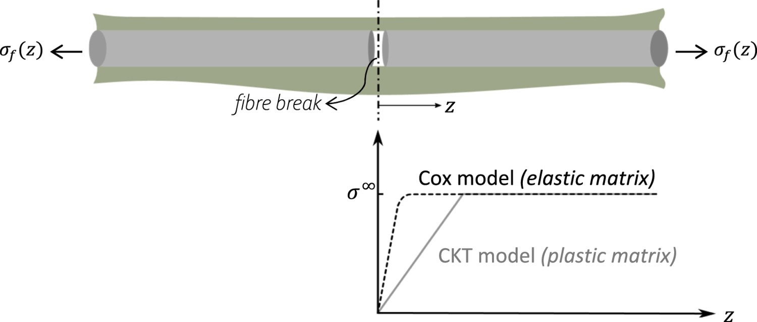
The shear-lag approach, developed by Cox (1952) [108], assumes that the matrix in a polymer composite is exceedingly compliant compared to the fibre. The matrix, therefore, does not contribute significantly to the tensile stiffness of the composite. Accordingly, the acting longitudinal loads in the matrix can be neglected, simplifying the calculation of fibre stresses. The matrix is exclusively responsible for transferring shear loads occurring at the fibre ends of a discontinuous fibre or a fibre break site. These shear loads occur due to the mismatch in longitudinal strain between the fibre ends and the surrounding material. To generate an analytical formulation, a matrix volume around the fibre, whereupon the shear stresses act, is required. This volume commonly takes the form of an arbitrarily drawn cylinder with the radius 

Lacroix et al. [109] used a unimodal Weibull distribution for the fibre strength to predict the critical length in SFFTs. They compared the results for fully-elastic (perfect adhesion), partially-elastic and total-debonding 1D shear-lag-based models. The fully-elastic model predicts that the critical length decreases as the applied strain increases, while the total-debonding model considers it a material constant (assuming frictional sliding stress to be strain-independent). The more realistic partial-debonding model predicts lower values of critical length compared to the overestimated lengths by the CKT model, underlining the significance of considering both IFSS and frictional sliding in processing the SFFT data [109].
The Cox-based models, limited by the introduction of the effective matrix radius, Predicted stress recovery profiles by CKT and Cox models (adapted from [115]).


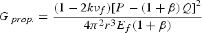
Following the initial shear-lag analysis, the extended SLMs include models with a matrix carrying tensile stress [116], elastoplastic matrix [117,118], debonded fibre–matrix interfaces [119,120] and matrix with linear damage evolution along with interfacial slipping [121]. The shear-lag analyses have also been supplemented with fibre-strength statistical models [120,122,123] to predict composite failure. The polymeric matrix properties can also affect the measured interfacial properties. Based on Cox's [108] prediction (see Table A1), the IFSS increases with increasing matrix shear modulus, 

Other stress-based models
The 2D analytical models (based on axisymmetric micromechanics analyses) for SFFT were premiered by Whitney and Drzal [127] and were later refined by the variational mechanics’ approach by assuming the axial stress to be independent of the radial direction either in both constituents [128] or merely in the fibre [129]. The axisymmetric model of Whitney and Drzal [127] (relevant equations given in Table A1) was competent at estimating all the stress components (also for transversely isotropic fibres) and reforming the shear stress distribution of the SLMs. The duo employed a stress function method that ensured a valid solution, but it had two drawbacks. First, their stress function was not based on one that minimises the complementary energy. However, this solution showed good agreement with experimental data for high aspect ratios of fibre length over 
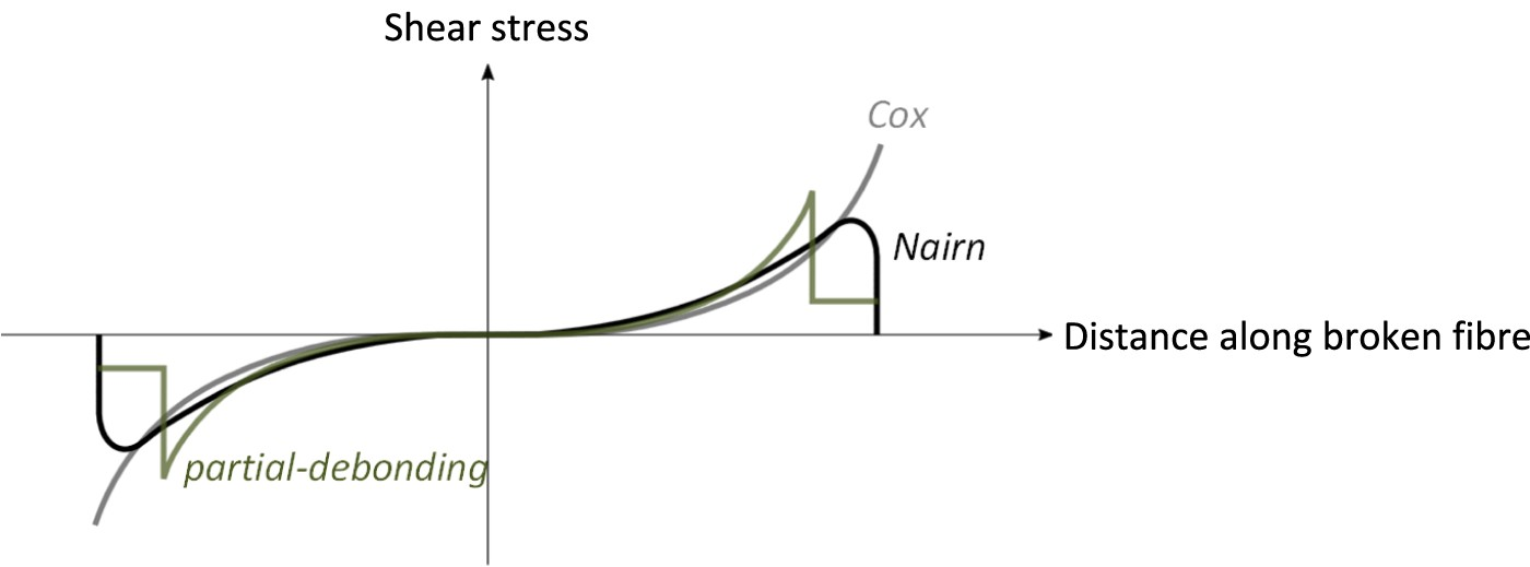
The location of the debond tip reveals itself as an inflection point in the fibre axial stress profile, with the debonded region having a linear stress build-up, while the rest displaying a Cox-type stress profile [35]. A key discrepancy between models is the shape of this transition region between the debonded and intact regions. Piggott (or similarly in [110]) claims that this shift is an unsmooth point of mathematical discontinuity, while Nath et al. [35] argue that the transition is smooth. This discrepancy emerges due to the linear elasticity assumption in Piggott's analysis, leading to stress singularities at the crack tip and a discontinuity in the stress recovery profile. Contrarily, the plastic zone at the crack tip in [35] creates a smooth transition in the fibre stress recovery profile. Figures 7 and 8, respectively, compare the axial stress recovery of the broken fibre and the interfacial shear stress profiles for the full-bonding and partial-debonding models.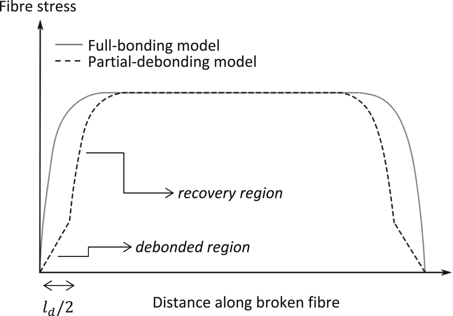
To conclude, Cox [108] and CKT [81,82] models offer analytical solutions to the interfacial stress transfer problem. Cox's SLM, presuming a linear elastic behaviour for both constituents, enables the determination of the fibre axial stress and shear stress between the fibre and matrix. This model is only viable at low applied strains before the inherent non-linear behaviour of epoxy resins at higher strains. The CKT model uses a perfectly-plastic matrix and determines the critical length by assuming a constant interfacial shear stress. Table A1 in the Appendix elaborates on the major stress-based analytical models.
Assuming the perfect interfacial bonding and disregarding the existence of matrix axial stress can lead to inaccuracies in predicting the load transfer mechanisms and overall mechanical behaviour of FRPs using SLMs. Various solutions and alternatives to traditional SLMs have been proposed to address this issue, such as FE models and improved analytical models. For instance, Nardone and Prewo [133] considered the load transferred from the matrix to the end faces of the fibre, which was overlooked in Cox's original SLM that assumed a continuous or significantly long fibre compared to its 
Energy-based approaches
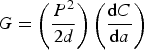
The CKT model is not always accurate in calculating the IFSS when saturation is not attained. This drove the development of alternative data reduction methods, such as energy-based approaches [98]. Interfacial debonding is a major energy absorber during composite damage and failure [137]. An energy-based approach (fracture mechanics) is an eligible alternative to the traditional stress-based methods (strength of materials) for interpreting the SFFTs. The energy-based method was instigated using approximate Bessel–Fourier [138] or shear-lag-based (Cox-based [139] or Nayfeh-based [140]) analyses. With IFFT (

In FRPs with relatively poor adhesion, the released energy during fibre breakage typically initiates a short interfacial debond at the vicinity of the break [141]. However, the debond remains arrested at a certain distance since the strain energy release rate (SERR) decreases as the debond grows. Owing to the larger Poisson's ratio and coefficient of thermal expansion (CTE) of the matrix compared to the fibre, the debond crack surfaces are continuously in contact. Thus the debond propagation is mode II-dominant [21,85,142] under tensile loading and below the curing temperature. Additional debond growth would require an increase in the applied strain [21]. Note that due to the brittle nature of the epoxy matrix, it is inclined to crack under tensile stress, which is the predominant mode of stress in mode I loading. The mentioned IFFT in the majority of the interface characterisation tests is more representative of a (near-) pure mode II cracking since the applied stress in mode II loading is parallel to the interface, which puts more stress on the interface itself rather than the matrix. However, in transverse cracking, both mode I and II components play a role.
Wagner et al. [143] use a 1D approach to determine the interfacial fracture energy caused by the initial debond. Their approach compares the energies before and after fibre and interface failure and considers the matrix contribution to the energy balance. The debonded region was assumed to be frictionless, and the residual stresses were neglected. However, the Boundary Element Method (BEM) [85] included the effect of these two key debond propagation suppressors. Using the solution of the BEM model (investigated for GF-epoxy), Graciani et al. [144] speculated that SERR evolves linearly with applied strain, 


It is peculiar that the two models identify widely different parameters despite using the same raw data, whereas both approaches incorporate Poisson's effects as well as frictional and residual stresses. In pursuit of a practical approach for more explicit identification of the interfacial parameters, Sørensen [147] developed a simple 1D SLM that determines the interfacial fracture energy and frictional sliding shear stress using the documented applied strain, debond length, and opening displacements of the fragment ends in the SFFTs. Using the potential energy approach of Budiansky et al. [148], Sørensen [147,149] considered friction and residual thermal stresses but dismissed the effect of matrix plasticity. Consequently, a more inclusive model that incorporates all relevant interfacial and material features is required to investigate the detailed stress transfer attributes of the constituents.
Numerical methods
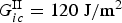
Overly simplified perfectly-bonded or fully-debonded models disregard realistic debonding and pull-out mechanisms. The majority of the existing analytical interface models, such as Cox's SLM, assume a well-bonded condition and no interfacial friction ( Cohesive zone model for mode II fracture with various softening laws (inspired by [162]).


Based on an axisymmetric single-fibre FEM [150], the limiting radius into the matrix beyond which no stress transfers is reported to be at least 20 times the fibre radius (

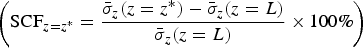
The SLM is widely employed for calculating the ineffective length (twice the length at which 90% of the broken fibre stress is recovered) and/or SCFs in FRPs. SCF is the relative increase of the cross-sectional average stress, 


A new interface model based on continuum damage mechanics was established to investigate interfacial debonding in CF- and GF-epoxy composites in 2D [169]. The discrete element method (DEM), developed initially to model movements within granular media [170], has been extended to laminated FRPs and interfacial debonding issues [171–173]. To better describe the post-failure frictional behaviour [173], 3D DEMs were conceived. Recently, a 3D DEM with an interfacial cohesive contact model was developed based on experimental SFFTs [174]. The novel 3D FEM of AhmadvashAghbash et al. [175,176] considers the significant interrelated phenomena during CF-epoxy debonding, including thermal residual stresses, frictional sliding, matrix crack and matrix plasticity, and does not pre-impose the debond length (see Figure 10). Their predicted stress recovery profiles were verified versus those obtained with Raman spectroscopy. Using this 3D FEM, a reliable simulation of a debonding single fibre can be tailored to multi-fibre models, whereas the improved accuracy of the stress concentration factor predictions enables generating authentic numerical fibre break models and optimising composites at fibre level for a preferential behaviour. 3D FE model of single-fibre debonding model: (a) reduced wedge model (due to symmetry) and assigned boundary conditions, (b) mesh refinement biased towards the interface and the debonding zone and (c) predicted stress recovery profile for the broken fibre throughout the applied strain of 2%. Note that the indicated half-debond length corresponds to the extent of the initial linear segment of the stress profile (reprinted from [175], with permission from Elsevier).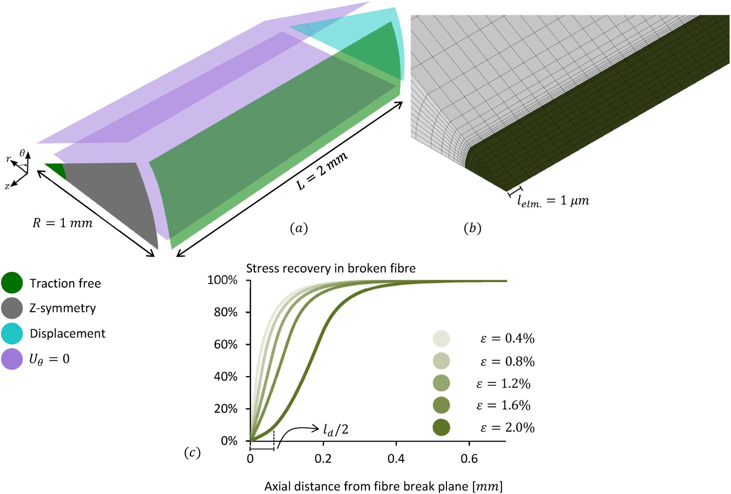
Experimental characterisation techniques
Laser Raman spectroscopy
A Raman spectrum can be acquired from materials that scatter light inelastically. Laser Raman spectroscopy (LRS or micro-Raman (MRS)) enables the evaluation of the stresses in CF-reinforced polymers (CFRPs) using the stress/strain dependence of certain vibrational modes of the fibres [39,177,178]. Although simplified, the following explanation helps to grasp the fundamental concepts of using LRS for conducting microstrain measurements (for further details regarding the basics of LRS and its utilisation for strain measurements, as well as the necessary instrumentation, the interested readers may refer to [179]):
Vibrational energy states exist between the electronic states of a molecule or crystal, and when a group of atoms vibrates, it causes instantaneous changes in the electron cloud and polarisability. This periodic change in the charge distribution interacts with an external electromagnetic field, leading to various light scattering phenomena, including infrared and Raman effects. If the incoming light frequency matches the frequency of a normal vibrational state in the material and results in a dipole moment alteration, the light is absorbed, and this is how infrared spectroscopy originates. When the incoming frequency does not match a normal vibrational frequency, the material can be excited to a virtual excited state and scatter light either elastically (Rayleigh scattering) or inelastically. Raman scattering is a type of inelastic scattering. The Raman effect occurs when the molecule or crystal drops from the excited state into a normal vibration mode with either higher or lower energy than its initial state and if there is a change in the molecule's polarisability. The scattered photon's energy equals the initial energy plus or minus the molecule's vibrational energy. Various types of reinforcing fibres, including graphite, aramid, rigid rod polymer fibres, silicon nitride and highly aligned organic fibres like polyethene, display a shift in their Raman peak when subjected to compressive or tensile strain [179]. These shifts in amorphous materials, such as CF, are mainly due to strain-induced lattice deformation, changes in the degree of disorder and interfacial debonding.
Galiotis et al. [180] were the first to adopt LRS to evaluate the strain dependence of Raman peaks in polydiacetylene fibres rather than crystals along with the Raman response of a crystalline urethane resin system [181]. Robinson et al. [178] and Galiotis et al. [177] subsequently analysed and evaluated the Raman spectrum response of various types of CFs under uniaxial stress. This was followed by a series of studies by Galiotis et al. [36,179,182–184] regarding fibres embedded in polymer resins and identifying interfacial stress transfer efficiency. A review [185] of the relevant work on FRPs was presented in the 1990s. Figure 11 displays a diagram depicting the standard LRS equipment along with strain profiles that have been fitted for both the broken and an adjacent fibre. LRS is capable of measuring the fibre stress with a spatial resolution in the order of 1 

LRS can yield a detailed understanding of the stress transfer micromechanics in SFFT. The obtained stress variation along the fibre assists in discerning between bonded and debonded interface regions and can be employed to validate fibre axial stress predictions by straightforward stress transfer models (CKT, SLM) or more elaborate ones which consider plasticity, friction and so forth. Hence, after acquiring raw experimental data via SFFT augmented with LRS or optically assisted SFFT, estimating the interfacial properties requires using a reliable model to predict the interfacial stress transfer.
Huang and Young [42] utilised both strain-induced Raman band shifts and stress birefringence patterns during SFFTs. Their experiments confirmed that for low strain levels (pre-debonding), the fibre strain distribution follows a Cox-type SLM. Recently, Zhu et al. [189] developed an analytical model for inverse identification of all three interfacial properties: IFSS, IFFT and Axial stress recovery profile along a T50-U fibre in an epoxy matrix at 


In addition to its quantitative precision in yielding fibre axial stress, another experimental advantage of the LRS approach is its application versatility. In tensile procedures for determining IFSS, as mentioned earlier, the strain-to-failure of the matrix should preferably be up to three times greater than that of the fibre to ease measurement [153]. However, for Raman-active fibres, the LRS can be employed for matrix/fibre strain-to-failure ratios much smaller than this [154], which is more indicative of engineering applications.
Photoelasticity
Polarised light can be used to monitor the in-situ fragmentation process. Since the epoxy resin is stress-birefringent, cross-polarisers enable the observation of the stress state near fibre breaks and the interface [38]. A schematic illustration of a typical fragmentation test setup is shown in Figure 13. Once the fibre breaks, the specimen exhibits birefringence colours (or photoelastic patterns) surrounding the broken fibre ends due to the developed shear stresses at the interface as a result of stress transfer from the matrix to the fibre. The tensile stress drops to zero in the break gap between the fragments, creating a zone with no birefringence. This phenomenon offers a valuable tool to observe shear strain patterns and the fracture of opaque CFs. The birefringence usually exhibits symmetric features around the given fibre break and becomes more prolonged and flatter for higher load levels (see Figure 14b). Upon saturation, the birefringence pattern ends almost touch each other, indicating that shear stress transfer takes place over the whole fragment length and further fibre breakage is then unlikely [38]. Schematic feature of the fragmentation test apparatus (adapted from [86]). The recorder displays the applied load level. Using polarisers and a camera, events such as fibre breaks, debonding, matrix cracking and the resulting photoelasticity (or birefringence) are observable. The schematics of photoelastic birefringence patterns indicating the shear stress originated from an E-glass fibre break inside an epoxy matrix: (a) without interfacial debonding, (b) with debonding and (c) unloaded state with vanished larger birefringence (redrawn from [86]).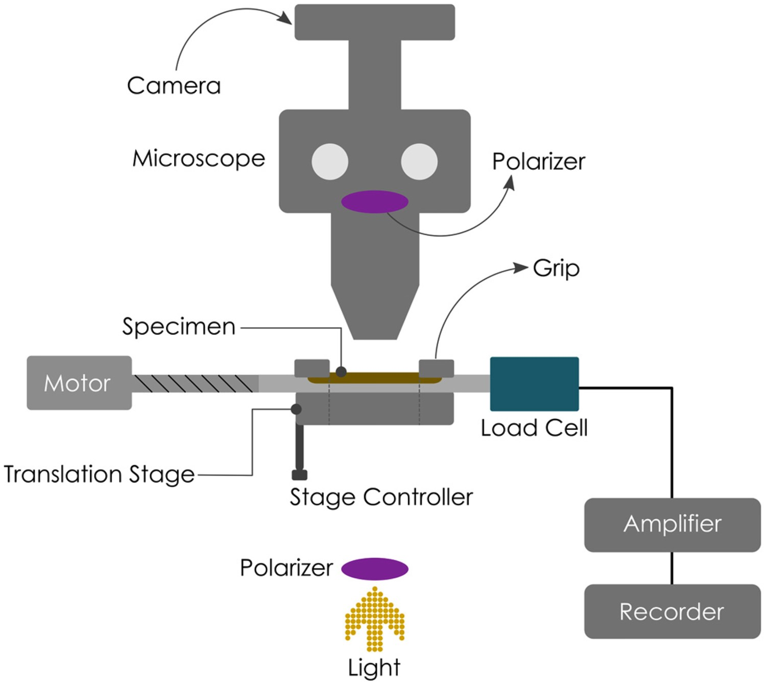
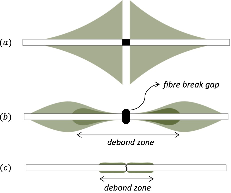
Reportedly, as-received (sized) CFs display a highly concentrated birefringent pattern within the adjacent matrix [62], indicating strong adhesion. However, unsized CFs exhibit noticeable break gaps and long debonded interfaces, with some debond zones even connecting to form ‘chain-like’ breaks. Epoxy systems exhibit extensive birefringence, which persists even after unloading the specimen (see Figure 14c). However, in polyester matrix systems, the birefringence is less prominent and promptly disappears once the specimen is unloaded [38].
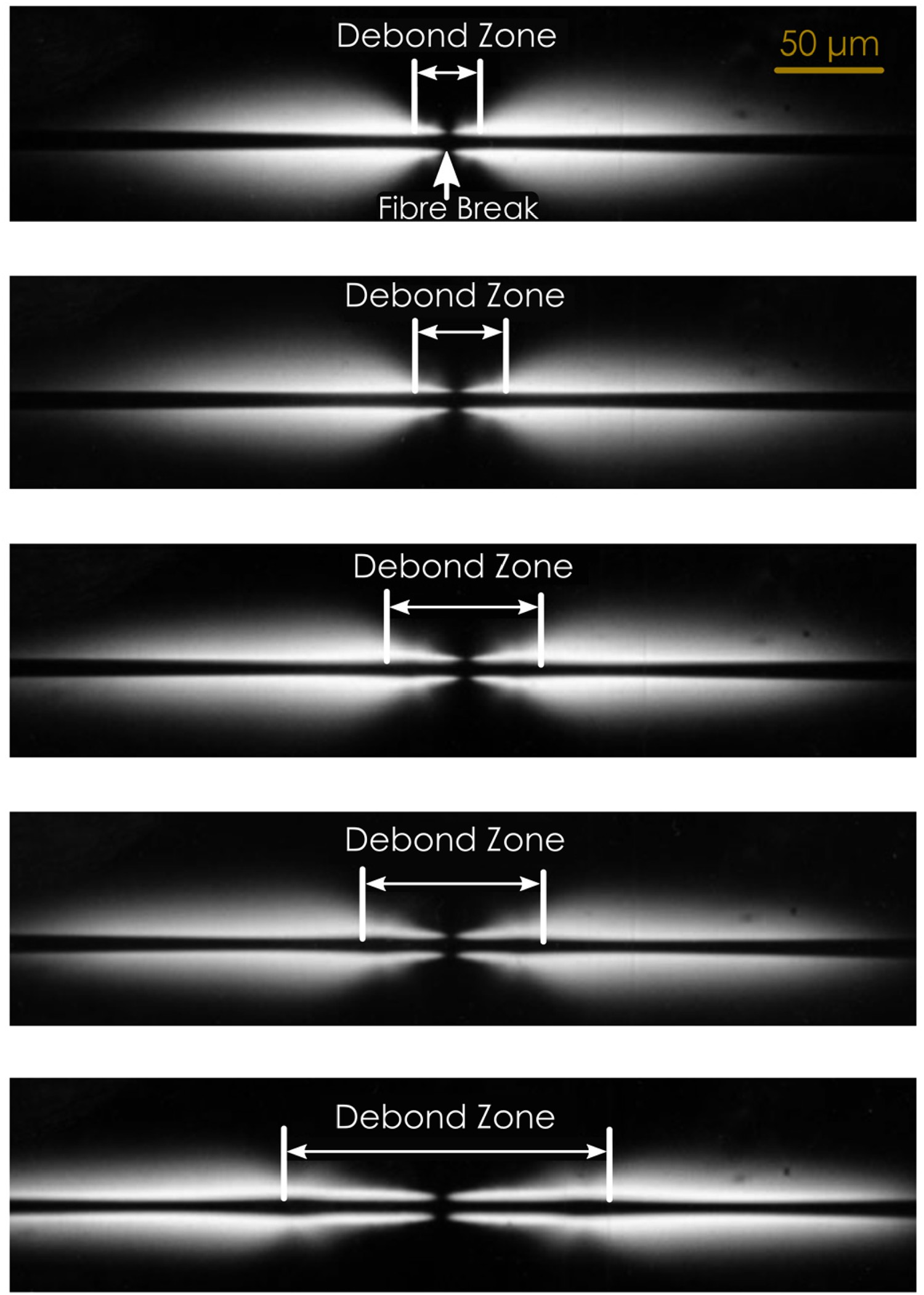
The birefringence patterns were employed to determine the debond length at each fibre break in epoxy resins in [86]. Figure 14 compares the two expected birefringence patterns for fibre breaks with and without debonding. Based on Kim and Nairn's [86] observations, the birefringence around the fibre break includes two distinct colours, representing the inner and outer zones (see Figure 14b). Upon unloading, the outer birefringence disappears, while the inner band remains visible (albeit contracted). The authors assumed that, throughout loading, the debond zone length was therefore equal to the length of the inner zone at the interface, as indicated in Figure 14(b). Commonly, half of the distance between the two brightest light spots observed in the photoelastic birefringence is regarded as the ‘experimentally measured Debond propagation for AS4 CF-epoxy as a function of applied strain (adapted from [86]).
Feih et al. [38] suggested an alternative definition for the debond zone extent by comparing the birefringence and white light images. The 
Multi-fibre fragmentation test (MFFT)
Conducting experimental investigations on stress concentrations in neighbouring fibres resulting from fibre fracture (and accompanying matrix failure) necessitates using model composites consisting of multiple fibres arranged in a precisely defined geometry and embedded within a matrix. Of specific significance is the requirement that the distance between adjacent fibres is limited to a few fibre diameters or less. This strict proximity criterion ensures the accurate examination and analysis of stress distribution and the intricate interplay between fibres within the composite structure. Except for the layout of testing frames and equipment, which is adjusted to ensure constant inter-fibre spacings, the multi-fibre fragmentation test (MFFT) closely mimics SFFT.
The interfibre spacing directly influences the effective stiffness experienced locally by fibres and thus impacts fragmentation length. An interfibre distance of 4 


In addition to enabling the in-situ strain measurements at the fibre level in single-fibre model composites, LRS is a valuable method for determining SCFs and also investigating the effect of the SCF on the subsequent failure process in multi-fibre model composites. The SCF and ineffective length have been measured experimentally using LRS [192–194] and are often calculated using SLMs. For instance, for 2D Kevlar multi-fibre micro-composites, the strain along the fibres was mapped, via LRS, at different load levels, and specimens with various inter-fibre spacings were utilised to investigate the effect of fibre content. The obtained experimental SCFs were compared with values predicted by different theoretical models, and in general, they aligned with the literature models that considered inter-fibre distance and matrix effects [192]. Similarly, CF-epoxy micro-composites with an inter-fibre spacing ranging from 0.8 to 19 


To obtain the maximum SCF from the experimental data, the strain profiles of the SCF in the fibres adjacent to a broken fibre, for instance, might be fitted to a Gaussian distribution function and the IFSS (using equation (34)). A Piggott-type stress transfer model [195], consisting of two linear stress build-up regions (CKT), was found to fit the experimental strain profiles better [187]. The suggestion made by the authors [187] is to enhance the existing theories by considering the local yielding of the interface in the area surrounding the broken fibre, as indicated by the strain profiles. A preliminary FE study that included this local yielding showed encouraging outcomes [187]. Concerning the effect of the inter-fibre spacing on the interfacial shear stress at the fibre adjacent to a break, an increase in the inter-fibre spacing led to a reduction in the interfacial shear stress [187].
Grubb et al. [196] suggested that SLMs, designed to model the behaviour of single-fibre fragmentation along the fibre axis, were inherently incompetent in modelling stress transfer between fibres. Nairn's SLM [111] offers the advantage of relying heavily on parameters such as 


Typically, the difficulty associated with MFFTs has been embedding small, brittle fibres at uniform inter-fibre intervals within a matrix [6]. Wagner and Steenbakkers [197] used a fibre spacing pin-array system, and fibres were placed between pin arrays, which were then rotated to deliver precise and reproducible interfibre distances in the eventual specimen. This approach performed well for Kevlar and other polymer fibres, but CFs and GFs broke too easily under rotation. Jones and DiBenedetto [198] employed rotating brass combs with 101 µm spacings. The interfibre spacing was controlled by adjusting the rotation angle on the device before depositing the aligned dry fibres in a silicone mould to cure. Li et al. [190] introduced another fibre-spacing tool that uses spacers to maintain fixed and settled fibre spacings. The MFFT specimens in [199] were prepared using the rotation device concept developed by Wagner and Steenbakkers [197] with modifications [200] made to achieve uniform interfibre spacings of about 1 µm. While MFFT test equipment has achieved increasingly more precise control over fibre uniaxial testing, fibre tension handling during fibre embedding is arduous due to the absence of an effective in-situ fibre local tension measurement. Additionally, the embedment process is typically manual, which introduces variability in initial fibre tension and potential undetected crazes on fibre surfaces that might trigger premature failure. Moreover, the literature lacks comprehensive consideration of the stress relaxation state of individual fibres within an array, highlighting the necessity for in-situ tension measurement during the embedment process. However, advancements in micro-actuators, sensors, and programming offer promising opportunities to overcome these challenges [6].
Conclusion
An SFFT moderately replicates the stress transfer characteristics in real FRPs and allows a large statistical interface sampling. Additionally, the critical length is sensitive to and reflects the changes in the fibre–matrix adhesion level, which is vital for a decent interface characterisation method. Fracture mechanics-based data reduction methods have been established which do not require fragmentation saturation. However, a highly complex/non-uniform stress state at the interface due to interfacial shear stress concentration near the fragment ends complicates the data analysis. Additionally, nearby fractures and fibre pre-tension integrate more difficulty into the analysis. The majority of the existing data reduction models ignore at least one of the key features of the SFFT. None of the developed approaches for SFFT has yet achieved adequate credibility to form the basis of a universal standard for the measurement of IFSS that could later be used to estimate the ILSS of a laminate [6]. An optimal data reduction method considers all the major interrelated phenomena during fibre–matrix debonding, including thermal residual stresses, frictional sliding and matrix plasticity, and avoids a pre-imposed debond length. Although it is possible to design a fragmentation test for a high 
The SFFT is severely limited by the elastic mismatch requirements between the fibre and the matrix. The test evaluations are consistent and reliable only if the fibre failure strain is several times lower than the matrix failure strain. The test is cumbersome to perform, and the specimen quality and success of SFFTs largely depend on the skill and experience of the operator. The process of isolating single fibres requires a high level of precision, and any errors can compromise the accuracy of the results. However, with careful preparation and attention to detail, SFFT can provide valuable insights into the mechanical properties of the interface. The key factors for the prevalence of the SFFT are the less intricate test setup and its applicability to brittle fibre systems and more frequent (relative to the other three main methods) attempts to ameliorate the data reduction methods. The SFFT is more suitable for CFRPs due to the small diameter and brittleness of CFs [42]. The SFFT, the only test involving fibre breakage while assessing the interfacial properties, is restricted to transparent or highly-translucent matrices with high failure strain. However, acoustic emission can be used to determine the length distribution of the fibre fragments, even for specimens with opaque polymer matrices and fibrillar fibre breaks [90]. The majority of the in-situ measurements of the fibre strain and debond length in SFFTs is acquired either by optical microscopy, photoelastic birefringence patterns (using polarisation filters) or LRS. The key advantage of LRS-derived axial fibre strain data is that 
Note that the direction (tension vs compression) or type of applied loading (static vs fatigue) may affect IFSS. A comparative assessment of stress transfer efficiency in tension and compression for a CF embedded in epoxy revealed that the rate of stress transfer from a fibre break was extremely high in compression, resulting in a short ineffective transfer length compared to tension. By further loading of the system, stress was transferred in the fibre not only by interfacial shear but also by fibre–fibre contact at the compressive failure location [201]. To observe the debond growth with increasing cycles, a single-fibre specimen containing a fragmented fibre can be subjected to axial fatigue loading. Previous fatigue tests on model composites with only 2–5 fibres have been conducted, such as in reference [202]. When a simulation tool is available for debonding process, combining experimental and simulation approaches can help identify the fatigue law and its parameters for the interface being studied. This information can then be used to analyse the fatigue of UD FRPs. The approach in [203] assumes that the propagation of an individual interfacial debond follows the Paris law. This law describes the growth rate of the debond as a power-law function of the difference between strain energy release rates at the highest and lowest load levels during cyclic loading. Moreover, approaches such as analytical, FEM and virtual crack closure techniques have been employed to analyse the debond growth in tension-tension fatigue using Paris law [21,142].
Additionally, the dependence on the load direction and specimen size is a distinct feature of thermosets matrices compared to thermoplastics. The stress–strain behaviour of macro-scale bulk epoxy resin specimens exhibits an over-reliance on the loading direction [204,205]. Performing tensile tests typically leads to a brittle behaviour [206] and, contrarily, specimens under uniaxial compression exhibit notable non-linearity and plasticity on both the micro- and macro-scales. The micro-scale shear behaviour, as the most relevant description of the matrix in SLMs, displays a similar stress–strain diagram as obtained by macroscopic compressive tests. However, there is currently no agreement on the best practice to measure the relevant epoxy constitutive properties for use in micro-scale composite models and, therefore, also on the correct constitutive model. Conceivably, a first-order approximation can be achieved by simulating the constitutive behaviour based on compressive stress–strain data through the use of a yield criterion [207,208].
Table A2 highlights the scatter in the reported interfacial properties measured with SFFT for CF or GF (separated by a horizontal dashed line) embedded in thermosetting or thermoplastic (TP) matrices. The immense existent ranges for the reported interfacial properties have received various rationalisations. High radial compression stresses can give rise to overestimated IFSSs (especially in TP matrices, related to the higher processing temperatures). Reportedly [209], the IFSS never exceeds the shear yield strength of the matrix. However, a widely used explanation for inflated IFSSs is that the polymer layer formed with a finite thickness around the fibre surface exhibits substantially different properties from those of the bulk matrix, which was criticised in [210]. The large 


Reportedly, in the case of intermediate-modulus (IMD) FRPs, the matrix tends to yield first rather than debonding along the interface, whereas in high-modulus (HM) FRPs, debonding may occur first. However, when the CKT model is adopted for IFSS calculation, its value is approximately half of the Tresca matrix yield stress. If the LRS-derived IFSS is considered more accurate, a clear disparity arises between credible experimental data for IFSS and the calculations of a classical theoretical model, with the LRS-measured IFFS tending to be twice that of the CKT IFSS [213]. The decrease in IFSS with increasing 


Single-fibre pull-out test
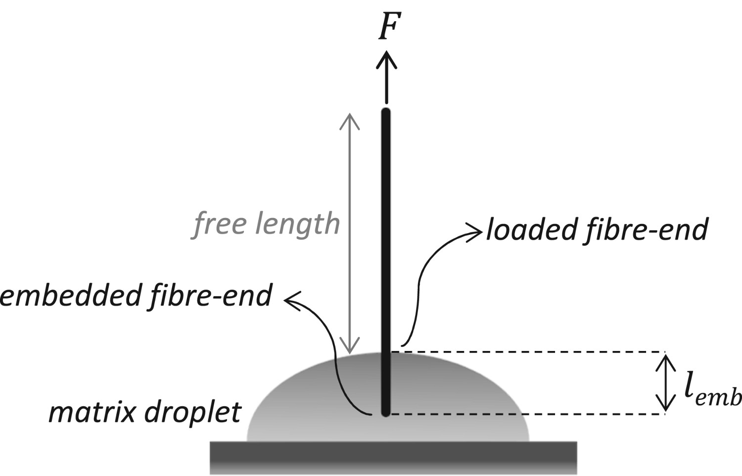
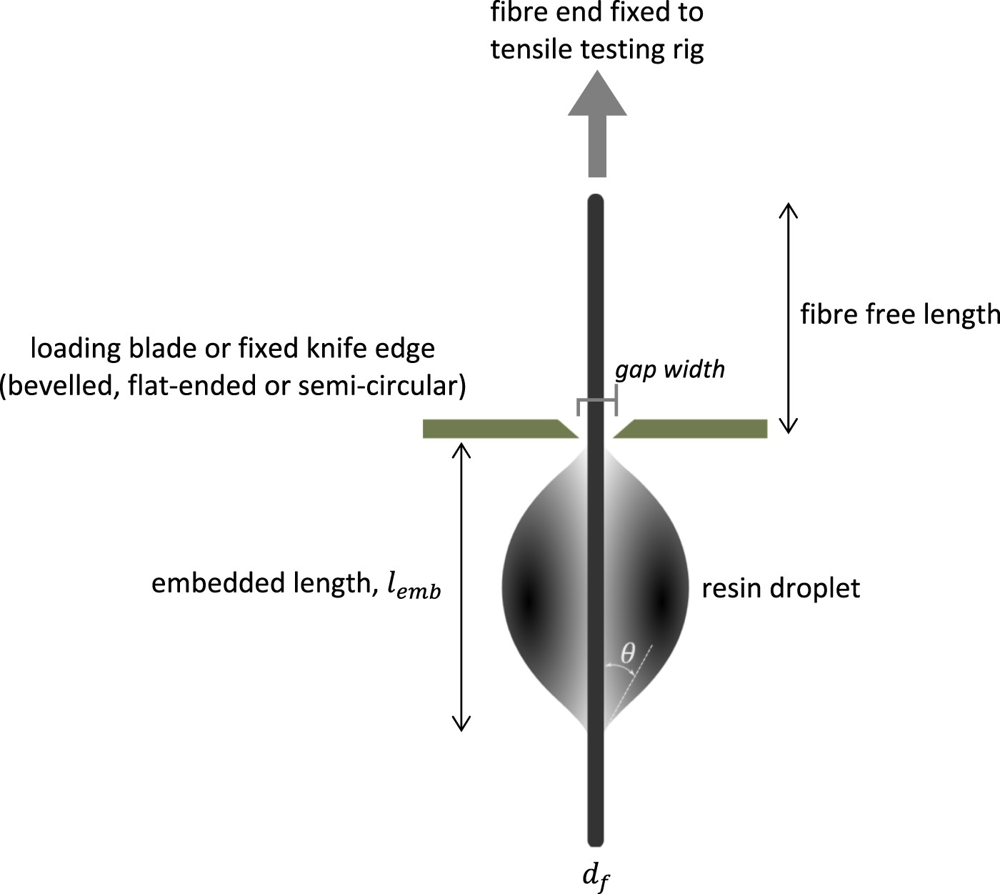
The single-fibre pull-out tests consist of performing a tensile test on an individual fibre partially embedded in resin and measuring the force needed to extract the fibre from the matrix (see Figure 16). This test was initially developed by Shiriajeva and Andreevskaya [214], and later modified by Favre and Perrin [215], Piggott et al. [211] and Hampe (1988) [216,217]. These modifications include adapted resin block formation for CFs, embedding a controlled, short fibre length and using a device for the stiffness-optimised pull-out test, respectively. This test is governed by the interfacial friction coefficient, interfacial pressure (caused by curing/cooling), work of interfacial fracture, fibre embedded and free length [218]. The pull-out test is challenging to perform but competent at providing the most comprehensive data since, under proper conditions, it allows measurement of IFFT, friction coefficient and shrinkage pressure [219]. The common impediments include the handling of delicate specimens and the difficulty of observing the failure events instrumentally or visually with sufficient details [220]. This test (Figure 16) requires only a small amount of material and can be used with both brittle and ductile matrices [221]. The analysis and interpretation of the experimental data is an elaborate task considering the various theoretical models developed for this test.
One of the primitive descriptions of the single-fibre pull-out test was given by Kelly in 1970 [222], elaborating on initial debonding, debond propagation, completion and fibre pull-out. Takaku and Arridge [223] clarified the dependence of the debonding and the pull-out stress on the embedded length ( Schematics of a single-fibre pull-out test, illustrating the fibre intersection on the surface of the matrix (loaded fibre-end), and its buried end (embedded fibre-end).

Load–displacement response
The pull-out load–displacement curve generally contains the typical linear elastic, crack propagation and fibre pull-out zones. According to Piggott [224], the evident regions can be distinguished in each plot as: a linear increase in force with displacement; a shift in slope or a convexly curved region, indicating matrix yielding at the interface; an abrupt decrease in force due to interfacial failure and force re-establishment and a knobbly region with decreasing force.
For the reported experiments in [224], all systems have a region (i) to a greater or lesser extent, and Kevlar-epoxy and GF and CF in thermoplastics have a distinct curved region (region ii). GF-polyester and GF-epoxy [212] have no region ii, whereas CF-epoxy does. Reportedly, all systems display a sudden decrease in force and only the systems with shorter Schematic illustrations of three typical force–displacement curves for the single-fibre pull-out test of brittle fibre-resin systems: (a) for strong interfaces or weak interfaces with small 

It is customary, although not necessarily correct, to associate Theoretical relationship between the embedded length and the load required to debond (redrawn from [220], with permission from Elsevier).


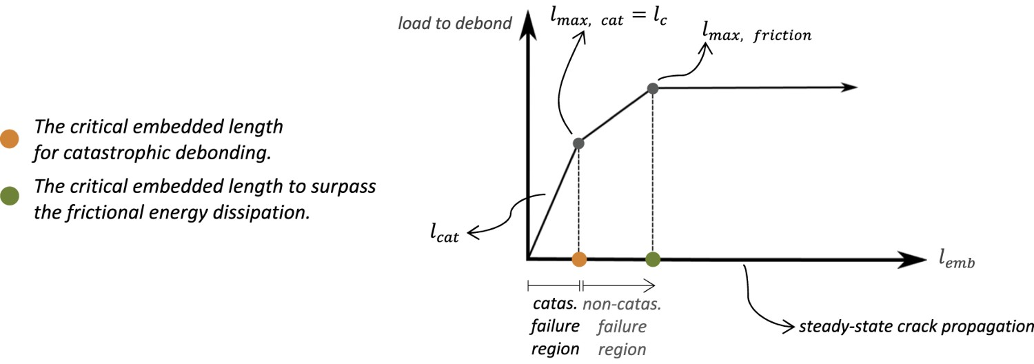
The most basic model for the fibre pull-out process is the constant interfacial shear stress (linear 

The apparent maximum debonding force increases with 


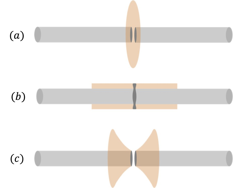
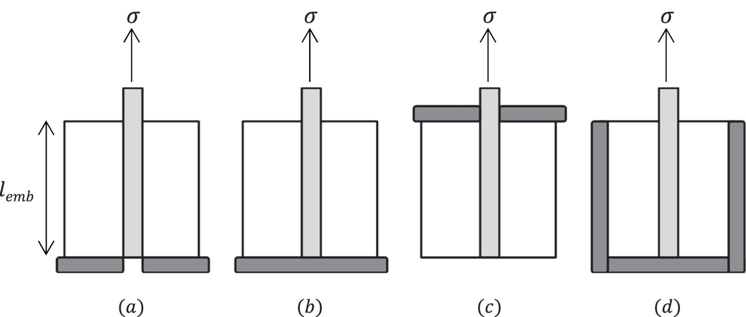
Specimen design and test setup
A carefully designed experiment, in addition to IFFT, can yield data on the frictional region of the pull-out curve. Regarding the test configuration, different boundary conditions would provoke different stress states in the constituents [229]. Figure 19 demonstrates the schematics of various fibre pull-out configurations in analytical models. Commercial devices have been developed to (partially) automate the pull-out procedure [230]. For the pull-out process, there are advantages to using a stiff loading system (including fibre grips, drivetrain and so on) to achieve controlled and stabilised debond propagation [218]. To ensure a highly stiff test setup, the Federal Institute for Materials Research and Testing (BAM), in addition to piezo force sensors, has utilised piezo translators for precise displacement generation [217]. The components were mounted on a stiff steel frame and reported to yield stable crack propagation during the pull-out test. Often the most compliant part of the test setup is the fibre itself since a significant length of fibre (the free length, see Figure 16) connects the embedded part of the fibre and the part in the grips. This free length mainly reduces the reliability of the post-debonding frictional data [218]. Even moderately short free lengths (a few Schematics of various fibre pull-out configurations in developed analytical models: (a) fixed matrix bottom, (b) fixed fibre and matrix bottom, (c) restrained matrix top [229] and (d) bounded bottom and sides, after Piggott [211] (subfigures (a–c) are redrawn from [229], with permission from Elsevier).


In a pull-out test, it is crucial that interfacial debonding occurs ahead of the fibre break. Since the interfacial debond force is directly related to the 


The in-situ observations could include LRS [235,236] and photoelasticity (isochromatic fringe patterns) [232]. The single-fibre pull-out test was analysed for Kevlar-cold-cured epoxy using both conventional pull-out and LRS-coupled tests in [225,237]. At low strains, the behaviour follows the elastic shear-lag analysis, but as the fibre strain increases, interfacial debonding occurs. Reportedly, the conventional pull-out test only produces an apparent IFSS value, and employing a partial-debonding model allows using the interfacial parameters obtained from Raman spectroscopy to predict the data from the conventional pull-out test [225].
Data reduction schemes
Stress-based methods
The stress-based models, being plainer than the energy-based approaches, target estimating the interfacial stress profile in accordance with the applied load. It is generally agreed upon that the strength approach, neglecting friction, can be applied to a totally unstable debonding process with short 


Note that 
Lawrence et al. [243] introduced the partial interfacial debonding concept with a debond initiating at the loaded fibre-end and propagating towards the embedded fibre end, while the effect of frictional shear stress was included throughout the debonding process. The authors recalculated the shear stress distribution to an expression analogous to that given by Greszczuk [240] but with a different elastic constant [239]. The Lawrence model predicts the debond stress satisfactorily for short 

The analytical model of Zhang et al. [244] (developed for continuous fibre-reinforced cementitious composites) divides the pull-out curve into three segments: perfect bonding, debonding and pure friction. The matrix was considered as a rigid non-deformable body, and the constituents were isotropic and linearly elastic. Their proposed shear stress profile is reminiscent of a CZM with a bilinear traction-separation law coupled with a frictional sliding after debond completion. Sørensen and Lilholt [24] developed a relatively simple 1D analytical SLM that incorporates the residual stresses but neglects the Poisson effects. Hsueh [245,246] included the effects of interfacial debonding, residual radial and axial stresses and fibre sizing and determined the axial strains of the constituents only by the axial stresses and disregarded the effect of Poisson contraction [247]. Regarding the micromechanics of elastic stress transfer, a two-cylinder model for the single-fibre pull-out test and a three-cylinder model for the multi-fibre pull-out test were compared in [248]. This comparison revealed the importance of neighbouring fibres (local fibre volume fraction). Concisely, none of the current and prevalent stress-based models capture all relevant features within interfacial failure in FRPs.
Energy-based methods
The strong heterogeneous interfacial stress distribution, exhibiting stress singularities, suggests that a stress-based evaluation of the test data is not entirely appropriate [249]. Based on Griffith's fracture criterion [250], an interfacial crack propagates once SERR (


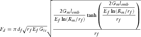
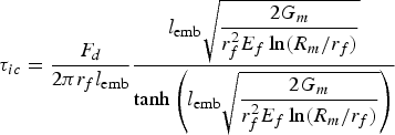
The geometry considered by Penn and Chou [254] is more comparable to that of the microbond test (in the absence of the blades, see Figure 20). By assuming an initial interfacial crack size of length Schematic of the microbond test set-up (redrawn from [255]).

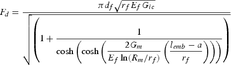


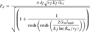
Piggott's expression for the debond force as a function of the interfacial toughness and the 
The majority of energy methods assume a stable interfacial crack propagation with a constant value of the IFFT. Therefore, these approaches cannot be applied in the case of short 
Owing to its simplified equations and methodology in assessing the interface parameters based on experimental data, the Gao–Mai–Cotterell model is extensively exploited by other researchers. This model has been adapted to incorporate the effects of loading mode [229], fibre anisotropy [257], interfacial roughness [258] and fibre volume fraction [259]. Hutchinson et al. solution [84], based on the Lamé solution and considering the debond as a mode II fracture, was limited to systems featuring residual compressive stresses.
As mentioned earlier, debonding can be viewed as either complete or partial. In the case of partial debonding, the friction parameters must be considered in the pull-out analysis [239]. Accordingly, the partial debond stress was represented as a function of the debond length in [260], based on fracture mechanics. However, the expression for their debond stress was intricate, and the same interfacial parameters were obtained using a simpler model in [83], overshadowing its practicality [239].
The debonding stability is regulated by the elastic constants, the relative volume of fibre and matrix, the nature of the interfacial bonding and the 
The shear strength-based approach of Hsueh [262] and the energy-based approach of Gao et al. [83] were compared with experimental results in [261]. In Gao et al. [83], a pre-debonded interface is modelled as a stable interfacial crack propagating with a constant interfacial fracture toughness under plane strain conditions. Both models, considering an SLM, contain the effects of friction at the debonded region and Poisson contraction by assuming that the debond propagates from the loaded fibre end (no two-way debonding) [261]. For epoxy matrix composites, Gao et al. model [83] predicted the trend of maximum debond stress quite well for long 


The model of Gao et al. [83] was later applied by Kim et al. [263] to determine the IFFT, friction coefficient and residual fibre clamping stress. A stochastic approach (Ising model combined with Monte Carlo simulation) was applicable to partial debonding, fibre breakage and matrix failure [238] in the course of a single-fibre pull-out. The energy-based models of the pull-out process can also be solved with the aid of FEM [249]. For instance, Atkinson et al. [264] calculated the energy release rate in a pull-out test using FEM.
Numerical methods
One of the earliest FEMs for the fibre pull-out test, based on the energy method, was developed by Beckert et al. [265]. They incorporated the thermal residual stresses, specimen geometrical features and a basic model for interfacial friction. In a perfectly bonded system, a parametric study with different fibre/matrix stiffness ratios and irregular fibre cross-sections was carried out in [266]. The effect of 
The CZM bridges the gap between the stress- and energy-based approaches. Tsai et al. [267] used a CZM-friction interface model to simulate copper fibre-epoxy pull-out. In their axisymmetric FEM [268], CZM was used to explore the effect of various interfacial parameters in a single CF pull-out test. The debonding force was found to have a linear relationship with the IFSS and fibre geometric parameters (


Machine learning techniques have the potential to significantly enhance the accuracy, efficiency and automation of numerical models for interface characterisation methods. It is advisable to explore novel machine learning algorithms and techniques, develop hybrid models that integrate machine learning with conventional numerical methods, and examine the potential of machine learning in multi-scale modelling. For instance, the FEM with cohesive damage model and frictional contact for the interface was combined with Artificial Neural Network (ANN) to study the load-displacement behaviour during fibre pull-out in fibre-reinforced ceramic composites in [271]. The ANN, trained and tested using an analytical model and an FEM, can accurately predict load-displacement behaviour. By utilising a larger dataset of experimental results, the ANN can be thoroughly trained to capture the elaborate details derived from experimental observations, which otherwise are challenging to investigate through analytical models [271].
Frictional behaviour
Friction is described by two independent parameters: the friction coefficient (


Contrarily to the conventional Coulomb friction (

Conclusion
The pull-out test can directly estimate the IFSS and provide information on friction coefficients and shrinkage pressures. Despite being an excellent choice for novel fibre–matrix configurations (e.g. fibres with interfacial topographical anchors), this method is challenging for brittle fibre systems. Apart from demanding specimen preparation and handling, this method is governed by critical embedded fibre length and is limited to maximum embedded lengths of tens of micrometres for certain systems (lower bound due to meniscus formation and upper bound constrained by fibre strength [100]). The existence of high shear stress concentration near the loaded fibre-end and lower shear stress concentration at the embedded fibre-end complicates the interfacial stress state. Another challenge associated with single fibre pull-out testing in FRPs, apart from a prerequisite thorough interpretation of the load-displacement trace, is that the interpretation varies between laboratories [220]. These interpretations have primarily centred around the maximum point in the load-extension diagram. If this maximum results from a catastrophic interfacial failure, the 

The stress distribution of an appropriate test configuration must be similar to that in a bulk composite. For composites with brittle fibres and ductile matrices, the favoured candidate is the SFFT. Contrarily, for composites with brittle matrices, inducing failure via multiple transverse cracks, the pull-out test seems more appropriate [279]. Systems with strong interfaces entail very small critical 


Table A3 summarises the interfacial properties from pull-out tests reported in the literature. The IFSSs estimated from shorter 
Microbond test
The microbond test (or MB, MBT, microdrop, microdroplet, micro-debond, microbond pull-out or single-fibre-microbond-pull-out), as a revision to the conventional pull-out test, was incepted by Miller et al. [280]. Since, for an individual test, only a minuscule proportion (droplet, microdrop) of the resin is deposited on the fibre, this method is referred to as the microbond technique. In the early years of interfacial testing, the weaker reinforcing fibres were thicker and favoured by the pull-out test. However, contemporary and commercially available thin fibres demanded the conceiving of new methods, such as the microbond test.
The microbond test enables interfacial characterisation of relatively thin fibres (
The experimental procedure follows the curing of a resin droplet onto the surface of a single fibre (see Figure 20) and then applying a constant velocity to the loading knife (also called a blade, razor blade, micro-vise, micro-vise plate, miniature grip, shearing plate or simply plate). This motion exerts a shearing force on the droplet as it moves downwards and pulls the fibre out. Alternatively, the knife can be stationary while the fibre is pulled upwards at a constant velocity. Further discussion will be held on the impact of the various parameters depicted in Figure 20.
The droplet must form symmetrically, concentrically and ellipsoidally around the fibre to ensure concurrent contact with the knives and a uniform interfacial loading. If the contact angle is relatively low and the ratio of the droplet volume over 


Contact angle
The surface energy of solids (and the surface tension of liquids), serving as a direct indication of intermolecular forces, encompasses Lifshitz–van der Waals (dispersive), basic and acidic components. By considering these components, one can assess the physical adhesion between two dissimilar materials and indirectly infer their compatibility [283,284]. The fibre surface energy, as an essential physical parameter to assess surface activity, and one of the key parameters in determining the final interfacial properties, is difficult to be directly measured due to the cylindrical shape and the small diameter of the fibre. Typically, the fibre surface energy, or wettability of the matrix on the fibre surface, is determined by the contact angle (
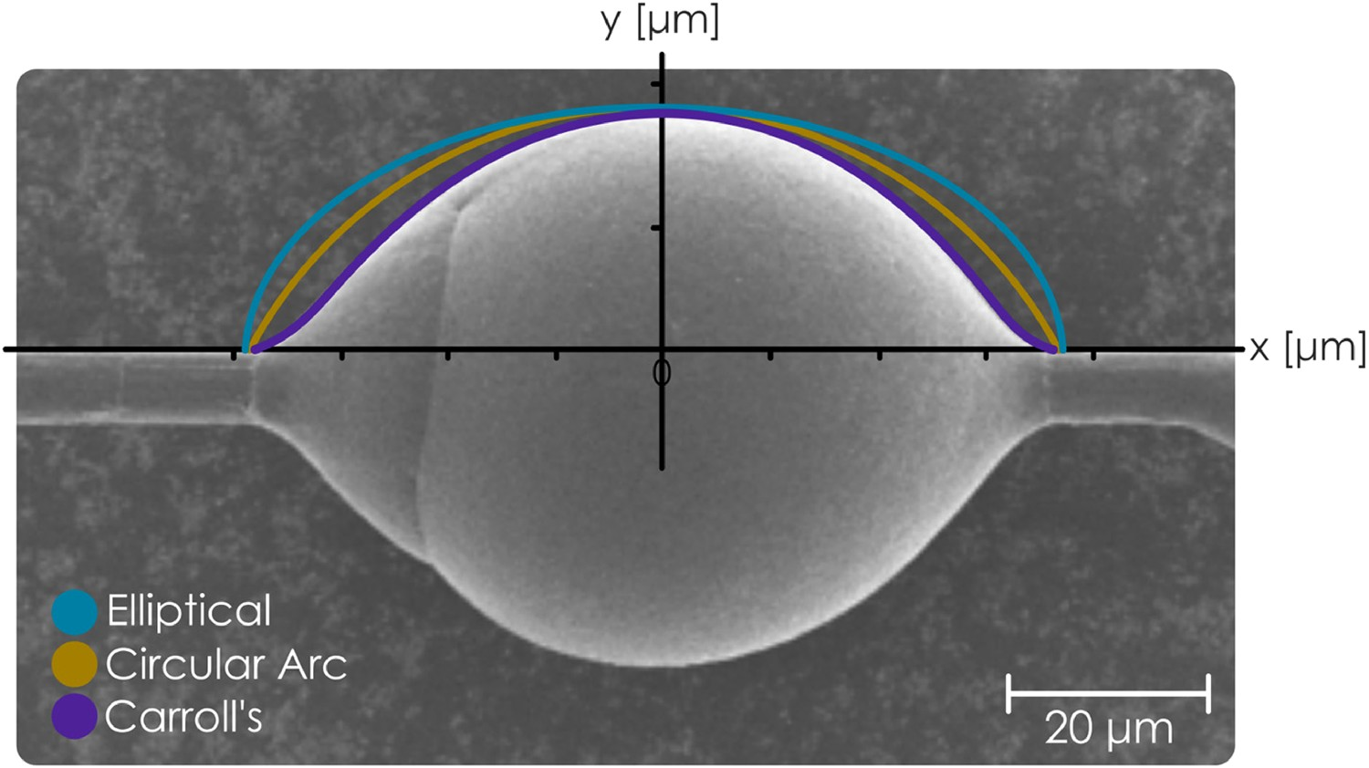
Carroll [285] and Yamaki and Katayama [286], concurrently and independently, developed analytical models to determine 


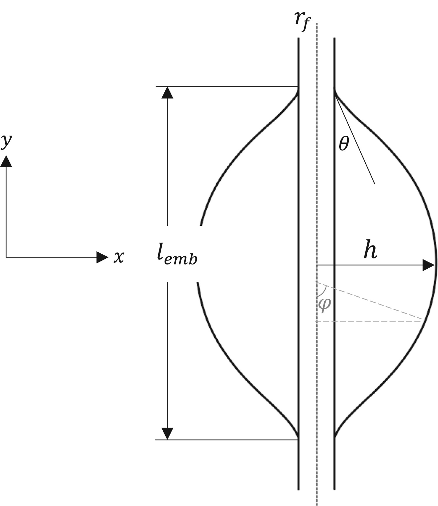
To provide a visual representation, a comparison of an elliptical fit, circular arc fit and Carroll's fit to an SEM image of a thermoplastic droplet on a sized CF is presented in Figure 21. Carroll's equation assumes the preservation of the unduloid shape of the droplet within both its initial liquid form and after its consolidation, considering negligible gravitational effect. The droplet profile (see Figure 22) on a cylindrical fibre is determined by the following two equations [285,291]: Schematics of the droplet profile in a microbond test and the parameters for determination of the contact angle (redrawn from [285], with permission from Elsevier).

The optical measurement of 


The ‘debonding cone’ phenomenon commonly occurs for a brittle matrix system (such as epoxy) when 
Specimen design and test setup
The absence of a standardised procedure for the microbond test has generated discrepancies in experimental setups among research groups, with universal testing machines equipped with low-capacity load cells being the mainstream approach. However, reliable measurement of the interfacial properties requires appropriately scaled exclusive equipment, as in [294]. In addition to having a highly stiff testing device, enabling a precise displacement measurement due to stabilised crack propagation, a shorter fibre free length, 


Regarding the effect of the loading device types, [299] reports higher average IFSS values (and lower scatter) utilising a pin-holed steel film over microvise tips in quasi-disk type microbond specimens. Mendels et al. [292] reported that the numerically calculated IFSS is independent of the loading point location if it is positioned in between the inflection point of the droplet profile and the endpoint of the droplet. The inevitable discrepancies concerning the droplet configurations, as a consequence of 

Concerning the deposition of multiple droplets on an individual fibre, pragmatically, it is recommended that placing more than two droplets on the fibre complicates the droplet identification/tracking, and in the case of fibre break, all the efforts will be in vain [280]. The measured 
The microbond technique is widely used for thermoset matrices but much less for thermoplastic composites. The preparation of thermoplastic droplets is, therefore, less established. An optimised method was proposed [301] using a cardboard frame with a single fibre glued to it and a rectangularly cut polymer film mounted on the fibre and melted in a convection oven. This is an alternative to those of V-shaped polymer strips [302,303], melting polymer pellets to form films and sandwiching GFs between two films [304] or knotting polymer fibre around CF [305].
Herrera-Franco and Drzal [293] provide comprehensive descriptions of the stepwise procedures for forming thermosetting or thermoplastic microdroplets. To pull the fibre out from the droplet without breaking the fibre (precondition: 


Laurikainen et al. [294] reported that for small droplets (∼50–200 


The IFSSapp of a microbond test can vary by more than a factor of three depending on the atmospheric conditions during the preparation [310]. Schober [310] prepared the microbond specimens in a reduced oxygen atmosphere (oven flushed with inert argon gas) to reduce the polymer degradation (manifested by the discoloration) of the PP droplets. The resulting well-formed droplets with smooth menisci and limited asymmetries yielded much higher IFSSapp values. This indicates the need for expeditious standardisation.
The ratio of the droplet length and diameter and test speed repercussion on the measured IFSS were studied in a cylinder microbond test (droplet geometry is modified to a cylinder) complemented with in-situ acoustic emission monitoring [311]. Within the range of 10–100 mm min–1, the IFSS was no longer altered by the test speed with embedded lengths of 120–300 


Apart from the cylindrical droplet [311,314] (see Figure 23), other attempts in modifying the conventional ellipsoidal droplet geometry to diminish the scatter in IFSS values include forming quasi-disk droplets (averting high interfacial stress concentrations pliant to the geometrical variations) [299,316] and forming controlled symmetrical periodic microdroplets along the fibre through Rayleigh instability [317].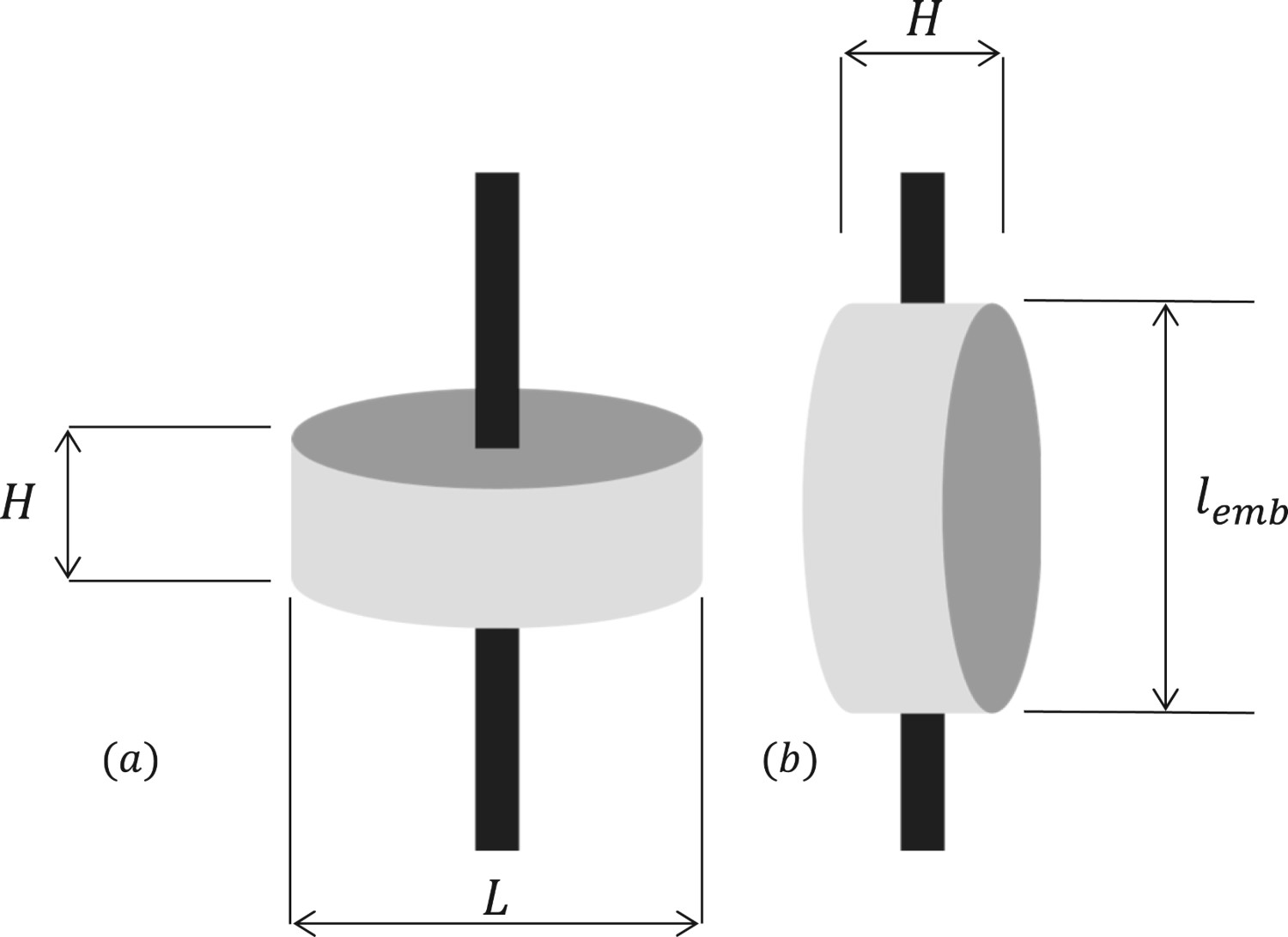
Despite being referred to as ‘microbond’ test, the quantity of material contained within these microdroplets actually falls within the nanogram range, particularly when dealing with fine fibres like CF. This opens up the potential for scaling problems that can lead to unexpected and substantial disparities in the properties and performance of these droplets when compared to larger-scale specimens even with similar thermal and environmental exposure [318]. In an infrequently referenced study, Haaksma and Cehelnik [319] noted several problems with microdroplet specimen preparation. These issues suggest potential challenges in scaling up the polymerisation process for thermosetting resins at this size. Given that the droplets were not fully cured, the researchers concluded that achieving an IFSS value was ‘impossible’ using the cure cycle conditions employed for SFFT specimens. In the context of epoxy systems, it has been demonstrated that the performance of thin specimens undergoes notable variations in comparison to bulk specimens, primarily attributed to internal stress experienced during the curing process [320]. This observation holds relevance for both microbond and SFFT specimens. Thomason [318] elaborated on the scaling issues in the specimen preparation and data interpretation of the microbond test, for both thermosetting and thermoplastic droplets. An extensive evidence has demonstrated the strong reliance of microbond test results on the properties of the microdroplet, including its modulus and 
Droplets exhibit lowered 


The interfacial properties are affected by cure kinetics. The volumetric shrinkage of the resin during the cool-down results in residual compressive stress on the fibre. A larger temperature difference results in higher compressive stress and hence a larger IFSS. Thomason and Yang [323] evaluated the temperature dependence of the IFSSapp in a GF-PP system by performing the microbond test under controlled temperature in a thermo-mechanical analyser. They reported an inverse dependence of the IFSSapp with the testing temperature, explained by the higher radial residual compressive stress at lower testing temperatures.
The effects of fibre sizing removal and the addition of coupling agents on the IFSSapp enhancement were investigated in [255] for a range of recycled CF-PP systems. Lastly, to envision the workload, the number of tested specimens for each matrix material ranged from 50 to 151 [280,306,324], and the reported success rates were 51% (excluding the specimens that failed through fibre failure) [255], 95%, 72%, 38% for the 


Data reduction schemes
Basic approach
A simplistic apparent (also known as overall, mean, or average) IFSS is defined as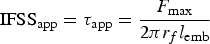


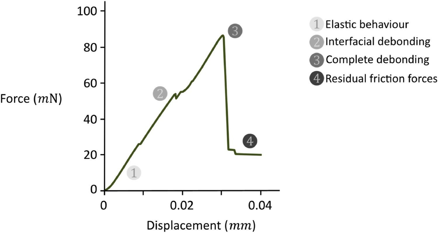
In addition to the probable fibre break (leading to a sharp peak succeeded by a force drop), droplet slippage is another likely undesired incident within the experiments, displaying frictional resistance with no sharp peak on the 
The 


Other stress- and energy-based approaches
Reportedly [324], provided that 


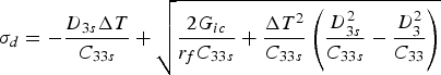
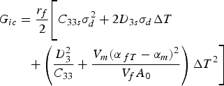
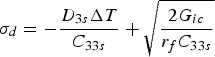


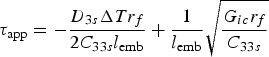
The deficiency of 


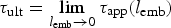


Concerning the effect of friction throughout debond propagation, cohesive and frictional components of the microbond test were extracted by both stress- and energy-based criteria in [325]. Both frictional and residual thermal stresses regulate stable crack propagation. An energy-based debonding criterion (

The most eminent inconsistency between different analyses of the microbond/pull-out tests is concerned with the point where the fibre enters the matrix (see Figure 25). A linear-elastic FEM yields a singularity at this point [334]; variational mechanics gives zero shear stress [328,335]; SLM estimations fall in between. However, a bit farther from this point, at a distance of Interfacial shear stress profiles along the fibre embedded length in a microbond test, predicted by three different approaches – the 


An alternative to the 


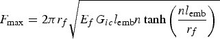
Penn and Lee [256] used a more precise energy-based criterion by considering a pre-crack (negligible compared to Comparison of the energy-based models predictions of the force-embedded length with the experimental data for the microbond test of GF-epoxy (redrawn from [340], with permission from Elsevier).
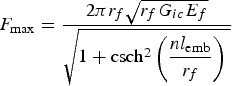


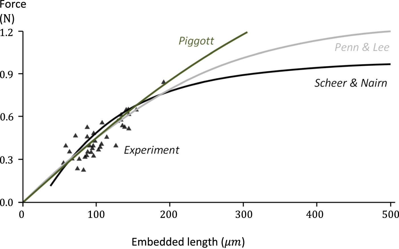
The three different methods of determining the ‘traditional’ method based on the ‘alternative’ method based on the ‘indirect’ method based on An idealised force-displacement curve of a pull-out test. Segment 


The interfacial parameters (


Since 


The 
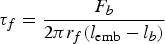

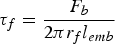

Zhandarov et al. [332] assessed the correlation between the 


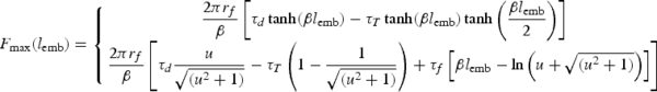


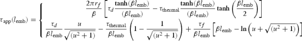
with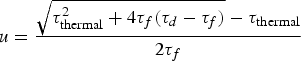
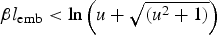

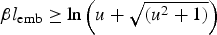


The Nairn analytical model for the pull-out and the microbond test [276], representing the 
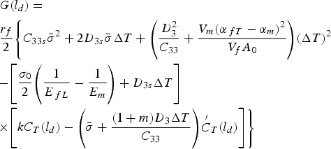


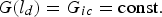
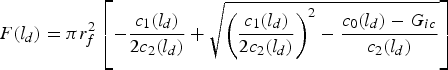


Adhesion pressure
The interfacial normal (radial) strength (IFNS, 


Reported values for adhesion pressure and work of adhesion [342].


Bear in mind that Interfacial stress state along the embedded length in the variational mechanics model [328] for the intact interface up until the debond initiation: at the point of entry, the shear stress, 


An imperfect interface (two-stage debonding) presumably occurs when there is no confined debonding front (i.e. no sharp crack tip), and the full debonding occurs after this fuzzy region formation [343]. Based on a multilinear bond law [344,345] and its modified version [346], the force–displacement curve of an imperfect interface can be modelled and compared to the experimental force–displacement curves. These models are the most comprehensive but experimentally impractical ones, as they contain an excessive number of fitting parameters (up to 5) [279].
Numerical methods
Theoretically, the debond initiation in the microbond test occurs in pure mode I (same as the variational mechanics approach prediction [328]: 
Concerning the effect of meniscus and blade separation (microvise angle) on the stress distribution, Ash et al. [281] developed an axisymmetric FE model. Rather than a cylindrical, spherical or elliptical configuration, a more accurate representation of the droplet geometry (Carroll's method [285]) was fed into the model. Altering the droplet geometry and microvise angle caused a substantial change in the stress distribution at the contact point but not much in the average IFSS. The yield zone along the interface shrinks as the gap width (see Figure 20) widens, confirming the experimental results with overestimated IFSS values when the gap width is too wide [347].
Tailoring the droplet geometry to a cylinder (with the same volume and length), based on SLM, inaccurately describes the shear stress by reaching a non-zero value at the end of the matrix cylinder [335]. The variational mechanics approach overcame this problem by employing a cylindrical geometry and an adjustable parameter [335]. The FEM approach with either an ellipsoid [338] or a spherical geometry [293] provided a realistic representation of the interfacial stress state but was hampered by the substantial time required to generate a mesh for a droplet. Solving for interfacial shear stress, Mendels et al. [348] equivalent cylinder analytical solution was identical to the numerical discretisation of the droplet profile method if the analytical embedded cylinder length is confined to the two inflection points of the droplet profile. Both approaches were based on a 2D stress transfer model elaborated in, similar to the Cox model but did not require any adjustable parameter [292]. The equivalent cylinder radius, 
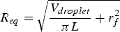

Pandey et al. [339] in their 2D (axisymmetric) and simplified 3D (no interphase region) FEMs, assessed the major effects of blade separation and geometry (i.e. blade tip radius) on the interfacial stress distribution. The 2D model results in an axisymmetric stress distribution along the interface and incorrectly represents the loading by a droplet being pulled through a circular hole in a plate rather than against two blade edges (as in the 3D model). Moreover, the implemented friction between the blade and the droplet surfaces in the 3D model did not affect the stress distribution, but the maximum stress was 5% above that in the frictionless 3D model. For an elastic droplet, the 2D model was favoured over the 3D model owing to being less resource-intensive yet adequately accurate. However, for an elastic-perfectly plastic droplet case, the 2D model overestimated the stress outside the contact area [339].
Kang et al. [306] experimentally showed that the apparent IFSS increases with increasing 


An ‘enhanced’ microbond test, by integrating Fibre Bragg Grating (FBG) sensors to monitor local fibre strain, enables outputting the strain on top of the conventional test output, 
Schuller et al. [295], simulating the debonding by a 2D linear-elastic axisymmetric FEM, highlighted the significant effect of the interfacial friction on the peak load and crack propagation stabilisation. A comprehensive FEM, highlighting the significance of considering the thermal residual stresses and interfacial friction throughout the debond propagation and upon post-debonding, was developed in [298] with an elastic matrix and a bilinear mixed-mode CZM. Their results reveal that the 


To summarise, although meticulous FE models are promptly essential to the field, the recent FE models, although missing some features, have been useful in providing guidelines for practical executions.
Laser Raman spectroscopy
LRS was applied to HM CF-epoxy microbond specimens (HM CF exhibits a distinct Raman spectrum), and the results were compared to those of the conventional microbond tests in [336]. The stress-induced Raman band shifts enable precise acquisition of the strain variation along the fibre embedded in epoxy. The interfacial shear stress profiles were obtained using the fibre axial strain distributions, 


Conclusion
The key advantage of the microbond test, apart from its applicability to almost any fibre–matrix system, is the possibility to evaluate the force upon debonding. The cohesive or adhesive nature of the interfacial failure can be ascertained via SEM examination of the fibre surface after failure. As a major drawback, the stress state in the droplet alters both with its size and the position of the contact points between the loading blades and the droplet. Moreover, the debonding force is a function of the fibre embedded length, and with thin fibres such as CF, GF and Kevlar (


The reliability of the 


Typically, the microbond method gives lower IFSS values than other test methods, such as the SFFT, as reported in [293] (26–37% less). This is explained by either meniscus failure [281] or altered droplet mechanical properties compared to the bulk polymer. The latter occurs through the loss of the curing agent (hardener) by diffusion and evaporation/vaporisation in the case of thermosetting matrices (lowered 

Table A4 summarises the reported interfacial properties acquired by the microbond tests. The variation in the reported properties stems from a wide range of issues, including: the geometry of the droplet [337], inaccuracy of the measuring equipment (in measuring force, displacement, and fibre diameter), position of the loading knives (separation distance or gap width/size from the fibre surface) [282,291,347], micro-size effects in the contact region with the microvise tip [306], fibre–matrix contact angle [308], droplet cure cycle and the volatility of the hardener [307], fibre roving section [294], uncertainty in determining the embedded length (surface) [294].
At the initial stage of the pull-out or microbond tests, the failure mechanism involves normal separation (mode I) of the matrix from the fibre and a fuzzy failure front propagation [10,98,209,343,355]. Consequently, the resulting high IFSS values can conceivably be compared with the tensile strength of the polymer matrix.
It is of utmost importance to exercise meticulous caution to ascertain that any observed effects in the microbond test truly reflect the real characteristics of interface behaviour, rather than being distorted by scaling issues during specimen preparation and testing. The literature has previously documented microscale curing challenges in thermosetting resin systems even before the introduction of the microbond test [356]. These concerns have been acknowledged as areas for improvement in some of the earliest critical reviews of microbond [319] and micromechanical [293] testing methods. However, there has been limited substantial effort to directly address this issue, despite the growing adoption of the microbond test. Bryce et al. [357] have presented compelling evidence of substantially lower levels of curing in microdroplets of various epoxy systems. As a result, it has become impractical to perform the microbond test on specimens with identical curing histories as macroscale FRPs. For instance, obtaining representative microdroplet specimens has only been achievable through resin curing conducted under an inert atmosphere. Consequently, great care must be taken to ensure that the observed effects in the microbond test genuinely reflect the characteristics of the real material rather than artefacts stemming from specimen preparation [358].
Typically, the IFFT and friction force can be approximated from the load–crack length or load–displacement hysteresis curves in the presence of a constant friction shear stress and for load-controlled crack growth. Moreover, the results obtained for IFSS may vary due to the degradation in thermoplastics [359], relatively small changes in testing temperature [323,360] and slight variations in the stoichiometry in thermoset systems [361]. There is no singular standardised remedy for these challenges, and each fibre–matrix combination may encounter unforeseen and unpublished specimen preparation artefacts that can have a far more substantial impact on the obtained IFSS values than any material-related effects being investigated [358].
Determining a mixed-mode dependent IFFT is challenging. Reportedly [275], for the microbond test and not-too-small crack lengths, the mode-mixity remains nearly constant and corresponds to a dominating interface shear load which shifts towards mode I loading by a larger ratio of friction load to the applied load. Nevertheless, it appears that it is not feasible to modify the mixed-mode angle to a predetermined value.
Push-in/-out tests
Push-in test
The push-in/-out test, also referred to as fibre push-down, micro-compression, indentation, micro-indentation or nanoindentation test [362], is an in-situ micromechanical test for interfacial characterisation of the multi-fibre composites. This method is based on axially pushing down a single fibre over its cross-section with a micro-/nano-indenter (see Figure 29). These indenters only differ by the size of the indenter tip (see Figure 36) and the sensitivity of the measurement system [363]. Interfacial failure will occur due to high shear stresses, owing to the elastic and thermal mismatches between the constituents. This test is susceptible to the matrix material properties and the constraint introduced by the adjacent fibres [364] and is less frequent than the aforementioned single-fibre test methods. This test is suitable for use on actual FRP laminates, either before or following degradation while in service. Schematics of fibre push-in test.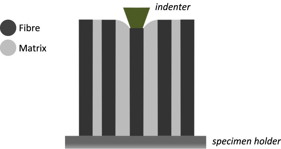
Push-in data reduction schemes
The argument on the relevance of the interfacial testing method to a ‘real’ composite laminate overshadows the single-fibre composite (‘model’ composite) tests, such as the SFFT, pull-out and microbond tests. The interfacial stress state of the debonding fibre is affected and complexified by the presence of the neighbouring fibres. The deficient resemblance of the single-fibre tests highlights the bulk composite test methods for evaluating the interfacial parameters in the presence of the adjacent fibres.
To improve the accuracy of the push-in test, Kalinka et al. [365] designed a highly stiff test apparatus featuring an indenter with a high positioning resolution (


Kharrat et al. [370] attained ‘reduced’ indentation curves where the elastoplastic indentation of the fibre surface, 


In the absence of debonding, the initial load–displacement response is linear (can be confirmed by unloading at the end of the suspected range), and the transition towards non-linearity indicates debonding initiation and/or matrix plastic deformation. Following a stress-based approach, generally, a simplified SLM [370,371] can be used for analysing the results. Therefore,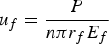


Molina-Aldareguia et al. [373] proposed a micromechanical FE model of the push-in test with interfacial cohesive elements. They revealed that the prevalent analytical models are valid when the indented fibre is relatively far from the adjacent fibres ( Typical (ideal) load–displacement curve of a push-in test of a CF-epoxy composite. Succeeding the initial region, corresponding to the zone with imperfect contact between the indenter and the fibre, the linear segment (with stiffness 


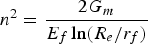


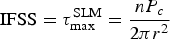


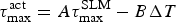


To consolidate the simplified FEM of Rodriguez et al. [374] (indented CF amid six adjacent fibres), Wang et al. [377], similarly in their 3D RVE of randomly packed fibres, assessed the effect of fibre and matrix thermo-elastic mismatches on the indentation response and the quantified IFSS. The FEM-assisted calibration of the standard SLM by including thermal and elastic mismatch leads to


Reportedly [376], for single fibre push-in for CF-epoxy composite slices of about 300 µm thick, the initial damage (possibly matrix plastic deformation) and interfacial failure did not rely heavily on the local fibre density. Moreover, the quantification of interfacial toughness is, however, difficult from the push-in tests, as the debonded area cannot be quantified at the failure loads. Tests on thinner CFRP slices (thickness ∼30 µm) had resulted in full debonding and fibre push-out without fibre failure. However, in thicker slices, the fibres showed initial indenter imprints on their surface and the load-displacement curves exhibited an increasing hysteretic behaviour before debonding. Furthermore, analysing the cyclic load-displacement curves can furnish information on the elastic-plastic and hysteretic (debonding) energy contributions [376].
Desaeger and Verpoest [372] examined the push-in test's credibility, limits and possibilities. Presuming that debonding occurs when the interface crack is larger than a quarter of the fibre circumference, valid experiments were those with 

It is beneficial to track and analyse the interfacial changes rigorously. A time-lapse X-ray CT scanning can elucidate the progress of composite degradation. Watanabe et al. [378] used nanoscopic synchrotron radiation X-ray computed tomography to investigate the crack initiation and propagation in CFRPs under a push-in test at a spatial resolution of 50 
Push-out test
The push-out (or push-through) test was instigated by Marshall [368] to assess the interfacial properties of ceramic matrix composites (CMC). The push-out test is to micro-indentation what the microbond test is to the pull-out test [252]. In a push-out test, an individual fibre of a thin ( Fibre push-out test: (a) schematics of the test (specimen may be glued on a holder to reduce the compliance in the load-displacement curve and mitigate the specimen bending during testing), (b) the three-stage mechanical preparation process of the specimens (redrawn from [367], with permission from Elsevier), SEM images of the specimen (c) before the test, and (d) and (e) after the test (taken from [379], with permission from Elsevier). Load–displacement curve for a push-out test: (a) with distinct four stages: 
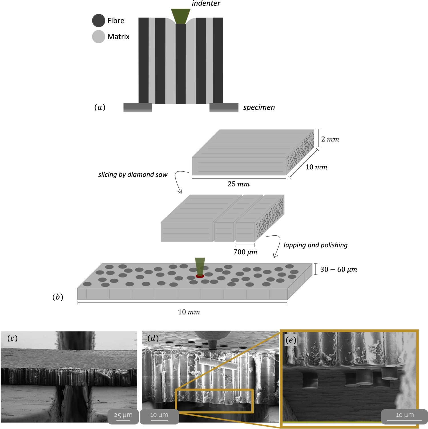
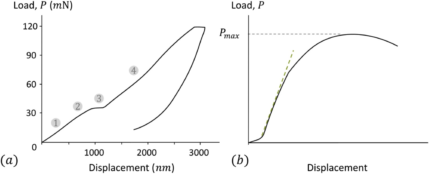
The individual fibres should be selected randomly (a minimum of 20 fibres with similar cross-sectional areas) for each push-out specimen [367]. However, if the matrix material is poorly translucent, e.g. in the case of CF-PPS, the fibre selection might be practically challenging [382]. Furthermore, to minimise the effect of polishing on the results, a similar polishing quality has to be achieved for all specimens [372]. There are two main specimen preparation routes. The conventional push-out test specimens, using a lapping/polishing method (also known as free-standing samples), exhibit excessive geometric nonlinearities (rather than material nonlinearity), significant compliant response, and large scatter and boundary conditions irregularities. In addition, this sample preparation approach is likely to lead to fracture during the grinding step. Although thickening the sample may reduce the compliance artefacts, it can lead to unintended failure modes such as fibre breakage. Alternatively, femtosecond laser-machined specimens (cave specimens) are free of such flaws and are more suitable for an in-situ SEM-based push-out test. Reportedly [383], femtosecond laser machining reduces the heat diffusion into the adjacent material, resulting in high-quality machining with minimal heat-affected zone or microstructural disruption.
Furthermore, the FEM force–displacement curves are more in line with those of the cave specimens. This is due to complications in achieving precise contact boundary conditions in free-standing specimens, while cave specimens exhibit consistent boundary conditions that can be more realistically replicated in an FEM [379]. A sensitivity study [383] for the CF push-out test indicated that a membrane thickness below 


Reportedly [384], the slope of the test is dominated by the position of the fibre inside its bundle or, in a broader sense, by the stiffness of the surrounding material. The deviation from the initial linear behaviour in the load–displacement curves (see Figure 34), associated with the debonding onset, could emerge at different load levels depending primarily on the loading rate and the temperature. This non-linear region, governed by the viscoelastic phenomena, is classified as the intermediate regime that separates the cohesive-dominated and the frictional regimes [385]. Regarding the effect of loading rate and temperature on the push-out test of CF-epoxy systems, both IFSS and stiffness increase with increased loading rate and decrease with increased temperature. The time-dependent response is more evident for experiments performed at high loading rates or elevated temperatures [386]. Representation of the estimated debonding energy (light) and work of friction (dark) on the force–displacement curve of a push-out test. A stable crack growth takes place between phases 


Push-out data reduction schemes
The two main methods to assess the interfacial bond quality are extracting the stress-based IFSS [368] or following an energy-based approach in determining the IFFT [274,365,366,382,387]. The mean stress analysis yields constant interfacial shear stress as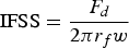

Ideally, for a comprehensive model for interfacial debonding, the debonding energy and the energy associated with friction are separated. The frictional energy part can, in certain cases, persist, whereas the debonding energy disappears when the fibre is fully debonded. For instance, the debonding energy ( Various energy contributions to a cyclic push-out test for determination of the IFFT: the elastic energy corresponds to the integral of the unloading curve, the work of friction is determined by the area enclosed between the unloading and reloading curves, the plastic separation energy is represented by the area between the loading curve and the subsequent reloading curve, and the total separation energy refers to the cumulative energy input into stable crack growth (redrawn from [367,384], with permission from Elsevier).

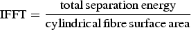


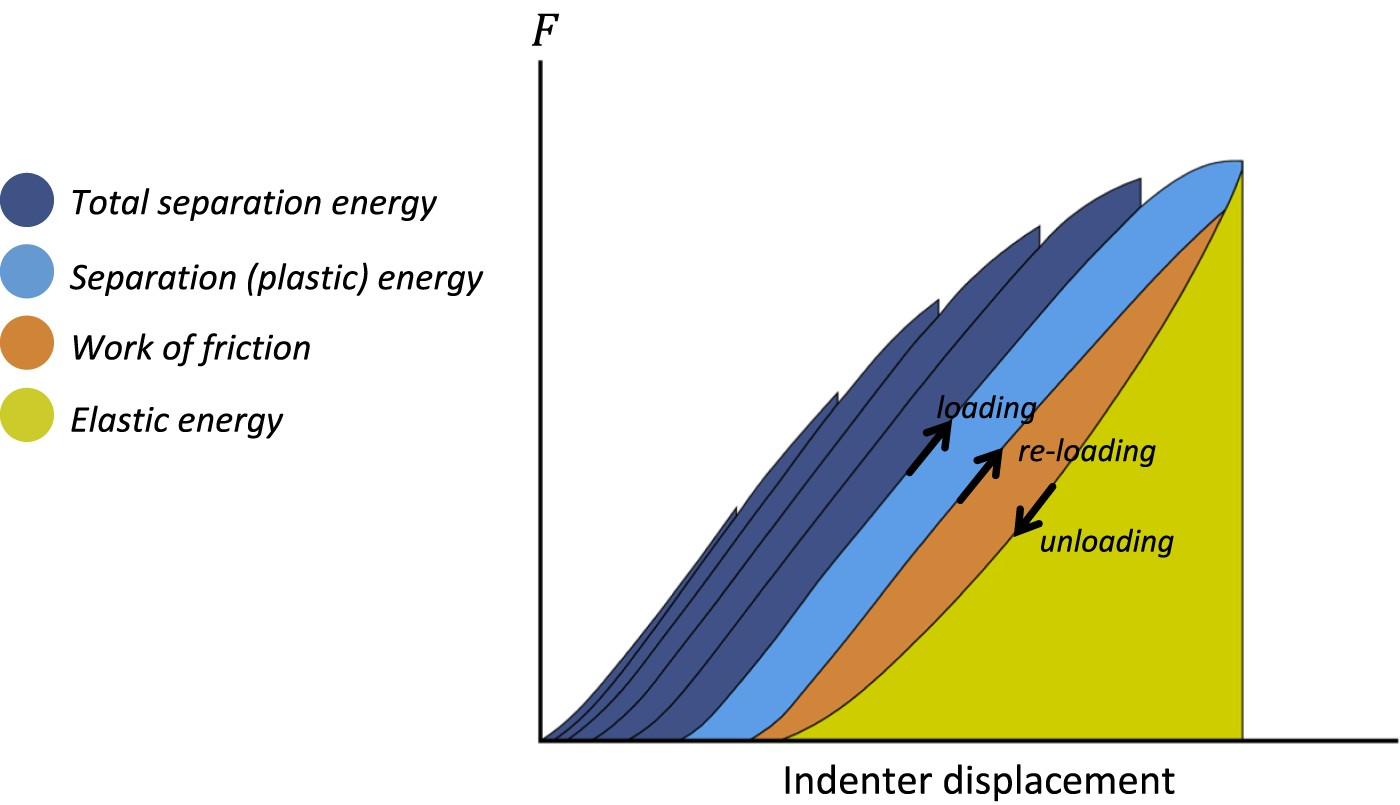
During the push-out test, the interfacial debonding occurs through mode II crack propagation [274]. The crack initiation and propagation in a push-out test were modelled using a CZM in an axisymmetric model [389]. A bilinear traction-separation law was used to describe the frictional sliding arising between the crack faces based on the Coulomb friction law. Such an approach implicitly captures the frictional sliding behaviour within the traction-separation law rather than explicitly modelling it through contact algorithms. This prohibits the development of new crack faces and may not be fully representative of the physically observed frictional sliding between the debonded surfaces [389]. Assuming an elastoplastic material for epoxy resin yields a better agreement between experimental and numerical force-indenter displacement curves than the linear-elastic matrix model [381].
Indenter tip geometry
Figure 36 illustrates the typical indenter tip geometries for the push-in and push-out tests. Mueller et al. [388] carried out SEM and AFM on the front and backside of the samples in their interrupted ceramic matrix composites push-out tests. The overestimated interfacial properties using a Berkovich (pyramidal) indenter tip were justified by the premature loading of the matrix adjacent to the fibre before the push-out development. This can be avoided by using a geometrically viable flat-end indenter tip [388]. Desaeger and Verpoest [372] reported occasional and frequent splitting of GF and CF, respectively, by a pyramidal tip. This was avoided by replacing it with a round semi-spherical tip. Generally, indenter tips with a larger radius of curvature than 


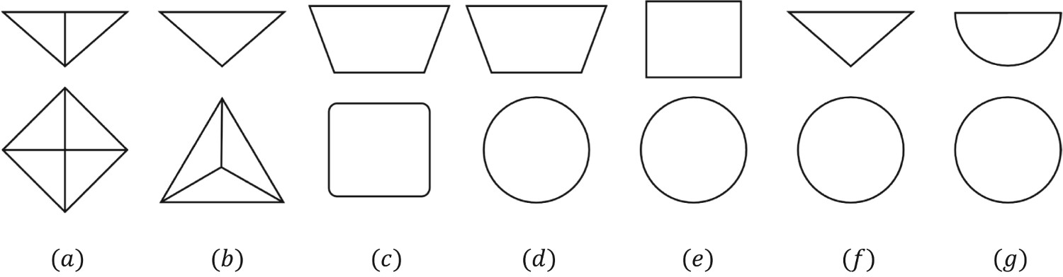
Sakharova et al. [390], in their 3D numerical simulations, concluded that force–indenter displacement responses are independent of the friction coefficient value (0.04–0.30) between the various indenters and the indented material. The hardness and modulus were varied by a maximum of 1.3% in models with and without friction [391]. To determine the indented specimen's elastic modulus and hardness, one might encounter the geometrical correction factor, 


Based on the geometrical limitation of the indenter, the expected push-out protrusion length can be identified, e.g. 1–1.2 

Comparison of the two methods
For both push-in and push-out tests, a nanoindenter axially pushes an individual fibre in the cross-section of a specimen until interfacial debonding occurs. Regarding the sample preparation, the push-out test involves laborious effort in fabricating a thin membrane of the composite (thickness of ∼50 


Some studies have compared the results of both methods for identical material systems. Ramanathan et al. [382] investigated the effect of surface modification on the interfacial frictional stress and the debond energy for various CFs via both push-in/-out tests (see Table A5). Their results show that surface-activated CFs with basic oxides, produced by the thermal treatment method, yield higher IFFT values than acidic or unmodified CFs. Medina et al. [375] have reported analogous values of the IFSS in GF-epoxy (+CNT) composites evaluated by both push-in and push-out tests.
Conclusion
The application of the nanoindentation method in FRPs has been rapidly growing since the early 2000s [363]. The theoretical models governing both pull- and push-out tests share similarities, except that due to Poisson's effect, lateral contraction of the fibre is observed during pull-out tests while lateral expansion of the fibre is observed during push-out tests. The small size of the nanoindenter tip enables direct measurement of the elastic properties of the constituents. For instance, the matrix behaviour can be directly assessed in the matrix-rich regions of the prepared specimen, where the influence of neighbouring fibres is negligible. In addition to the axial and radial properties of individual constituents, their interfacial properties can be determined. It is a better practice to prepare the specimens from the ‘real’ (i.e. in-situ) composite due to the higher resemblance to the polymerisation and manufacturing history of actual FRPs [384]. With this method, the interface degradation can be studied for composites which have already been in service [88].
However, for some fibre–matrix systems, interface fracture is extremely difficult to detect; some fibres split before interface fracture and locating the indenter in the middle of the fibre of interest requires a very accurate positioning system. More optimised and contemporary testing procedures must be established (similar to [372]). Moreover, the success of the tests is closely linked to the polishing quality of the specimens. Continuous stiffness measurement within the instrumentation is crucial for materials with time-dependent properties, such as polymers.
One of the main limitations of the fibre push-out method is the lack of in-situ observations, as the fibre is fully embedded in the matrix. Consequently, there is limited knowledge about how defects in the matrix, such as voids, inclusions, and chemical segregations, or on the fibre, such as surface roughness, non-uniform coatings, and premature oxidation, affect the variability of interfacial property measurements. Even if tested in an SEM, direct visualisation of crack propagation or the dominant failure mechanism is not possible. Additionally, traditional fibre push-out tests often yield a high degree of data variability, which can be better understood and mitigated through the use of innovative in-situ techniques [392]. Moreover, studies on the development of piezoelectric push-out devices have primarily focused on device production, with insufficient attention given to assessing the accuracy and analysing material failure. The accuracy of piezoelectric push-out devices still requires further examination and confirmation [393].
Further studies are required to quantify the IFSS of nanotube-reinforced polymers through push-in/-out techniques [363]. Additionally, surface roughness and adhesive effects between the indenter tip and the specimen surface need to be assessed for their significance. Reportedly [293], the IFSS almost doubled with the surface treatment as measured with SFFT, while the micro-indentation technique reflected only a 17% increase due to the surface treatment. This clearly shows that more work is needed to address this discrepancy. To date, an FE model-assisted push-in/-out technique, considering the intricate interplay of the constituents, has proven to be a more appropriate method for measuring interfacial properties since the test is carried out in-situ on FRP bulks.
Table A5 presents the reported interfacial properties of CF or GF in thermoset or thermoplastic matrices measured through both push-in/-out methods. Overall, the push-in/-out yields slightly higher IFSS values compared to the previous three micromechanical tests. This can be related to the existing neighbouring fibres, different residual stress states or inherent to the indentation test setup.
Infrequent test methods
The methods described earlier are the most widely used ones. However, there are also some lesser-known yet notable alternatives that stand out due to their distinctiveness. Note that Broutman and Outwater-Murphy tests provide information on transverse debonding, which sets them apart from other interfacial shear tests.
In the Schematics of the infrequent test methods: (a) three-fibre test [398], (b) Broutman test [399], (c) single-fibre peel test [400], (d) Outwater-Murphy test [401], and (e) fibre-stretching test [326]. Note that by not applying a glue droplet on the right side of the fibre in (e), the configuration will portray the microbond test setup used in [237] (subfigures are redrawn from [279] for (a) and (b), from [400] for (c), from [401] for (d), and from [326] for (e), with permissions from Elsevier).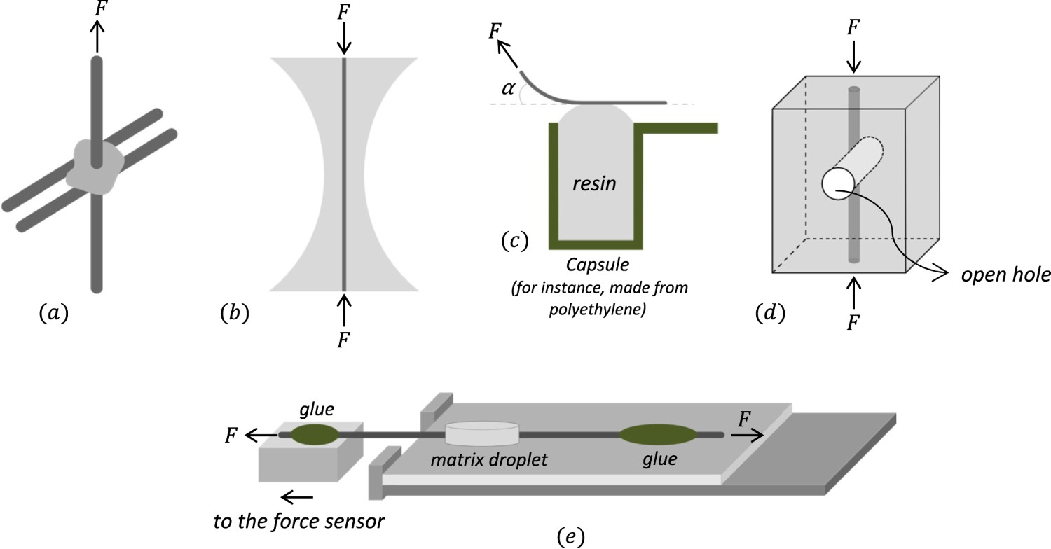
The 


Another unconventional test is the 


The 

Lastly, during a
This phenomenon enables a distinction between the friction associated with interfacial roughness and that due to the residual stresses. The substantial size of the seating drop indicates that interfacial roughness can account for a large portion of the frictional sliding [414]. This sort of information is particularly beneficial for analysing the debonding conditions and, more precisely, what happens just behind the debond crack tip [415]. No seating drop was observed for CF-PEEK in [416], suggesting a plastic deformation and abrasion of the frictional surfaces during push-back, drastically reducing the topological matching at the initial fibre position. The single-fibre push-back test is predominantly used for CMCs and metal matrix composites.
Concluding remarks and outlook
The mechanical properties of FRPs are closely related to the fibre–matrix interfacial properties. Numerous micromechanical test methods have been proposed to characterise the fibre–matrix interface. Still, there is an ongoing debate as to which method is the most precise, reliable and relevant. Uncertainties in the obtained interface characteristics and interlaminar shear strength lead to unreasonably high load safety factors and overweight structures, diminishing the value FRPs provide [417]. It is noteworthy that the interfacial properties of the same material system obtained via different test methods are not comparable. This is primarily due to the fact that the local stress fields brought about by a particular test arrangement are not identical and are not considered accordingly in the respective data reduction schemes. Figure 38(a,b) demonstrates the spread and skewness of the reported IFSS values for carbon-epoxy and glass-epoxy systems, respectively. The reported high IFSS values from SFFT, microbond or pull-out test, exceeding the matrix shear strength (outliers in Figure 38), presumedly were correlated with a complicated interfacial failure pattern rather than pure interfacial shear failure. Figure 39(a) indicates that a stronger adhesion at the fibre–matrix interface tends to increase the fracture toughness values in carbon-epoxy systems. However, for glass-epoxy systems, the existing scatter in the reported values (Figure 39b) prohibits drawing conclusive judgements. Moreover, the inconsistency among various tests also reveals itself in the IFSS ratio of treated to untreated fibre. This indicates that each technique reacts differently to the conditions prevailing at the interface/interphase. Furthermore, controlling the test environment to avoid any influence of external factors such as temperature and humidity and the need for advanced imaging techniques are among the common challenges faced by all the discussed methods. Reported IFSS from microscale interfacial characterisation tests: (a) for carbon fibre-epoxy systems, and (b) for glass fibre-epoxy systems. The cross within the box indicates the mean, and the vertical line shows the median.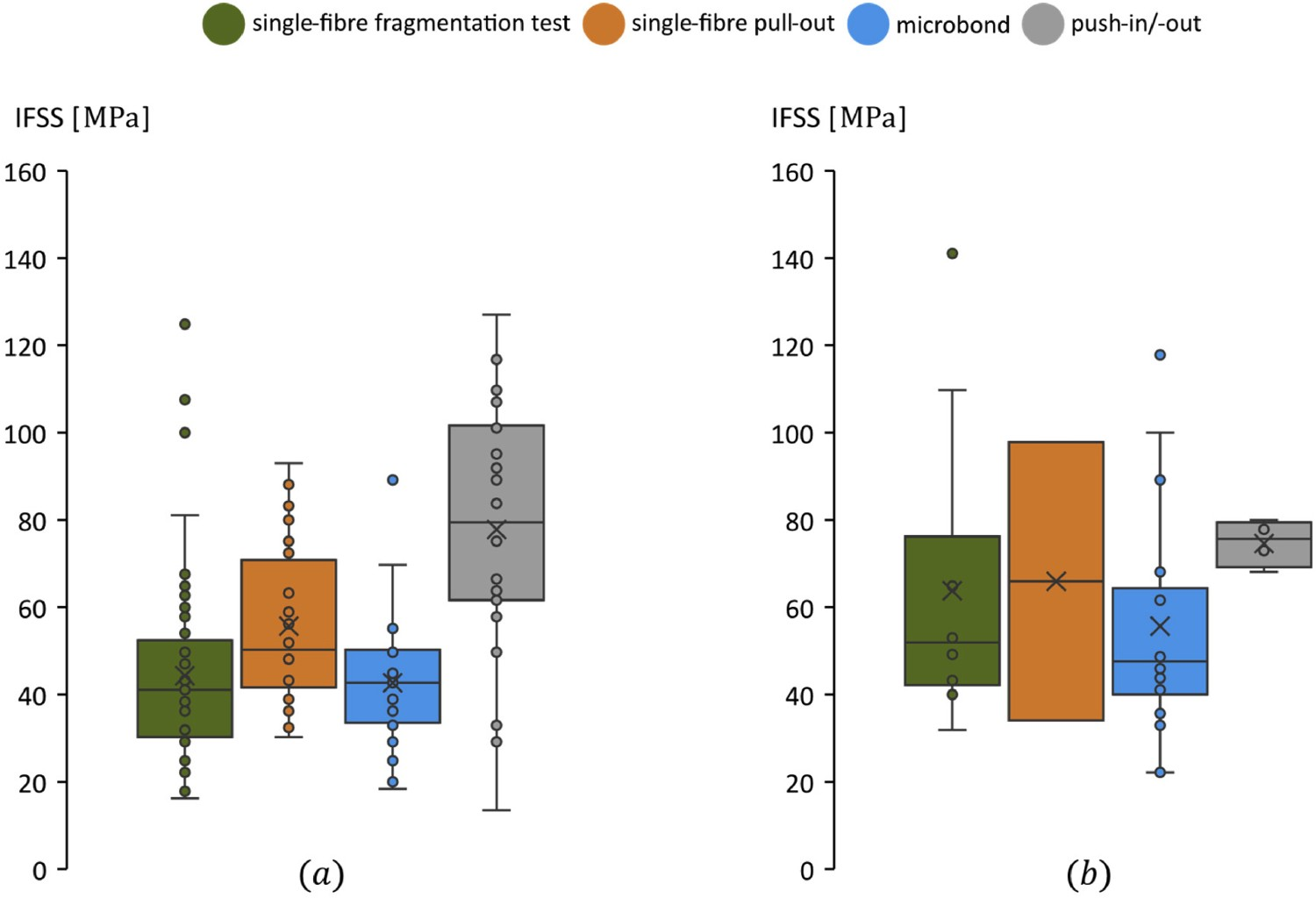
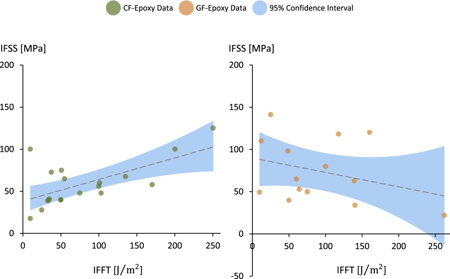
There is a scarcity of literature that discusses a quantitative process utilising basic SFFT or MFFT data to estimate the fracture toughness of a UD laminate (the transition from micro- to mesoscale). Micromechanical models for interlaminar and translaminar fracture toughness would require the IFFT and friction coefficient, but such models remain rare. Varandas et al. [420] is the only micromechanical model for mode I interlaminar fracture, but unfortunately does not predict the mode I interlaminar fracture toughness and just focuses on crack migration. Pimenta and Pinho [421] developed a micromechanical model to predict the translaminar fracture toughness, and they indeed revealed that IFFT and friction coefficient are vital parameters. To the best of our knowledge, no micromechanical models exist for the mode II or III interlaminar fracture toughness. We, however, believe the development of such models is now possible and will start appearing in the coming years thanks to the increased computational power available for FE analysis.
An extensive set of investigations have been conducted to determine the relevance of fragmentation testing to real FRPs. These studies have revealed that even a slight change in the interface, which may account for only 1% of the total weight of an FRP, can lead to significant differences in compressive strength and notched fatigue life, with variations of up to 50% and two orders of magnitude, respectively [422]. Furthermore, it is envisaged that the interface greatly influences the long-term performance of such systems, especially life and retained strength under cyclic loading and/or in the presence of aggressive environments such as high temperature and corrosive chemicals [423–425].
Further complications arise when attempts are made to correlate the results of the fragmentation test with the mechanical performance of high 
While the reviewed methods may not give an absolute value, they can elucidate the interfacial failure mechanisms/characteristics and reinforce our comprehension of FRPs’ failure. Accordingly, frequent collaborations and multidisciplinary round-robin tests are required to assess the deficiencies in interfacial studies. Absent or inadequate standards are another contributing factor to the observed discrepancies. It is difficult to strengthen the interface reliably without a reliable interfacial characterisation method. Numerically, coupling molecular dynamic simulation, FEM and DEM for multi-scale interfacial investigations would be worthwhile. Some novel tools, such as digital volume correlation on in-situ synchrotron radiation computed tomograms, which have proven their practicality in FRP failure analysis, can be exploited for quantifying the full-field volumetric displacements/strain fields in composites.
There are several gaps in current knowledge about the fibre and matrix interface characterisation in FRPs that could be addressed by future research. Here are some thoughts and suggestions for such research: Developing new characterisation techniques: Current characterisation techniques have limitations in terms of their sensitivity. Developing new techniques that can provide more detailed information about the interface would be valuable. For example, advanced microscopy techniques such as high-resolution transmission electron microscopy (HRTEM) and scanning transmission electron microscopy (STEM) can provide detailed information about the interface structure, chemistry and bonding. To obtain scientifically valid and statistically significant results from a large number of specimens, it is essential to have customised equipment for preparing, testing and analysing the specimens. Automated processes in these areas are expected to expedite fragmentation testing, eliminate manual errors, and help establish a standard protocol for measuring IFSS [199]. Investigating the effect of interface properties on mechanical behaviour: While it is well established that the fibre–matrix interface plays a critical role in determining the mechanical properties of composite materials, the relationship between interface properties and mechanical behaviour is not well understood. Future research could focus on investigating the effect of interface properties such as interfacial bonding strength, adhesion and interfacial chemistry on mechanical behaviour. Developing new materials for the interface: The properties of the fibre–matrix interface are strongly influenced by the chemistry and structure of the interface region. Developing new materials that can enhance the interface properties, such as coupling agents and interphase materials, could improve the overall mechanical performance of FRPs. The key focus of future developments in CT for interfacial studies in FRPs is expected to comprise: improved imaging technology and resolution, more advanced algorithms for image reconstruction and processing, and increased collaboration between experimental and computational researchers. Another area of interest is the use of in-situ CT, which allows for the observation of dynamic processes occurring at the interface under various loading and environmental conditions. This will require the development of specialised experimental setups that can withstand these conditions and maintain the necessary imaging quality [426]. Developing improved micromechanical models to accurately predict interlaminar and translaminar fracture toughness. By combining these models with other micromechanical models for transverse cracking, it is possible to provide mesoscale models with the necessary information to predict the macroscopic behaviour of multidirectional laminates.
Footnotes
Disclosure statement
No potential conflict of interest was reported by the author(s).
References
Supplementary Material
Please find the following supplemental material available below.
For Open Access articles published under a Creative Commons License, all supplemental material carries the same license as the article it is associated with.
For non-Open Access articles published, all supplemental material carries a non-exclusive license, and permission requests for re-use of supplemental material or any part of supplemental material shall be sent directly to the copyright owner as specified in the copyright notice associated with the article.