
Abstract
In the last five decades, significant advances have been made in developing alloys for space power systems for spacecraft that travel long distances to various planets. The spacecraft are powered by radioisotope thermoelectric generators (RTGs). The fuel element in RTGs is plutonia. For safety and containment of the radioactive fuel element, the heat source is encapsulated in iridium or platinum alloys. Ir and Pt alloys are the alloys of choice for encapsulating radioisotope fuel pellets. Ir and Pt alloys were chosen because of their high-temperature properties and compatibility with the oxide fuel element and the graphite impact shells. This review addresses the alloy design and welding and weldability of Ir and Pt alloys for use in RTGs.
Introduction
In the last five decades, several novel and unique alloys have been designed and developed for space exploration. Some of them include iridium (Ir) and platinum (Pt) alloys for interplanetary space exploration.1, 2
Ir and Pt metals, which are both in the Pt group, have high melting points, high-temperature strength, and good oxidation and corrosion resistance. Ir and Pt alloys are chosen for encapsulating radioisotope fuel pellets. This paper reviews the welding and weldability of Ir and Pt alloys used for space applications.
One might wonder what provides electrical power for the spacecraft instruments that are sent on interplanetary exploratory missions for long periods of time. Electrical power is supplied by radioisotope thermoelectric generators (RTGs). RTGs are nuclear-powered generators. In 1954, after the US Congress passed the Atomic Energy Act, scientists explored the feasibility of using atomic energy to power satellites.
3
The idea got a big boost from the work of two Monsanto scientists, Ken Jordan and John Birden, of Mound Laboratory, Ohio, who demonstrated a device that was able to convert heat from the natural decay of the Po-210 radioisotope to electricity. Using the principles of thermoelectricity, also known as the Seebeck effect, they converted the heat from the Po isotope to electricity using thermocouples. The early RTGs used lead telluride-based materials for their thermoelectric elements. Later, thermoelectric elements composed of silicon and germanium were used. The first RTGs3-5 produced only 2.5 Watt-electrical (We). After several design modifications, RTGs have been used on several spacecraft sent on missions to various planets and moons. Current RTGs are powered by plutonia (238PuO2). They provide stable electrical power for instruments on board the spacecraft. Figure 1 shows a schematic of the planets in the solar system, some of which are to be visited by US spacecraft.
A schematic of the planets in the solar system, some of which are to be visited by US spacecraft (Courtesy of NASA/JPL-Caltech)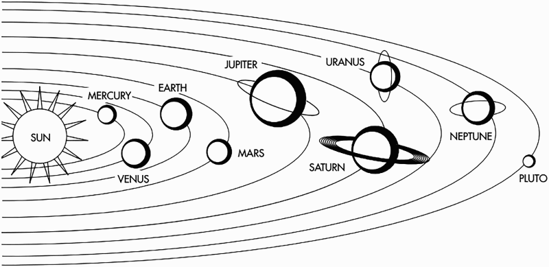
This type of power source is necessary because of the extended time it takes for spacecraft to travel to the outer planets as well as the reduced solar energy available for solar panels at such great distances from the sun. The RTGs are expected to last a number of years as they travel on to Saturn, Jupiter and Pluto. Because of the low temperatures encountered at the great distances of various planets from the sun, in particular, Saturn, the instruments on board a spacecraft have to be heated to normal operating temperatures. For that, heat is produced by Light-Weight Radioisotope Heater Units (LWRHUs), which provide heat through the radioactive decay of plutonia.3-6 A principal design requirement of the US nuclear power systems has always been safety.
Mechanical properties of platinum, platinum alloys and iridium 8
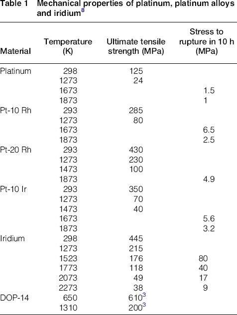
The alloys that were developed for space applications are the Pt-3008
9
(Pt-30% Rh and 8% W)
1
and the DOP-4 Ir alloy (Ir-0.3% W, 30 ppm Th and 40 ppm Al). Further alloy development was required to overcome the temperature limitations of Pt-3008 and improve the high-temperature impact ductility of DOP-4. Thus, DOP-14 (Ir-0.3% W, and 200 ppm Th) and DOP-26 (Ir-0.3% W, 60 ppm Th, and 50 ppm Al) alloys were developed for RTGs. These two alloys were identified for further evaluation because of their high melting point, high-temperature strength, and their compatibility with the RTG's oxide fuel pellet and graphite impact shell. These alloys were qualified for use through mechanical testing, grain-growth studies, materials-compatibility testing, tensile ductility, impact testing and fuel-clad impact testing. The material of choice for LWRHU encapsulation is Pt-30% Rh. Figure 2 shows a general-purpose heat source (GPHS) fuel pellet encapsulated in an Ir alloy.
A general-purpose heat source (GPHS) fuel pellet encapsulated in an Ir alloy (With permission from Welding Journal)
10

The missions of Voyager 1, which flew by Jupiter and Saturn, and Voyager 2, which flew by Jupiter, Saturn, Uranus and Neptune, used Multi-Hundred-Watt (MHW) RTG power systems. The fuel spheres were clad by Ir-0.3%W. Galileo's mission to Jupiter, the Ulysses mission to the polar regions of the sun, the Cassini/Huygens mission to explore Saturn, and the most recent New Horizons mission to flyby Pluto were all powered by GPHS RTG power systems that each produced approximately 288 We at the beginning of mission.
11
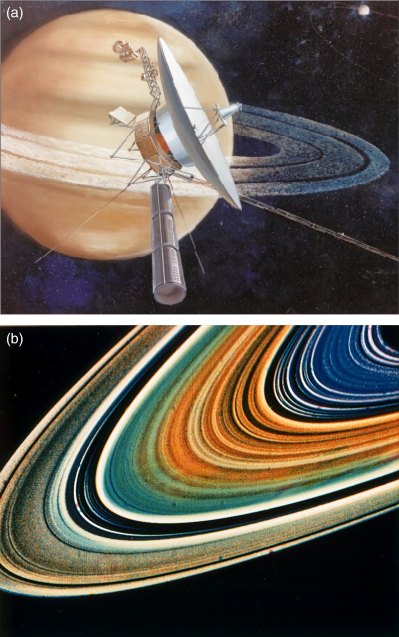
The fuel pellets were clad by DOP-26 with DOP-4 foil components welded inside. Figure 3 shows a sectional view of an 18 cm diam, 40 cm long heat source of the type that was used on the Voyager missions. Figure 4 shows a an artist's conception of Voyager's flyby of Saturn and b the rings of Saturn.
Sectional view of the Multi-Hundred-Watt heat source assembly that was on the Voyager missions (18 cm diam, 40 cm long)
7
a An artist's conception of Voyager's flyby of Saturn and b the rings of Saturn (Courtesy of NASA/JPL-Caltech)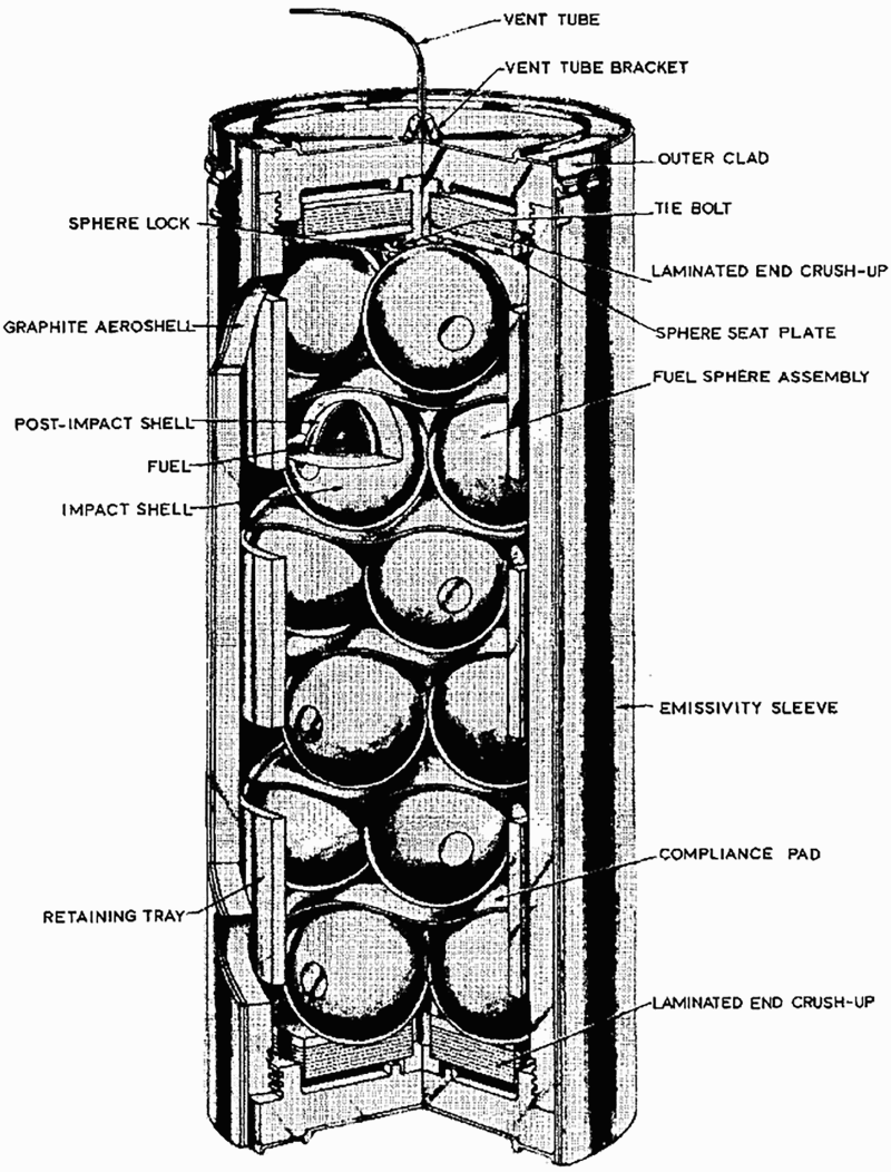
Welding is the technology used for joining the alloy hemispheres (MHW) to form the spherical containers that contain the fuel pellets (currently closed-end cylinders). Weldability is a key issue in the development of these alloys because joining by welding is required to fabricate RTGs. Both Ir and Pt alloys are weldable using gas tungsten arc (GTA) welding and high-energy-beam processes such as electron beam (EB) and laser welding. However, with the addition of alloying elements to improve ductility and strength, Ir alloys become more difficult to weld than Pt alloys. Under appropriate conditions, these metals and alloys can be joined by brazing processes if the correct filler metals are used, but the requirements of the current space probe applications do not allow for brazing to be used. Joining of these metals and alloys and other precious metals is described in detail in Miller and Ohriner. 8
This paper addresses the behaviour of Ir and Pt alloys when subjected to the weld thermal cycle and their welding metallurgy. Since Ir and Pt alloys are used in thin-sheet form, some fundamental issues related to weldability, test development, and the development of weld pool and grain structure in thin sheet are discussed.
The fundamentals
Welding and weldability
The term ‘weldability’ has no universal meaning and is open to interpretation. Recently, David has defined weldability as ‘a measure of the ease with which a metal or an alloy can be welded or joined without degradation that is detrimental to the weldment microstructure or properties during or after welding and for the duration of intended service’.
12
Figure 5 shows a schematic diagram of the interaction between a heat source and the material during welding. The parent metal melts, and its original microstructure is destroyed. The pool of liquid metal that is created solidifies upon cooling. The solidified region is called the ‘fusion zone’ (FZ). Adjacent to the FZ is the ‘heat-affected zone’ (HAZ), a region that experiences heat but does not melt. The material that lies adjacent to the HAZ and that is not affected by welding heat is called the ‘base metal’ (BM) (see Fig. 5). Depending on the alloy, a microstructural gradient from the FZ to the BM may form due to the gradient in temperature.
A schematic diagram of the interaction between a heat source and the material during welding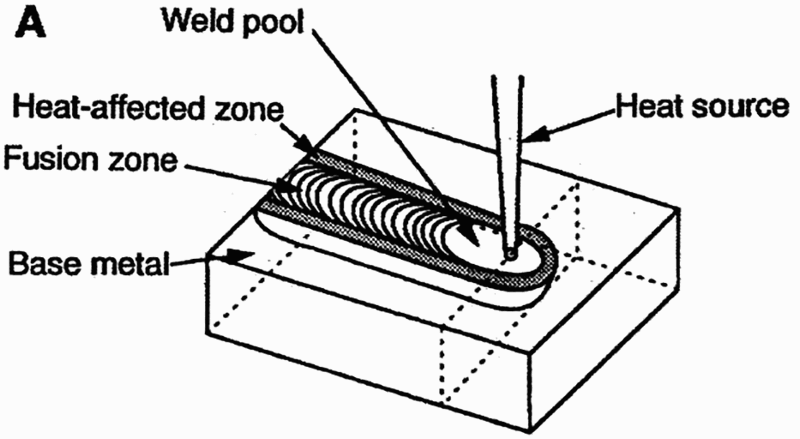
The alloys used to encapsulate RTGs and LWRHUs should all be weldable by means of conventional welding processes. The weldability of an alloy or metal is often influenced by a number of metallurgical and non-metallurgical factors such as composition, microstructure, process parameters and restraints.13, 14 The Ir alloys described in this paper are affected by all of these factors. For example, the weldability of Ir alloys is affected by alloy composition, FZ grain structure and process variables such as current and welding speed. A number of weldability tests have been developed to appropriately characterise the behaviour of material during welding and are discussed in the literature.13-16 However, most of the testing procedures require a significant amount of material; only a few weldability tests are available for thin sheets of material such as those used to fabricate RTGs and LWRHUs.
Considering the large tonnage of metals and alloys used in the form of thin sheets, it is essential to determine the weldability of materials in thin-sheet form. Also, the alloys described in this paper are very expensive and full-scale testing would be very difficult and cost-prohibitive. Thus, the initial weldability tests carried out in most of the alloy design and development programmes involve autogenous welding or melt run (also known as bead-on-plate weld) experiments in which thin sheets of alloy samples are used. Autogenous weld or melt-run tests give a quick assessment of the response of the materials to the weld thermal cycle. In particular, susceptibility to hot cracking can be determined. Some of the tests that are available for thin sheet of material are the Houlderment test, 17 the Lambert test 18 and the circular patch test. 10 The Sigmajig device and test procedure developed by Goodwin, 19 in which a transverse stress is applied to thin sheets before they are welded, have been used to measure and quantify the hot-cracking susceptibility of a number of alloys. 19 In fact, the Sigmajig procedure is the only test that quantifies the hot-cracking susceptibility of alloys and has found general acceptance and is being widely used.
Cracking during welding
Weldments encounter many types of cracking, some of them during welding and others during the post-weld period, including in service. They are solidification cracking, HAZ liquation cracking, reheat cracking (or strain-age cracking) and ductility-dip cracking. There are many tests to determine the susceptibility of the alloy to weld cracking.14-16 In Ir alloys, the most commonly observed cracking is hot cracking, which can manifest itself primarily as solidification cracking, less commonly as HAZ liquation cracking, or a combination of the two.
Solidification cracking
Many investigators have studied solidification cracking experimentally.20-23 The cracks form during the last stages of solidification. An alloy's susceptibility to solidification cracking is a function of both metallurgical factors and the level of strain produced at the end of solidification. The last liquid to solidify is distributed along the grain boundaries as a continuous film, and the strains due to thermal and solidification shrinkage cannot be accommodated. Thus, the boundaries separate to produce a crack. In terms of metallurgical causes, it is well established that the solidification temperature range as well as the amount and distribution of the terminal liquid are the primary factors that control the susceptibility of a metal to solidification cracking. 23
Extensive solute redistribution occurs during solidification 24 and the redistribution plays an important role in solidification cracking because it affects the solidification range and the amount of terminal liquid. Solidification cracking is favoured by factors that decrease the solid–solid contact area during the last stages of solidification. Two of the most important factors are the amount of low-melting segregates and grain size. Low-melting segregates can exist as a liquid film to temperatures well below the equilibrium solidus and reduce the grain boundary contact area to a minimum. Also, a coarser grain structure has less grain boundary contact area per unit volume for a given amount of non-equilibrium liquid. Hence coarse-grain weld FZs are more prone to solidification cracking.
HAZ liquation cracking
During welding, the BM adjacent to the FZ experiences a range of peak temperatures that lie between the liquidus and the effective (non-equilibrium) solidus temperatures of the alloy. 15 The microstructure within this region of the BM will undergo partial melting and is described as a ‘partially melted zone’. This can be further enhanced by segregation of low-melting elements to the grain boundaries. HAZ liquation cracking can occur in the partially melted zone when the liquid within the locally melted regions cannot withstand the applied stresses, and a crack forms along the grain boundaries. 15 The tendency for HAZ liquation cracking increases with high heat input.
HAZ liquation cracking can be associated with several types of localised melting, including melting at the grain boundary, constitutional liquation of secondary phases 13 and localised melting of eutectic constituents. Two basic mechanisms control grain boundary melting and HAZ liquation cracking 15 : (1) a segregation mechanism by which solute and tramp elements (low-melting constituents) segregate at the grain boundary and suppress the melting temperature of the grain boundaries and promote its melting and (2) a penetration mechanism by which local melting of precipitates, carbides and intermetallics at the grain boundary occurs and the liquid penetrates the grain boundaries and promotes its melting.
Grain structure development
To a large extent, the FZ microstructure is influenced by the BM grain structure and welding conditions.
24
The BM acts as an ideal substrate on which grains of solid can grow. Epitaxial growth proceeds from partially melted grains in the BM.
24
Nakagawa et al.,
25
Savage and Aaronson
26
and Samuel
27
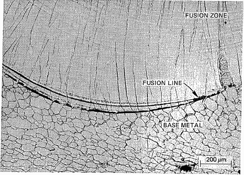
have used both microbeam X-ray and metallography techniques to confirm the epitaxial nature of weld metal solidification. Figure 6 shows the epitaxial growth in an Ir alloy weld. The average growth direction for grains to grow is normal to the solid/liquid interface and parallel to the heat-flow direction. During solidification of a weld pool, the growth of solid grains is initially influenced by crystallographic effects.
Epitaxial growth and columnar grains from the fusion line in an Ir alloy electron-beam weld (With permission from Welding Journal)
24
For cubic systems
 is the preferred easy growth direction for the solid to grow in a molten weld pool. Thus, the most favourable grains to grow are the ones whose heat-flow direction coincides with the crystallographic easy growth direction. A competitive growth process takes place among the various randomly oriented grains; the most favourably oriented grains grow faster and outgrow the less favourably oriented grains (see Fig. 6). This mode of preferred growth direction and growth selection process leads to a coarse-grain structure in the weld metal.
In the last decade or so, Rappaz et al. 28 and David et al. 29 analysed and demonstrated the competitive nature of growth of solids in the weld pool. As shown by their analyses of solidification in a polycrystalline material, the selection takes place among grains of different orientations, and the grains that survive are those with their easy growth directions optimally aligned. At any given direction, the grains that are oriented closest to the heat-flow direction are selected.
The shape of the weld pool also plays an important role in the development of the final grain structure. Fluid flow and heat transfer are two key factors that determine the size and shape of the weld pool. In the weld pool the metal undergoes vigorous circulatory motion driven by buoyancy, electromagnetic forces and variations in surface tension. Of these forces, the spatial variation of the surface tension due to temperature and composition gradients at the weld pool surface often provides the main driving force for the connective flow known as ‘the Marangoni flow’. Analytical models 30 and later numerical models31-34 were developed to predict the weld pool shape.
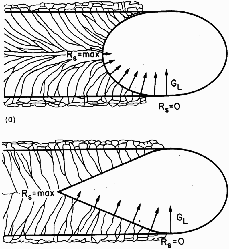
For welds made at low and moderate speeds, particularly in thin sheets of material, the weld pool as seen from the surface assumes an elliptical shape. As the welding speed increases, the weld pool shape changes from an elliptical to a teardrop shape (Fig. 7). For an elliptically shaped weld pool the direction of maximum thermal gradient changes continually from the fusion line to the weld centreline. As a result, no grain experiences preferred growth direction for an extended period of time. Therefore, many grains that form the fusion line survive to reach the weld centreline, and that results in a fine grain structure in the weld. These grains exhibit considerable curvature. For teardrop-shaped weld pool, there is almost an invariant direction of maximum thermal gradient at all points of the pool edge from the fusion boundary to the weld centreline. Generally, this results in the growth of a few favourably oriented grains at the expense of unfavourably oriented grains, which leads to a coarse columnar grain structure in the FZ. Using these principles, researchers have refined FZ grain structure in Ir and other alloys by oscillating the arc with magnetic poles.35-38 Arc oscillation during welding results in a complex pool shape in which growth direction changes continuously and causes remarkable distortion of the grain structure.35-38 Other techniques that have been used successfully to refine the FZ structure include arc pulsing,39, 40 electromagnetic stirring,41, 42 and mechanical and ultrasonic vibrations.
43
Schematic diagram showing variation of thermal gradient (GL) and growth rate (Rs) along the solidification front for differently shaped weld pools: a elliptical and b teardrop
24
Welding and weldability of Ir and Pt alloys
Ir alloys
Iridium is a scarce and expensive metal belonging to the Pt group. It is very dense and possesses many of the properties of other precious and refractory metals as well as other properties that make it unique. Ir and its alloys have high melting points, high-temperature strength and high-temperature corrosion resistance. Ir has very high elastic modulus, 44 critical resolved shear stress45, 46 and high hardening rate.46, 47 It is a face-centered cubic (fcc) metal and exhibits cleavage-type fracture during tensile testing. Ir alloys were chosen for RTG fuel encapsulation because of their properties and compatibility with the oxide fuel and the surrounding graphite. Ir alloys have also found a wide variety of other applications (e.g., catalysts, high-performance spark plugs, fountain pen nibs, crucibles). Recently, it has been shown that Ir alloys have potential for use as tool material for friction stir welding. Miyazawa et al. 48 investigated the performance of an Ir alloy (Ir-10% Re 1% Zr) and found it to be excellent for tools for friction stir welding of high-temperature materials because the alloy has excellent high-temperature oxidation resistance and shows hardly any wear.
However, Ir and its alloys also can have very poor ductility and a tendency for brittle fracture due to intrinsic grain boundary weakness. The problem was overcome by the addition of thorium
47
to the Ir-0.3% W, 50 ppm Al alloy. W was added to improve fabricability, and Th was added to strengthen the grain boundaries and to inhibit intergranular fracture during high-temperature, high-velocity impact testing. The role of Al is not very well understood; it is not present at the grain boundary but appears as a diffuse, wavy band within the grains. Th, whose concentration in the bulk material is only 30 ppm, segregates strongly to the grain boundaries, where its concentration is about 5–15 at.-%. The high level of Th in the grain boundaries can give rise to adverse effects such as grain boundary melting and hot cracking. Figure 8 shows an Ir–Th phase diagram.
49
The Ir-rich side of the phase diagram shows the presence of a eutectic reaction at 2080°C, leading to Ir + Ir5 − Th eutectic phases. This also indicates the possibility of formation of a low-melting eutectic due to segregation during the last stages of solidification that could cause hot-cracking problems. The solid solubility of Th in Ir is not known.
An Ir-Th phase diagram
49

Weldability of Ir alloys
Weldability of Ir alloys has been found to be a strong function of alloy composition, the microstructure of the FZ and the welding atmosphere. During the initial stages of alloy development, a series of Ir-0.3% W alloy containing up to 500 ppm Th with substantial high-temperature impact properties were developed at Oak Ridge National Laboratory (ORNL). 47 Based on extensive testing of high-temperature properties and corrosion and oxidation, two alloys were identified for further evaluation: DOP-14 (Ir-0.3% W, 200 ppm Th and 60 ppm Al) and DOP-26 (Ir-0.3% W, 60 ppm Th and 50 ppm Al).
Weldability screening of doped iridium alloys 36
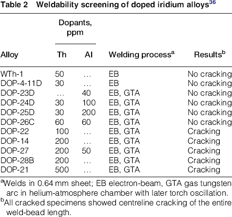
aWelds in 0.64 mm sheet; EB electron-beam, GTA gas tungsten arc in helium-atmosphere chamber with later torch oscillation.
bAll cracked specimens showed centreline cracking of the entire weld-bead length.
Weldability of DOP-14
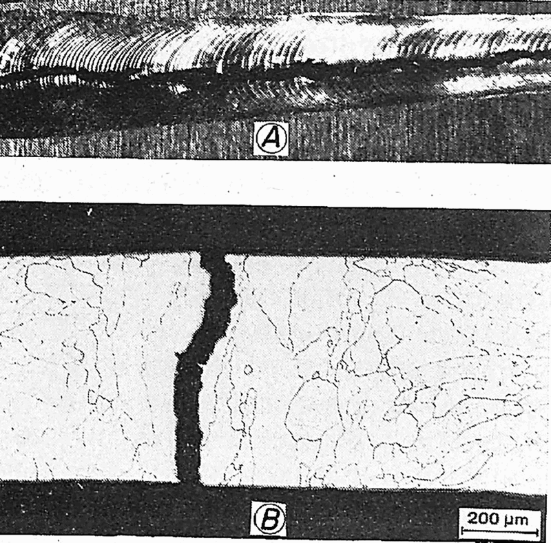
Weldability studies conducted on DOP-14 revealed that the alloy is prone to severe hot cracking during GTA welding.36, 50 Figure 9
a shows macrostructure of an autogenous bead-on-plate weld. Figure 9
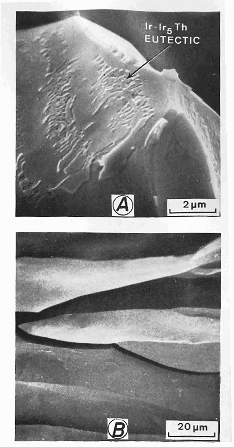
b shows the transverse microstructure the weld with a crack. The microstructure was found to be coarse; that is commonly observed in arc welds made on high-temperature alloys. Typically, one or two grains in these welds span the thickness of the sample. The crack always follows the centreline of the weld and is predominantly intergranular. Extensive scanning electron microscopy of the crack surface revealed the presence of an Ir + Ir5Th eutectic phase. Figure 10 shows the presence of a eutectic phase in the crack surface. Efforts to overcome the hot-cracking problem by refining the FZ grain structure using arc oscillation and pulsing the arc were not successful. However, successful welds without hot cracking were made by using a continuous wave, multikilowatt CO2 laser and EB welding.36, 50 Refinement in the FZ grain structure is attributable to the pool shape and to the epitaxial growth of the partially melted grains at the fusion line.
36
Macrostructure of an autogenous bead-on-plate weld. Welding speed: 2.5 mm s−1; a macrostructure and b microstructure of the weld (With permission from Welding Journal)
36
Scanning electron micrographs showing a eutectic patches on the surface of the fractured arc weld, and b absence of eutectic patches on the surface of a fractured laser weld by high-velocity impact testing
36
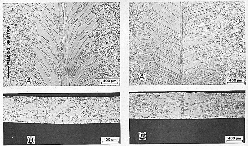
The successful application of the laser welding process to weld DOP-14 results from the highly concentrated heat source and the selection of weld process parameters to control weld heat input. Owing to the circular or elliptical nature of the weld pool during laser welding at a low to moderate welding speeds, most of the grains that grow epitaxially from the BM continue to grow normal to the solid–liquid interface; no single grain experiences a favoured growth for an extended period. Since the BM has a very fine grain structure without any grain growth in the HAZ, many grains from the fusion line survive to reach the centreline of the weld, leading to a refined grain structure in the FZ. Figure 11 shows the refined grain structure in laser welds made at welding speeds of 12.5 and 25.0 mm s−1. This refinement in grain structure improves the hot-cracking resistance of the alloy.
Fusion zone microstructure of a laser weld. Left: welding speed 12.5 mm s−1: a top surface and b transverse section. Right: welding speed 25.0 mm s−1: a top surface and b transverse section (With permission from Welding Journal)
36
Weldability of DOP-26
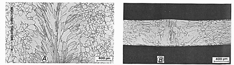
DOP-26 (Ir-0.3% W, 60 ppm Th and 60 ppm Al) can be successfully welded by both GTA, EB and laser welding processes. Although the weldability of DOP-26 is much superior to that of DOP-14, the coarse unfavourable FZ structure in early DOP-26 GTA welds could severely reduce ductility and strength. In addition, the hot-cracking sensitivity and the quality of the DOP-26 alloy welds were found to be a strong function of Th content and the composition of the welding atmosphere. Therefore, it is critical to ensure that the FZ grain structure is fine enough to provide the required weld ductility as well as resistance to hot cracking.
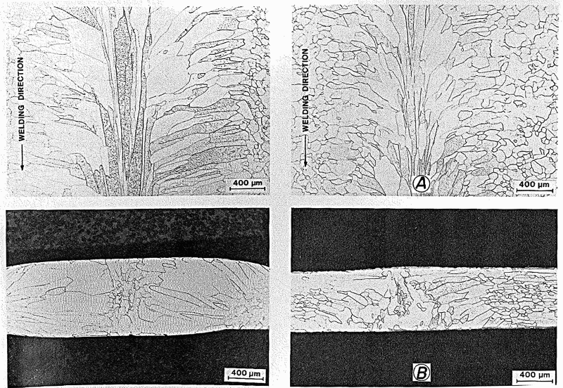
Refinement in the FZ grain structure of DOP-26 alloy welds has been achieved by using arc oscillations during GTA welding or by using the laser welding process. Figure 12
a and b, respectively, show microstructures of arc welds made without and with arc oscillations. Figure 13 shows the microstructure produced by the laser welding process. A magnetic oscillator was used to introduce arc oscillations during welding. Arc oscillations both in the direction of welding (longitudinal) and normal to the welding direction (transverse) were evaluated at a constant amplitude and dwell time. Of the two directions, transverse oscillations at a frequency of 375 cycles min−1 were found to be effective.
51
A number of factors may contribute to the refinement in the DOP-26 grain structure due to arc oscillations. When arc oscillation is employed, both the shape of the weld pool and the instantaneous growth rate at the trailing edge of the weld pool can be made to vary with time. Also, the direction and magnitude of the temperature gradients may be altered periodically as the heat source is oscillated, leading to variations in the growth direction and weld pool solidification conditions. The refinement in the FZ grain structure of the alloy DOP-26 laser welds was mainly due to the circular or elliptical pool shape obtained during laser welding at low or moderate welding speeds.
Fusion zone microstructures of arc welds, welding speed 12.5 mm s−1. Left: without arc oscillations, a top surface and b transverse section. Right: with oscillations, a top surface and b transverse section (With permission from Welding Journal)
36
Fusion zone microstructure of a laser weld, welding speed 8.3 mm s−1: a top surface and b transverse section (With permission from Welding Journal)
36
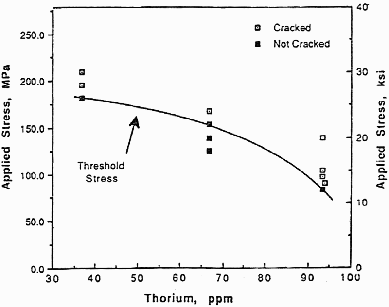
The Sigmajig test by Goodwin was used to evaluate the effect of thorium in the alloy composition and the composition of the atmosphere on the weldability of DOP-26.
19
The hot-cracking behaviour for a series of sheet materials alloyed with varying amounts of Th is shown in Fig. 14 for varying applied threshold stress. The threshold stress decreases from 170 MPa at the 37 ppm Th level to half that value at 94 ppm thorium. Although the resistance to cracking decreases substantially at the higher Th level, the material has some degree of resistance to hot cracking at the highest Th level in the alloy investigated. This decrease in the threshold stress at higher levels of Th, which can cause cracking, can be attributed to increased levels of low-melting eutectic available to wet the grain boundaries. The results were confirmed by David et al.
29
DOP-26 containing 2000–4000 ppm W, 30–90 ppm Th and 20–80 ppm Al used for current space missions contains optimal amounts of the alloying elements to give good grain boundary strength and hot-cracking resistance.
Materials produced with controlled variations in Th content from identical melt stock show decreased threshold cracking stress with increased Th content
52
Th that is added to Ir alloys segregates to the grain boundary and strengthens it. The level of Th at the grain boundary is significantly elevated versus the bulk alloy composition.
7
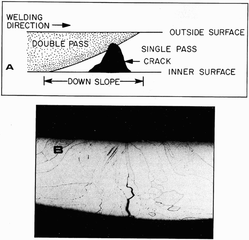
This Th enrichment at the grain boundary could cause melting and the formation of low-melting eutectic and weakening of the grain boundary. In production welds of alloy DOP-26, the significant problem was the formation of small underbead crack under the arc taper tying an overlapping weld to a previous weld.10, 53 The underbead cracking phenomenon is shown schematically in Fig. 15. The crack was very irregular and did not extend to the surface through the weld thickness of the capsule. This is attributed to HAZ liquation cracking in the primary weld.
Typical underbead weld cracks in alloy DOP-26: a schematic of longitudinal section showing crack location and b transverse weld microstructure with the crack (With permission from Welding Journal)
10
The effect of welding atmosphere on the hot-cracking sensitivity of the alloy DOP-26 was evaluated by conducting Sigmajig tests in a controlled atmosphere containing oxygen and moisture. 52 Neither were found to have an effect on the hot-cracking behaviour of the alloy DOP-26. However, the presence of oxygen had a major effect on the weld geometry. Welds made with high oxygen content were found to have much wider weld bead. This is mainly due to the nature of fluid flow within the weld pool. Impurities in the weld metal such as oxygen and sulphur are often active at the surface in that they alter the surface tension and the temperature coefficient of surface tension of the liquid metal (dγ/dT). Depending on whether dγ/dT is negative or positive, the direction of convective flow could be inward with the hot liquid flowing deeply into the centre of the weld pool and increasing the depth of the weld or outward with the hot liquid flowing toward the edge of the weld pool, making the weld wider.54-56 It appears that the effect of oxygen on the surface of the weld pool and on the temperature coefficient for surface tension for Ir and its alloys is negative and that the hot liquid from the centre of the pool flows outward, increasing the width of the weld. However, specimens used for weldability tests were in thin-sheet forms; thus the heat-flow conditions may also give a wider pool shape.
Welds of Ir alloy cladding over fuel pellets were performed by automated GTA welding. 57 The weld was performed in an atmosphere of helium using He-25% Ar as a shielding gas. 57 Initial difficulties with weld cracking in the underbead region of the weld taper zone at the end of the weld caused yields to be reduced to unacceptable levels. The use of a four-pole magnetic oscillator was found to substantially reduce the incidence of weld cracking. 57 These methods were used satisfactorily during the 1980s to produce hardware for the Galileo and Ulysses spacecraft.
Process modifications
Better results for crack-free welds were achieved because of changes made to the Ir alloy production process and to welding practices. 53 A number of improvements in both materials and welding methods were made for RTGs used in the Cassini spacecraft, which was launched in 1997. The production methods for the Ir alloy for the fuelled clads were improved to increase yield and to eliminate potential sources of defects in the material. 58 The effects of the processing changes on weldability were evaluated using a laboratory test in which repeated short weld passes were made over an existing weld bead to promote cracking. Fluorescent dye penetrant inspection was used to obtain the total lengths of the cracks. The results of the test showed improved weldability and reduced susceptibility to cracking for the new process material. 57
Changes in the welding process and in the weld setup were also made to improve process yields when welding Ir alloy components. These changes included separate assembly of Ir cups into snap-in chucks, a precision weld start location, and synchronous rotation of upper and lower chucks under a controlled load, which permitted elimination of the tack-welding process that had been used previously. 59 The welding process yield for 319 capsules produced for Cassini was 97.8%. The total yield of welded capsules for Cassini improved to 88.7% from the 72.7% yield for the earlier production runs. 60
Mechanical properties of Ir welds
Liu and David characterised the mechanical behaviour of DOP-26 alloy as a function of weld-bead width, microstructure, post-weld heat treatment (PWHT) and temperature. 61 The mechanical properties of Ir alloy welds depend strongly on the grain structure. 61 The development of an unfavourable coarse-grain structure in GTA welds may have an adverse effect on the properties of the welded joints (e.g., severely reduced ductility). Thus, weld parameters were selected judiciously to counter heat input and solidification rates. 62 DOP-26 was welded by GTA process (melt runs), and the mechanical properties were characterised by using tensile and impact testing from 650 to 1150°C. The results were compared with the BM properties. 61 The FZ grain structure was controlled by arc oscillation heat input and PWHT. Emphasis was placed on the correlation of the mechanical properties of welds with one or two grains across the weld in the welded structure, heat treatment and fracture path. The samples underwent PWHT in the temperature range of 1290–1800°C. Tensile tests were carried out on an Instron machine, and tensile impact tests were conducted in an impact chamber with a gas gun to accelerate the samples to a velocity of 61 m s−1.
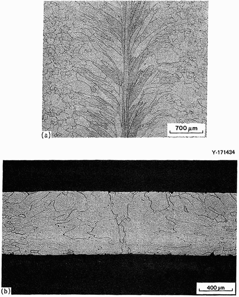
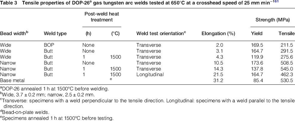
Microscopic examination of the welds revealed that the FZ grain structure of DOP-26 GTA welds depends strongly on heat input, pool shape and bead width. Grains in the FZ were fine, and most exhibited considerable curvature. Figure 16 shows the microstructure typical of a weld with a wide bead. Figure 17 shows microstructures of a weld with a narrow bead. Table 3 summarises the tensile properties of DOP-26. The BM shows a tensile elongation exceeding 30%. The welded specimens show higher yield strengths but much lower ductilities. Tensile ductility depends on the surface bead width. Tensile elongations are significantly higher for the narrow beads than for the wider beads.
Fusion zone microstructure of a DOP-26 weld with a wide-bead (3.7 mm) width; no PWHT: a top surface; b transverse section
61
Fusion zone microstructure of a DOP-26 weld with a narrow-bead width (2.5 mm); no post-weld heat treatment: a top surface and b transverse section.
61
Tensile properties of DOP-26a gas tungsten arc welds tested at 650°C at a crosshead speed of 25 mm min−161
aDOP-26 annealed 1 h at 1500°C before welding. bWide, 3.7 ± 0.2 mm; narrow, 2.5 ± 0.2 mm. cTransverse: specimens with a weld perpendicular to the tensile direction. Longitudinal: specimens with a weld parallel to the tensile direction. dBead-on-plate welds. eSpecimens annealed 1 h at 1500°C before testing.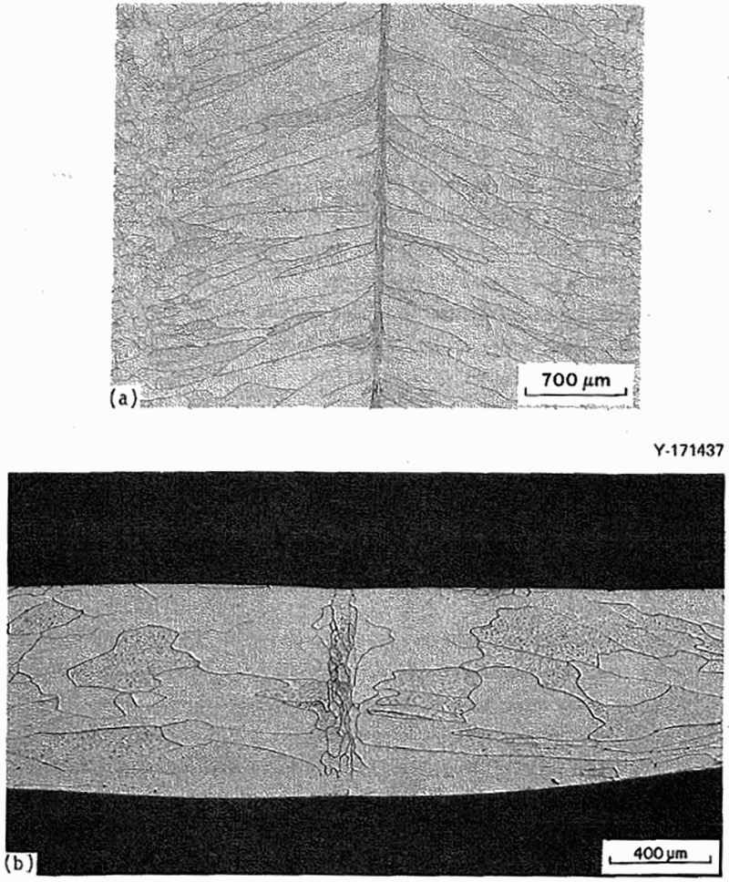
The fracture mode of the BM is compared with that of a weld with a narrow bead in Fig. 18. The welded specimen b shows grain boundary fracture and has a very brittle appearance whereas the BM a fractures across the grain. Table 4 shows impact properties of a DOP-26 GTA weld.
Scanning electron microscopic fractographs of DOP-26 specimens tensile-fractured at 650°C at a crosshead speed of 25 mm min−1: a base metal and b transverse weld with the narrow-bead width (post-weld heat treatment: 1 h at 1500°C)
61
Effect of weld-bead width and post-weld heat treatment on impact properties of DOP-26 specimensa with a transverse weld (impact velocity: 61 m s−1)
61
aDOP-26 specimens annealed 1 h at 1500°C before welding. bWide, 3.7 ± 0.2 mm; narrow, 2.5 ± 0.2 mm. cHeat-treated 1 h at 1500°C after welding. dWithout weld.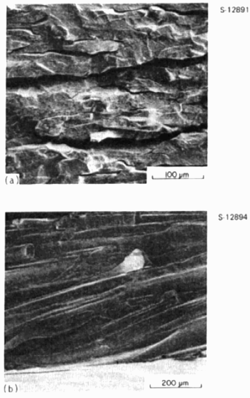
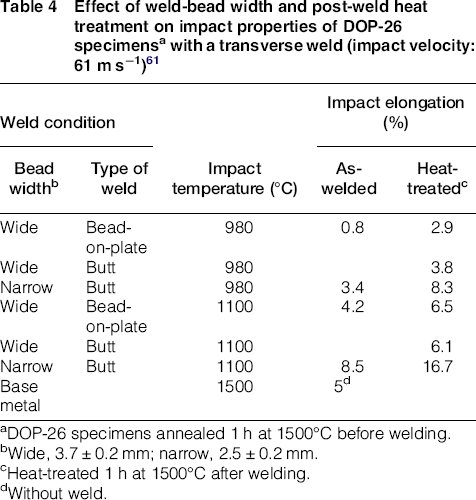
The narrow weld was found to have an impact ductility that was much better than the wider weld. In fact, the impact ductility at 990 and 1100°C more than doubled as the surface bead width was reduced from 3.75 to 2.5 mm, respectively.
Weldability of Pt alloys
Pt alloys have high melting points, thermal stability and thermal shock resistance as well as corrosion and oxidation resistance, and good electrical and thermal conductivity. 8 These properties make them very attractive for use in catalytic chemistry, space technologies, medical applications and the glass industry. 8 Pure Pt has low mechanical strength. Alloying it with Rh improves its strength properties a great deal. Solid-solution strengthening improves ductility at high temperatures, and the alloys are weldable. Mechanical strength and grain-growth control can be achieved for Pt and its alloys at temperatures up to 1600°C through oxide-dispersion-strengthening (ODS) However, ODS Pt alloys are not weldable because of the coagulation of dispersoids and removal from the FZ, resulting in ductility reduction. 63 To overcome this problem, a Pt dispersion-hardened material (DPH) was developed by W. C. Heraeus in collaboration with the University of Applied Sciences, Jena. 63 Internal oxidation principles were used to produce the new Pt DPH material. Oxidising elements such as Zr, Y and Cs were added to Pt melts and cast. The cast alloy was rolled into sheets and given an annealing treatment in an oxidising atmosphere, which led to internal oxidation of the alloy. 63 With the introduction of Pt DPH alloy, the disadvantages of cracking and reduction in strength were eliminated. The material can be easily welded using the GTA process with or without filler metal. The strength of the weld metal was not affected significantly. If needed, the welds can be subjected to an annealing treatment.
Pt alloys are used to encapsulate Light Weight Radioisotope Heater Units. The Pt-30 wt-% Rh alloy is the material of choice for Light Weight Radioisotope Heater Unit fuel encapsulation. Pure Pt and solid-solution-strengthened alloys are weldable using GTA, EB, and laser welding processes. GTA is recommended for ODS Pt alloys.
Prognosis
Ir and Pt alloys will continue to be used for fuel encapsulation in RTGs providing instrument power for deep space missions. Also, welding will continue to be the joining technology for the fuel encapsulation process. However, there is ample room for material and/or process modifications to improve weldability and impact properties. Beyond GTA welding, other high-energy processes, such as laser and electron-beam welding processes have the potential to produce parts with improved weld-cracking resistance and the added advantage of producing fine grain structured FZs and thereby avoid hot-cracking problems.
Footnotes
Acknowledgments
The authors would like to acknowledge Walter Koncinski and Shirin Badlani for the time and effort in helping to prepare the manuscript. Also, they would like to acknowledge Jian Chen for all his help. Finally, the authors would like to thank George Ulrich, of Oak Ridge National Laboratory, and Professor H. K. D. H. Bhadeshia, of Cambridge University, UK, for reviewing the paper and for their valuable comments.
1
All the alloy compositions are given in weight percent for major elements and in weight parts per million for minor elements.