
Abstract
Transformation-induced plasticity (TRIP) steel resistance spot welds are delicate to low-energy interfacial failure via crack propagation through martensitic fusion zone during cross-tension (CT) loading. This paper addresses the effect of three different types of in situ postweld heat treatment (PWHT) on the mechanical properties of TRIP steel resistance spot welds. Depending on the post weld second pulse current level, three different strengthening mechanisms were found including (i) martensite tempering with reduced hardness, (ii) refining of martensite packets with improved toughness and (iii) nugget re-melting/enlargement combined with possible reduction of grain boundary impurity segregation. All designed in situ PWHTs were enabled to promote pullout failure mode with improved load-bearing capacity and energy absorption capability during CT loading.
Introduction
The use of advanced high strength steels (AHSS) is a key strategy to address the conflicting demands on the automotive industry to simultaneously improve crash safety and fuel economy [1]. As resistance spot welding (RSW) is crucial manufacturing technology in sheet metal joining, the weldability of AHSS is one of the key factors governing their widespread application in the automotive industry. The well-designed microstructure of the base metal (BM) is destroyed in the fusion zone (FZ) and heat affected zone (HAZ) [2-8] affecting the mechanical performance of the resistance spot welds. As the weld failure during a crash is a critical issue for crashworthiness, stiffness and NVH (Noise, Vibration and Harshness) performance of the vehicle [9-11], there is need to improve load-bearing capacity and energy absorption capability of the resistance spot welds.
Transformation-induced plasticity (TRIP) steels show a unique microstructure of ferrite, bainite/martensite and retained austenite in which the latter plays the role for the TRIP effect (i.e. transformation of austenite to martensite upon loading) providing resistance to necking with increased work hardening rate and improved energy absorption [12]. Therefore, they are promising materials for automotive application. However, they exhibits some weldability issues including high susceptibility to interfacial failure (IF) mode (i.e. crack propagation through FZ) with reduced strength and energy absorption during cross-tension (CT) loading condition [13-18]. Therefore, their use in automotive applications is limited by their low weldability. This calls for design an appropriate approach to improve the weldability of TRIP steels.
It has been identified that the high susceptibility of TRIP steel to IF during CT loading is due to formation of hard and brittle martensite in the FZ [2]. The fracture toughness of the FZ in the steel resistance spot welds can be improved by modification of the as-welded microstructure of FZ via in situ postweld heat treatment (PWHT). One of the proven methods for alleviating the problem of high sensitivity to IF of the AHSS welds is the use of in-process quench and tempering of the weld [19]. The aim of this technique is to reduce the FZ and HAZ hardness via martensite tempering [19-21]. To perform a proper quench and tempering treatment on the weldment, the cooling time (time between the first melting/solidification pulse and the second current pulse) should be selected such that the weldment is cooled to a temperature slightly below the martensite finish temperature (Mf), before being heated for tempering. Then, tempering time and tempering current should be adjusted such that the martensite tempering process occurred in sufficient extent to reduce FZ hardness [2, 19]. It is shown that by using an optimised in situ tempering a preferred pullout mode can be achieved [19, 22-24]. However, Uijl et al. [25] stated that if the reason for IF mode is not only the high FZ hardness but also the decreased coherency between the columnar grains in FZ due to S and P segregation, the in process tempering is not sufficient to obtain full PF mode during CT testing. They suggested that applying a PWHT to re-melt the edge of the weld nugget can destroy the disadvantageous columnar grains and dendritic structure and reduce the segregation level of S and P which in turn improved the failure mode. Sawanishi et al. [26] also showed that pulsed current can improve the P segregation at the weld nugget. Baltazar Hernandez et al. [18] showed that it is possible to create equiaxed grains at the weld nugget edge by applying a second pulse current. Wakabayashi et al. [27] showed that application a prolonged second pulse can increase the grain size in the HAZ thereby promoting the martensite auto-tempering which in turn can improve the mechanical properties of the welds. In addition to PWHT, the toughness of the FZ can be improved by lowering its hardness by introducing a low carbon steel shim insert between steels to be welded [28] and dissimilar welding of high alloyed steel to lean alloyed steels [29].
This paper aims at investigating the effect of in situ PWHT on the mechanical properties of TRIP700 resistance spot welded under CT test. Based on the work carried out by Baltazar Hernandez et al. [18], three different in situ PWHTs were designed to modify the FZ microstructure. Unlike, Hernandez's work in which the mechanical properties of the welds were evaluated during tensile-shear test, in the present work, the mechanical properties were evaluated under CT loading, as it is more sensitive to the presence of brittle microstructure at the joint interface compared to the tensile-shear test [2, 29]. Then, the strengthening mechanisms of the spot welds after PWHT are discussed in the light of FZ microstructure evolution.
Materials and method
Chemical composition and mechanical properties of the investigated TRIP steel.
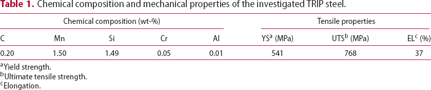
aYield strength.
bUltimate tensile strength.
cElongation.
RSW was performed using a PLC controlled, 120 kVA AC pedestal type RSW machine. Welding was conducted using a 45-deg truncated cone RWMA Class 2 electrode with 8-mm face diameter. Two different schedules were performed in this work:
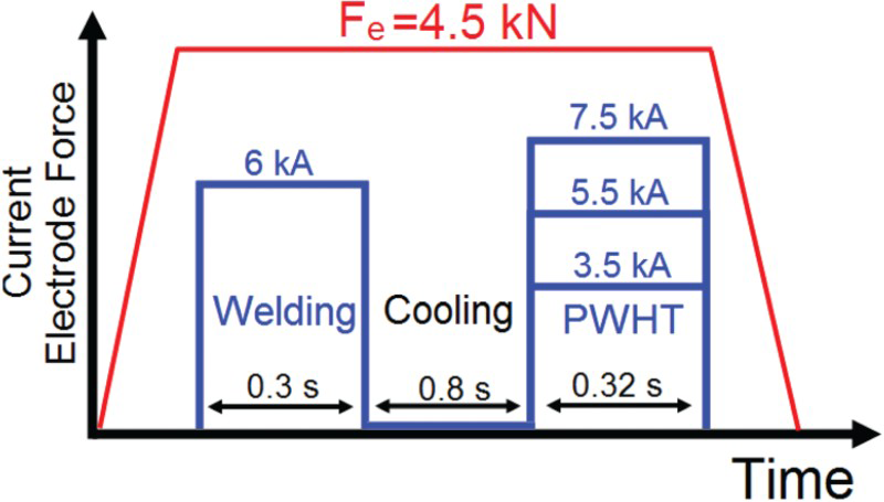
Welding: The aim of this procedure was to produce a weld with a target FZ size of 4t0.5 [2, 8] (i.e. conventional recommendation sizing criterion for spot welds). PWHT: After conventional single pulse welding, a second pulse current was applied to the weld area aiming at improvement of the weld properties. Three different postweld pulse currents were performed (ca. 3.5, 5.5 and 7.5 kA). Figure 1 shows the schematic of welding/postwelding schedules. Welding and PWHT schedule used in this study.
The quasi-static CT test was carried out on 5 cm ×15 cm samples, according to ANSI/AWS/SAE/D8.9-97 standard [30]. The CT tests were performed at a crosshead speed of 10 mm min−1. Peak load (measured as the peak point in the load–displacement curve) and failure energy (measured as the area under the load–displacement curve up to the peak load) were extracted from the load–displacement curve. Failure modes of spot welds were determined by observing the weld fracture surfaces. The fracture surface of the broken sample was studied using scanning electron microscopy (SEM).
Weld microstructures and macrostructures were examined under optical microscopy and SEM. Metallographic samples were etched by Nital reagent. The FZ size was measured on the metallographic cross-section. Microhardness test was used to assess the hardness values of the weldment. An applied load of 100 g and a time of 15 s were used.
Results and discussion
Microstructure-property relationship in as-welded condition
Figure 2(a) shows the overall macrostructure of the TRIP steel resistance spot weld. Figure 2(b) demonstrates the FZ microstructure indicating predominately martensitic structure with the average hardness of 425 HV which is well above the average hardness of the BM (ca. 228 HV). Martensite formation in the FZ is attributed to the high cooling rate of RSW and high hardenability of TRIP steel [31].
Metallurgical structure of as-welded TRIP steel resistance spot welds and its consequent on the fracture mode in CT loading: (a) weld overall macrostructure: The weldment consisted of three distinct zones, namely, FZ, HAZ and BM. The relative materials properties of these zones and the behaviour of weld natural notch at sheet/sheet interface during loading are keys for determining the weld failure characteristics. (b) Martensitic FZ microstructure, (c) IF mode (d) fracture surface morphology.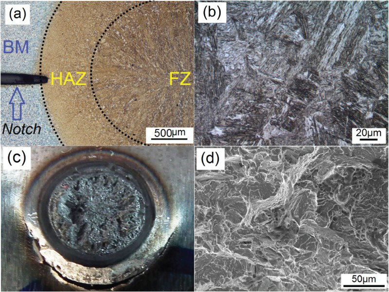
Mechanical testing of as-welded spot weld using CT test, which induces mode I loading at the joint notch at sheet/sheet interface [2], showed that the welds failed via crack propagation into the FZ, Figure 2(c), (i.e. IF mode). Figure 2(d) shows the fracture surface at the weld nugget edge indicating a semi-cleavage fracture. Owing to the presence of hard and brittle martensitic structure, loading at mode I (i.e. opening mode) led to semi-cleavage fracture of the FZ confirming a low-energy brittle failure. Therefore, it can be concluded that the IF of the TRIP steel welds under CT is controlled by fracture toughness of the FZ [2, 32, 33]. Hence, the full IF of TRIP steel spot weld with FZ size larger than 4t0.5 can be attributed to the low fracture toughness of the FZ which in turn is due to high hardenability (i.e. high carbon equivalent) of the investigated steels. Owing to importance of carbon equivalent for assessment of susceptibility of spot welds to IF mode during CT or peel test some special carbon equivalent have been developed [2]. For example, if CE = C + Si/30 + Mn/20 + 2P + 4S is above a critical limit (i.e. 0.24), the welds are highly susceptible to IF [34]. According to Table 1, the CE for the investigated steel is 0.33 which is well above the critical value. This indicates that the investigated steel exhibited high susceptibility to crack propagation thorough FZ.
There are two approaches to obtain pullout failure (PF) mode and improve mechanical properties including: (i) changing the weld physical attributes (i.e. increasing FZ size) and (ii) improving the FZ fracture toughness. In this work, three different PWHTs are designed aiming at improving mechanical properties of the weld during CT loading.
Effect of PWHT on weld metallurgical/mechanical characteristics
PWHT was performed by applying second current pulse after the first melting and re-solidification pulse. Three postweld current (3.5, 5.5 and 7.5 kA) for a duration of 0.32 s were applied. Figure 3(a) shows the effect of PWHT on the load–displacement characteristics of the welds. Figure 3(b,c) shows mechanical properties of the welds after PWHT indicating that both peak load and energy absorption were improved upon applying PWHT. The peak load and failure energy was improved by about 60 and 50%, respectively, at the best condition. Examination of the fracture surface (Figure 4) showed that all welds produced using PWHT failed in PF mode. The improvement of the mechanical properties after PWHT is linked to the IF to PF failure mode transition which is corresponds to failure path alteration from hard and brittle martensitic FZ to the softer HAZ/BM. To explain the reasons behind the improvement of the failure mode and mechanical performance of the welds after PWHT, the variation of physical/metallurgical weld attributes should be investigated:
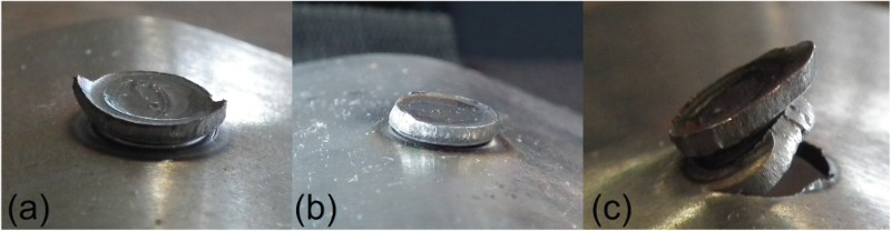
Effect of PWHT on CT mechanical properties of TRIP steel resistance spot welds (a) Load–displacement curves (b) peak load, (c) failure energy. (A: as-welded, B: PWHT at 3.5 kA, C: PWHT at 5.5 kA and D: PWHT at 7.5 kA). Failure mode of TRIP steel RSW after PWHT using a second pulse current of (a) 3.5 kA, (b) 5.5 kA and (c) 7.5 kA. All PWHT cycles were successful in changing the fracture mode from IF mode to pullout mode.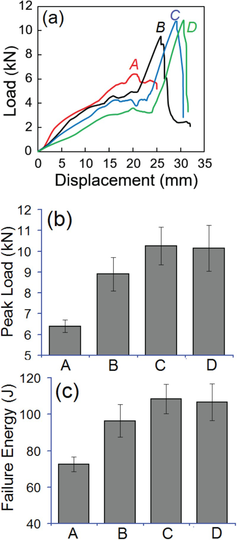
Effect of PWHT on the FZ size
Figure 5 shows the effect of PWHT on the FZ size. As can be seen, FZ size after PWHT at current of 3.5 and 5.5 kA are essentially same compared with that of in single pulse welding. This indicates that improving weld mechanical properties in these conditions can be related to the metallurgical factors. However, PWHT using second pulse current of 7.5 kA exhibited larger FZ indicating that the second pulse led to melting of the first nugget periphery and extension the weld nugget. Considering weld nugget enlargement during PWHT at heating current of 7.5 kA, it can be concluded that the peak temperature during PWHT was above the BM melting temperature.
Effect of PWHT on FZ size (A: as-welded, B: PWHT at 3.5 kA, C: PWHT at 5.5 kA and D: PWHT at 7.5 kA).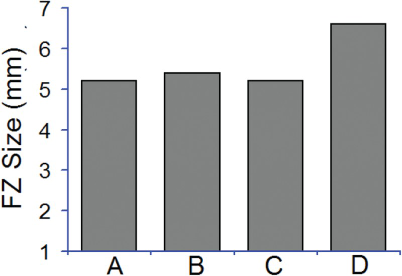
Effect of PWHT on the FZ microstructure/hardness
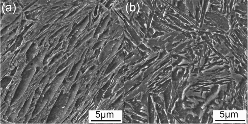
Figure 6 shows the effect of PWHT on the average hardness of the FZ. As can be seen, the FZ hardness was reduced by about 60 HV after applying a second pulse current of 3.5 kA. This suggests that the PWHT at this condition promotes the martensite tempering). Figure 7 shows the effect of PWHT using 3.5 kA second pulse current on the as-welded FZ microstructure. As can be seen, the predominantly lath martensite structure of the FZ in the as-welded condition (Figure 7(a)) was decomposed to tempered martensite (Figure 7(b)) after in situ PWHT using 3.5 kA second pulse current.
Effect of PWHT on the average FZ hardness (A: as-welded, B: PWHT at 3.5 kA, C: PWHT at 5.5 kA and D: PWHT at 7.5 kA). Converting martensitic FZ in as-welded condition (a) to tempered-martensite microstructure after in situ PWHT using 3.5 kA second pulse current (b). This phase transformation improves ductility of the FZ, resulting in improved strength with PF mode.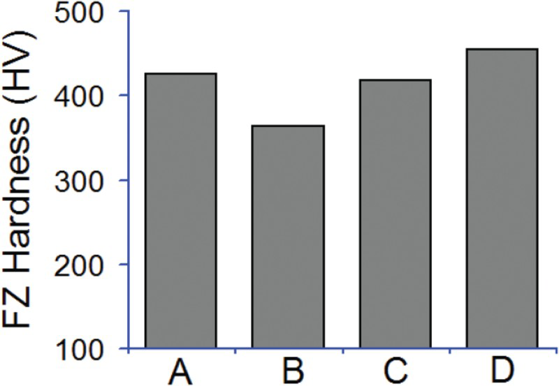
It should be noted that further studies are needed to better characterise the tempered-martensite structure via transmission electron microscopy.
No hardness reduction was observed after PWHT using 5.5 kA second pulse current. However, the grain structure of the FZ was changed after PWHT at this condition. Formation of columnar grain structure is predominant in the as-welded FZ (Figure 2(a)). However, the columnar grain structure was interrupted when PWHT at 5.5 kA. According to Figure 8(a), by moving from fusion line to the sheet/sheet interface, there is a transition from columnar grain zone (CGZ) to equiaxed grain zone (EGZ). The formation of EGZ in the FZ centre of postweld heat treated sample using second pulse current of 5.5 kA, suggests that the refining of columnar primary austenite grains occurred during rapid re-austenisation of the weld nugget during PWHT. A similar phenomenon is reported by Hernandez et al. when PWHT of TRIP steels [18]. According to Figure 8(b,c), the FZ microstructure in CGZ and EGZ is predominantly martensitic that explains why no hardness reduction was observed in PWHT-5.5 compared to the as-welded sample. Figure 8(b–d) compares the martensite packet size, as the effective grain size in the lath martensite [35], before and after PWHT at 5.5 kA second pulse current. As can be seen, the martensite packet sizes of the as-welded sample and of the CGZ in the PWHT-5.5 sample are comparable. However, the martensite packets are significantly refined in the centre of the FZ after PWHT using 5.5 kA compared to the as-welded condition. This is due to martensite-austenite reversion process through rapid heating and quenching during in situ PWHT. Upon rapid heating, the density of austenite nuclei is significantly increased leading to refining the primary austenite grains which in turn resulted in finer martensite packets [36].
Martensite refining in the weld nugget after in situ PWHT using 5.5 kA compared to the as-welded condition: (a) transition of columnar to equiaxed grain structure by moving form fusion line to nugget centre in PWHT5.5 sample (b) martensite structure at CGZ, (c) martensite structure at EGZ, (d) martensite structure in as-welded condition. Compared to the as-welded condition, the martensite packets are refined in the weld nugget centre after PWHT using 5.5 kA second pulse current.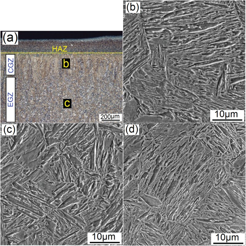
PWHT using 7.5 kA second pulse current resulted in no hardness reduction compared to the as-weld condition. Metallographic examinations showed that the FZ consisted of columnar austenite grains (Figure 9(a)) with predominantly martensitic microstructure. No martensite packet refining was observed in FZ after PWHT at 7.5 kA second pulse current in respect to the as-weld condition.
FZ microstructure of TRIP steel RSW after PWHT using a second pulse current of 7.5 kA: (a) optical microstructure showing columnar primary austenite grains consisting martensite, (b) SEM micrograph showing block structure of martensite formed in the FZ.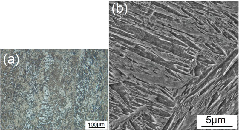
Strengthening mechanisms due to PWHT
The failure mode of spot welds during CT loading is competition between crack propagation under mode I loading due to imposed tensile stress at the notch of sheet/sheet interface (i.e. IF mode) and shear plastic deformation in the HAZ or BM (i.e. PF mode) [2]. Based on this competition, the tendency to fail in the pullout mode in CT loading is proportional to the ratio of the fracture toughness of the FZ to the hardness of the BM/HAZ. Considering the variations of physical/metallurgical attributes of the welding during PWHT, three distinct mechanisms can explain the achieved improvements in mechanical performance:
Mechanism I: martensite tempering
It is well known that martensite tempering improves fracture toughness of the steels [37]. Tempering of martensitic weld nugget can be achieved using a low temperature PWHT when the peak temperature experienced during PWHT is below A1. This mechanism was observed in weld post-heated at 3.5 kA second pulse current, as it is evidenced by reduced hardness value in the weld nugget (Figure 6) and formation a decomposed tempered structure in the FZ (Figure 7).
Mechanism II: martensite refining
The nugget in weld post-heated at 5.5 kA did not exhibit hardness reduction compared with the single pulse sample and a full martensitic structure was retained in the weld nugget after PWHT. Therefore, the improved mechanical properties of this sample cannot be attributed to the martensite tempering. However, it can be related to martensite refining in the FZ centre (Figure 8). It is well known that columnar large grains provide a low fracture toughness and hence easy crack propagation path. The destruction of columnar grain structure and formation of semi-equiaxed structure with refined martensite packets can impede the crack propagation through FZ resulting in PF mode with improve mechanical properties. This mechanism can be activated at medium temperature PWHT when the peak temperature experienced during PWHT is between A3 and melting temperature. It is of note that successive martensite-austenite reversion heat treatment technique has been previously applied to produce fine grained martensitic steels with improved fracture toughness [36, 38, 39].
Mechanism III: Weld nugget enlargement and possible segregation modification
The nugget in weld post-heated at 7.5 kA showed neither hardness reduction nor martensite packet refining. Therefore, the improvement of mechanical properties in PWHT-7.5 sample primarily can be attributed to weld nugget enlargement (Figure 5) associated with this high temperature PWHT. The larger weld nugget size provides larger weld bonding area which in turns promotes PF mode and improves mechanical properties in terms of both peak load and energy absorption.
It is interesting to note that the segregation of impurities (e.g. S and P) in the weld nugget can reduce nugget fracture toughness and promotes IF mode [2]. It has been reported that the re-melting of weld nugget edge during PWHT can reduce the S and P segregation and improve failure characteristics of the spot welds [23].This phenomena can also partly explain the observed improvement in mechanical properties after PWHT at 7.5 kA, in addition to weld nugget enlargement. This mechanism needs further investigations. Therefore, the strengthening achieved in this condition can be related to the changes in both physical and metallurgical attributes of the weld.
It is of note that the success of the proposed PWHTs is highly depended on precise controlling the temperature distribution during PWHT which in turns is influenced by several factors including quench time, PWHT time and current. This calls for optimisation of PWHT parameters to achieve best weld mechanical performance.
Conclusions
RSW of TRIP steels with conventional welding practices may not be the preferred approach to realise the full advantages of TRIP effect in transport vehicles. The possibility of in situ controlling of thermal cycle during RSW provides significant opportunity for modification of weld microstructure and hence improving failure mode transition behaviour and enhancing the mechanical properties. It is demonstrated that introducing a second pulse currents after first melting/solidification pulse which are able to (i) temper the as-weld martensite or (ii) refine the martensite packets can enhance the fracture toughness of the FZ impeding the crack propagation through FZ that enables producing PF with improved peak load and energy absorption during CT loading, where mode I loading is imposed to the sheet/sheet interface notch. Moreover, applying a second pulse current puissant to re-melting and enlarging the weld nugget can improve the mechanical properties due to modification of weld geometry as well as possible grain boundary impurity segregation reduction. The latter effect needs further investigation. It should be noted that the success of these techniques is highly depended on the precise controlling of temperature distribution during PWHT which is possible by application of sophisticated numerical modelling.
Footnotes
Disclosure statement
No potential conflict of interest was reported by the authors.