
Abstract
The paper critically assesses the research progress towards aluminium–magnesium dissimilar friction stir welding (FSW). First, the theoretical requirements are explored through the understanding of joining mechanism and heat generation in aluminium–magnesium FSW. Next, the observed trends in microstructural characterisation and mechanical properties are analysed. Finally, the effects of welding parameters and how it influences process variables and materials responses are discussed in detail, and several suggestions are made based on these discussions.
Keywords
Introduction
Welding has always been a prominent enabling technology in various industrial fields due to its superior advantages compared to other joining techniques such as adhesive and mechanical fasteners. The primary requirements of any joint design will require satisfactory mechanical properties which are ideally comparable to the base materials. Therefore, improving joint quality has been addressed through research into new welding methods, including friction stir welding (FSW) [1], laser welding [2, 3] as well as hybrid welding techniques [4-7]. The majority of commercial alloys have been demonstrated to be weldable by a variety of technologies [8]; however, many challenges have emerged recently when encountering dissimilar metal combinations which are more frequently demanded in lightweight multi-material designs [9].
This has motivated a significant portion of research towards dissimilar material welding. Dissimilarity in welding can be considered from many aspects and can be categorised in the order of increasing difficulty; (i) similar base metals but with different thicknesses or shape; (ii) welding of similar metals but different alloy compositions; (iii) welding of dissimilar metals which offer some compatibility or miscibility on the phase diagram, such as aluminium and copper for example; (iv) welding of incompatible dissimilar metals, such as between magnesium and steel and; (v) welding of dissimilar materials, such as between metal and ceramic [10] which have no solubility or potential to form metallic bonds between each other.
There are numerous advantages offered by dissimilar welding, such as cost reduction, higher energy efficiency, optimisation of materials and the ability to ‘tailor’ the materials design to suit optimal properties in specific areas. These advantages have been well exploited in the automotive industry by way of stamped dissimilar sheet body structures, commonly referred to as tailor-welded blanks [11-14]. Further developments in dissimilar joining technology have opened up new frontiers in numerous industrial applications such as in automotive, aircraft engine turbines, nuclear reactor materials and X-ray equipment components [10].
A part of the growing need for dissimilar welding relates to joining aluminium and magnesium base metals. Individually, both metals are utilised extensively in the automotive and aerospace industries due to various advantages, respectively, including light weight, high specific strength and recyclability. Even so, some specific advantages may favour aluminium (such as higher strength or creep resistance) or magnesium (for higher damping capacity), and thus certain applications are in favour of one of the metals over the other. Dissimilar welding technology has provided the opportunity to employ the advantages of both metals simultaneously based on the priority of local demands [15].
However, a major stumbling block that hinders Al–Mg dissimilar welding progress is the formation of Al–Mg based brittle intermetallic compounds (IMCs) which are detrimental to joint mechanical properties. To date, three main approaches have been presented in the literature to solve this issue, namely; control of thermal history (time and temperature); utilising solid state welding to limit welding temperatures; and altering the mechanism of chemical reaction at the weld interface [10, 15]. FSW is therefore a good candidate to attenuate the deleterious IMC effects through the solid-state welding technique by controlling the thermal history of the process.
Owing to its increasing acceptance in a wide range of industries, this paper reviews recent progress in aluminium–magnesium dissimilar joining using FSW. The scope is focused on but not limited to, linear butt joint FSW since most dissimilar FSW research involves this joint configuration. First, an overview of the recent practical advancements in this field is presented. Next, the common joining mechanism and heat generation is addressed, followed by an overall summary of the microstructural and mechanical observations. Finally, the paper critically assesses the effects of welding parameters to the process variables and materials response, while suggesting important considerations in the future.
Current progress in Al–Mg dissimilar FSW
FSW of Al–Mg in chronological order with focus/findings.
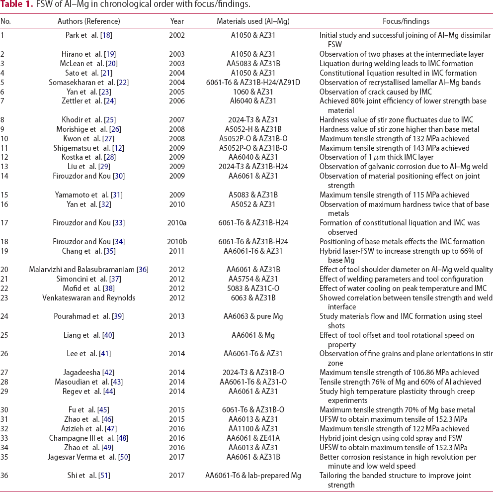
The analysis that follows attempts to extract information from these studies in order to derive observable trends. For example, careful study reveals that the main parameters such as tool rotational speed, welding travel speed and tool design vary greatly within the reported literature. Therefore, it is imperative that these FSW parameters are carefully analysed to tease out trends in the resulting Al–Mg dissimilar welds. However, to understand how parameters impact the joint outcome, it is essential to determine the fundamental aspects of the joining mechanisms and heat generation involved in dissimilar Al–Mg FSW. The following subsections address these issues in detail.
Joining mechanism in Al–Mg FSW
The joint strength in heterogeneous structures such as Al–Mg dissimilar welds primarily depends on two mechanisms, namely; the chemical bonding by the presence of IMCs, and; the mechanical interlocking due to the tortuous weld interface [16, 17]. These metallurgical and mechanical mechanisms are addressed below.
Incompatibility issues in Al–Mg FSW
An overview of the basic properties and incompatibility issues between aluminium and magnesium is useful to understand the chemical bonding mechanism. The key problem relates to limited solubility between Al and Mg, which consequently promotes formation of IMCs as indicated in the binary phase diagram for these elements.
Figure 1 shows the equilibrium binary phase diagram of the Al–Mg system [52]. Although it is well known that the welding process in general is a non-equilibrium process [53], the equilibrium binary phase diagram is regularly used as a guideline for prediction of stable phases and expected reactions during welding. The shaded areas in Figure 1 show the only composition of aluminium and magnesium where a single-phase (non-intermetallic) compound can be formed, i.e. successful solubility is achieved between aluminium and magnesium. Based on the trend of the solvus lines, it can be expected that the solubility of Al–Mg will be much lower at room temperature (not shown).
Equilibrium phase diagram of the Al–Mg system [52].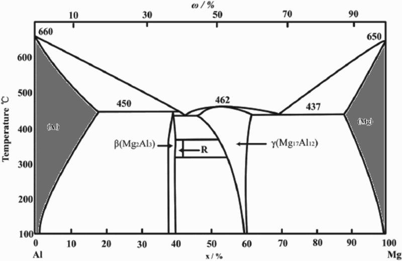
Several facts can also be interpreted from the phase diagram. It can be noted from the figure that the binary system contains two eutectic lines at 437 and 450°C, significantly lower than the melting points of pure Al and Mg. The diagram consists of three stable intermetallic phases, namely Al3Mg2 (complex cubic β) phase [54], Al12Mg17 (cubic of α-Mn type γ) phase and rhombohedral R phase (or sometimes referred to as ϵ-phase) [55]. Owing to the extremely limited solubility between aluminium and magnesium, a mixture of primary aluminium or magnesium phase can form in equilibrium with Al3Mg2 and Al12Mg17 phases during Al–Mg dissimilar welding. The IMC formation depends mainly on the local temperature and composition, despite the chemical composition of the initial base metal alloys. Therefore, microstructures and stable phases are difficult to predict and interpret since the exact peak temperature during welding is not typically known.
IMC layer and its formation mechanism
The most problematic issue that limits the strength of Al–Mg dissimilar FSW joints is the formation of brittle IMC layer at the faying surface of base metals. This complication is also associated with many other dissimilar joining processes, including diffusion bonding [56, 57], laser welding [15, 58, 59], friction stir spot welding (FSSW) [60, 61], resistance spot welding [62, 63], tungsten inert gas welding [64-66], metal inert gas welding [67], ultrasonic spot welding [68, 69], explosive welding [70] and cold metal transfer welding [71, 72]. IMC layers have shown to adversely affect the strength of the dissimilar joint. Formation of this layer is inevitable and almost impossible to inhibit; therefore, the best approach is to mitigate such compounds. In fact, other joining process such as transient liquid phase (TLP) bonding involves formation of the intermetallics for a short time as a requirement for the process to complete [73].
Kreimeyer and Sepold have suggested that an IMC thickness of less than 10 µm can be regarded as a mechanically sound joint [74], while Qiu et al. [75] also showed that joining of Al alloy to steel provided maximum joint strength when the intermetallic layer was only 1.5 µm in thickness. The typical IMC structure in Al–Mg joints consist of continuous overlapping layers of brittle Al3Mg2 and Al12Mg17 phases [23, 25, 26, 31, 39, 42, 46, 76]. Although it has been shown that Al12Mg17 exhibits extremely good ductility at high temperatures [77], after the joint is formed this phase accommodates negligible plastic strains near room temperature.
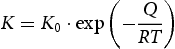
In the case of dissimilar Al–Mg FSW joints, the main theories provided in the literature to explain the IMC formation are based on either diffusion or eutectic reaction mechanisms. The debate concerning the dominant mechanism revolves around the argument of whether the peak temperature during welding exceeds the Al–Mg eutectic lines of 437°C (magnesium dominant side) and 450°C (aluminium dominant side). Yamamoto et al. [31] have argued that the FSW process remains below eutectic temperatures and thus the formation and growth of such compounds occurs by diffusion between Al and Mg atoms, producing eutectic layers. Therefore, the thickness of the layer is time-dependent and can be expressed as follows [78]:

 is the phase layer thickness (m),
 is the diffusion coefficient (m2 s−1),
 is the proportion constant (m2 s−1),
 is the activation energy (J mol−1),
 is the gas constant (8.314 J mol−1 K−1) and
 is the absolute temperature. Yamamoto et al. [31] have also demonstrated that the growth speed of Al3Mg2 is somewhat faster compared to Al12Mg17. However, this principle is largely based on a steady-state growth model for the lamellar structure formed when eutectic forms from a stagnant liquid. This does not necessarily apply to or explain the structures formed in the FSW process in which exceptionally large strains and strain rates occur near the tool surface.
On the other hand, the majority of studies have pointed out that eutectic reaction between both metals seems to be the main factor in the formation of the IMC phases [20, 21, 25, 27, 30, 33, 34, 47]. Evidence from these papers suggest that constitutional liquation/melting leads to IMC growth. As the eutectic lines are less than 200°C below the melting point of pure Al and Mg, sufficient heat is generated from the stirring action of the tool to induce local melting, i.e. eutectic reaction, forming thin liquid films which are able to propagate along grain boundaries as they do in the case of TLP bonding [73]. Depending on the local composition, IMC layers consisting of Al3Mg2 and Al12Mg17 are formed upon cooling as follows [30, 33]:
Al-dominant side (eutectic temperature 450°C): L → Al + Al3Mg2 Mg-dominant side (eutectic temperature 437°C): L → Mg + Al12Mg17
Mechanical interlocking
Mechanical interlocking is the mechanical bonding component in Al–Mg FSW that relies on forming a complicated geometry at the bonded surface to enhance mechanical strength. Owing to the complex geometry formed through plasticisation and shearing of base metals, mechanical interlocking has been reported to be one of the primary means in enhancing joint strength of other incompatible dissimilar welds, including welds involving Al–Mg [79], Al-steel [80, 81], Al–Cu [82] and Mg-steel [81]. Since low heat input is desired to maintain low temperature in order to impede IMC growth, formation of these mechanical interlocks between the intercalated layers is crucial to joint strength. Formation of IMCs at these interfaces can also enhance bonding through material mixing and stress distribution in the nugget zone. Tool design as well as tool and material positioning have been reported to enhance the formation of these mechanical interlocks [10, 31, 34, 40]. However, these structures do not acquire repeatable periodic structures like those formed by jetting of material during explosive welding [8].
The Al/Mg welding interface
As will be discussed in detail in the subsequent sections, the formation of these chemical and mechanical bonds in the welding interface varies significantly based on the material of workpiece, tool design and offset, as well as welding variables and setup. From the arguments above, it can be suggested that an ideal joint should consist of thin, intercalated IMC layers and complex mechanical interlocking. The thin brittle IMC layer may reduce the presence of defects at the weld interface, while a complex mechanical bonding promotes better stress distribution during loading and a more complex crack propagation path [79].
Given that a defect-free joint is desired without pre-existing cracks driven by the formation of IMCs and nucleated by residual thermal stresses [34, 40], in general, the bonding interface can be categorised in three groups based on the cross-sectional bond interface, namely; distinct boundary (hereafter designated as Type I); lamellar structure with distinct boundary (Type II), and; complex lamellar structure with distinct boundary (Type III). Figure 2 shows a schematic of these possible bonding interfaces.
Schematic of possible variations bonding interface of Al–Mg FSW; (a) Type I, distinct boundary, (b) Type II, lamellar structure with distinct boundary, and (c) Type III, complex intercalated lamellar structure.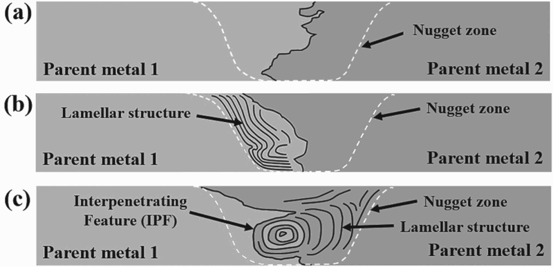
The Type I interface exhibits a distinct, tortuous IMC layer which segregates the base metals throughout the through thickness of the sample. Negligible mixing occurs between Al and Mg alloys in this interface. Owing to the concentration of brittle IMC directly at the interface, most of the reported cases exhibiting this feature will fracture at the bonding interface [26, 37, 39]. In Type II, a distinct boundary with the addition of lamellar structures consisting of base metals and IMCs can be observed. The lamellar structures are produced by enhanced material flow and intermixing between both parent metals. Type III is classified as joints with an observable interpenetrating feature (IPF) in the form of complex intercalated structure of the parent metals and corresponding IMCs resembling an onion-ring pattern. This pattern indicates optimum material intermixing and is usually accompanied by more lamellar structures at its periphery.
Among the three variations in bonding interface, Type III would be the most desirable, as this complex structure has the most potential to impede crack propagation by distributing the stress among the intercalated lamellar structures as opposed to distinct boundaries such as in Type I. Subsequent discussions will attempt to correlate these bonding interface types to the welding parameters and joint properties observed in the literature.
Owing to the complexity of the nugget zone microstructure, it will be challenging to quantify how the intercalated layers and mechanical interlocking contributes to the overall strength. However, Venkateswaran and Reynolds have suggested that tensile strength can be correlated to the ratio of total length of the weld interface (l) and sheet thickness (t), (l/t), as well as the ratio of the thickness of the IPF (h) and sheet thickness (t), (h/t). As shown in Figure 3, l is measured as the sum length of IPF and the kinked ligaments (white dashed lines), while h is measured parallel to the sheet thickness. An increase in both l/t and h/t ratio has a strong correlation with an increase in weld joint tensile strength. In addition, an increase in length and complexity of the interface seems to further strengthen the joint strength. Moreover, a larger h thickness increases the interface length and area of brittle fracture required to cause failure, strengthening the joint [79].
Cross sectional schematic of Al–Mg weld with IPF thickness (h) and weld interface length (l).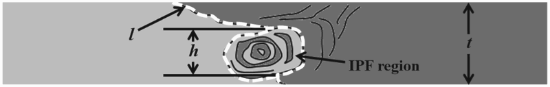
Heat generation in Al–Mg FSW
In FSW, heat is generated through three components which are plastic deformation (Ed) and friction (Ef) at the tool/workpiece interface as well as viscous dissipation (Ev). In dissimilar FSW such as Al–Mg, these components are governed by three aspects; a difference in friction coefficient; liquation susceptibility, and; deformability [45].
Zettler et al. have shown that the friction coefficient of the Al-tool interface was higher than the case of a Mg-tool interface. This suggests that the contributions of Ef and Ev during the process would increase if more interaction between Al and the tool is produced, for example by offsetting the tool to the Al side [24].
Yang et al. have calculated that liquation susceptibility of AZ31 Mg is higher compared to 6061 Al. When the eutectic temperature is reached in Mg–Mg FSW, the liquid films from the eutectic reaction Mg + Al12Mg17 → L at the tool/workpiece interface could cause tool slippage and interfere with plastic deformation by decreasing resistance to tool rotation. Therefore, heat generated through Ed, Ef and Ev all decreases, lowering heat input [83]. Furthermore, Fu et al. [45] claim the effect of constitutional liquation is dominant in Al–Mg dissimilar FSW, resulting in a lower heat input compared to similar Al and Mg FSW.
The difference in deformability of both metals can be explained through the crystal structure. Al has a face-centred cubic (fcc) structure with twelve slip systems, while Mg's hexagonal close-packed (hcp) structure offers only three slip systems. This allows better deformability for Al, leading to more heat generation through Ed and Ev [30, 45]. Zettler et al. [24] have demonstrated through similar-metal butt joint FSW that the stir zone of Al 6040 alloy was twice the size compared to the stir zone AZ31 Mg alloy, indicative of better deformability of Al.
Microstructural and mechanical characterisation
A summary of the microstructural observations is addressed in this subsection. Microstructural chara-cterisation is mostly focused on the weld nugget zone and its periphery. Dynamic recrystallisation (DRX) of Al and Mg grains were reported in the nugget zone, where a decrease in grain size compared to the parent metals below 18 µm is generally observed due to the stirring action of the tool [22, 24, 43, 47]. Grain size refinement as well as the presence of IMCs resulted in the general trend of an increase in hardness values in the weld area as compared to the parent metals.
IMC observations
The brittle IMC layers are reported to form either at the bonding interface or at the lamellar shear bands in the nugget zone. The thickness of the IMC layer observed ranges from 1 [28] to 3 µm [45], where it has been suggested that a sound weld may be formed with layers below the 10 µm [74] or even slightly above a thickness of 1.5 µm [75].
Kostka et al. [28] also reported nanosize-grained Al3Mg2 inclusions form in close proximity to the Al12Mg17 layer suggesting the existence of both brittle phases, in conformity with other research reports. However, the Al12Mg17 phase is more commonly observed compared to Al3Mg2 phase. This contrasts with what Yamamoto et al. stated earlier [31], but energy dispersive spectroscopy analysis points out that indeed the Al–Mg FSW joints undergo constitutional liquation and form IMC phases upon cooling [24, 25, 33]. More Al12Mg17 phase may have preferentially form due to its lower eutectic temperature [47].
Tensile strength
Mechanical properties data of Al–Mg dissimilar welding. Joint efficiencies are calculated relative to each base material (Al or Mg side).
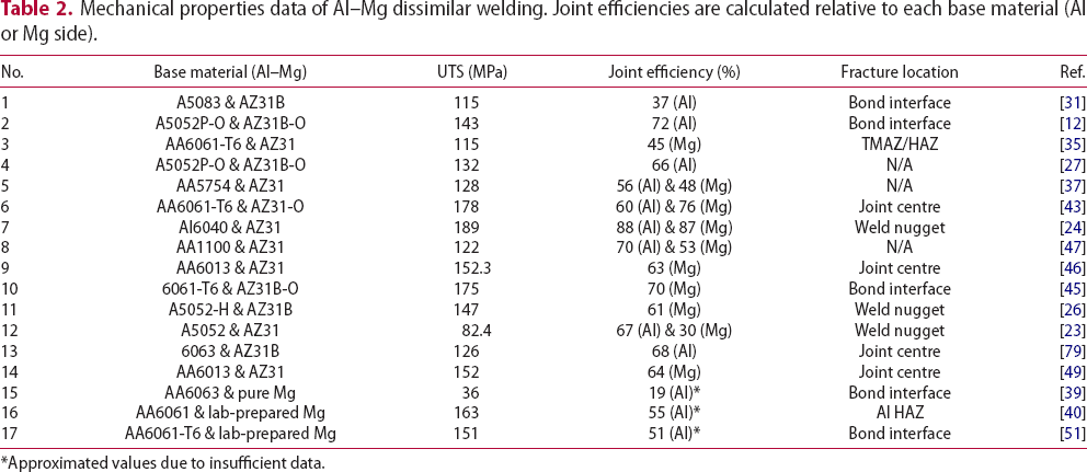
*Approximated values due to insufficient data.
From Table 2, it can be inferred that, with very few exceptions, an impressive joint efficiency can be achieved despite utilisation of diverse parent metals and welding parameters. Nevertheless, fracture location mainly occurring at the bonding interface and subsequent observations of the fracture surface (not shown in table) are clear indications of the presence of Al–Mg brittle IMCs which cause a detrimental effect on the weld integrity. In addition, the tensile elongation of joints during transverse tensile testing is generally significantly less than its parent metals, approximately 2% owing to the brittle nature of the IMC layers at the bonding interface [12, 27].
Some exceptions to the low elongation include studies by Pourahmad et al., Liang et al. and Azizieh et al., where maximum elongations are 4.5, 6 and 9%, respectively, [39, 40, 47]. In the former case, improvements were said to be due to the 1 h post weld heat treatment of 320°C. This potentially relieves the residual stress accumulated during the welding process, hence allows better elongation. However, this seems to be a poor trade-off, since the maximum tensile strength was only 36 MPa with joint efficiency of approximately 19% [39]. Liang et al. on the other hand observed better elongation when the fracture area shifted from the bond interface to the softened HAZ of the Al alloy, where necking before fracture was observed. The reason for the shift is unclear, but cross-sectional macrograph of these samples seems to show a Type III bonding interface. Owing to the complex geometry and large IPF, the strain during loading may have been evenly distributed to allow deformation on the soft HAZ alloy to initiate and preferentially yield first. No explanation was given for the high elongation reported by Azizieh et al., but this may also be due to the Type III interface obtained.
Defects, stress and failure mechanisms
Parameter optimisation and optimal welding setup are essential to produce a sound and defect-free Al–Mg joint. Among other factors, a crucial defect to avoid in Al–Mg FSW is the formation of wormholes and voids. FSW is a solid-state joining process, thus issues such as porosity due to gas vapour entrapment is not a concern. However, incomplete consolidation due to insufficient material flow may form sharp-cornered voids or wormholes which are stress concentration and crack initiation points [34, 39, 84]. This defect is particularly important to note since it is difficult to detect, while other defects such as surface flash or incomplete surface coalescence are surface defects and are easily observed.
Another aspect which is not commonly discussed is residual stress of the weld joint. Early experimentations by James and Mahoney [85] on similar Al FSW followed by several others have pointed out that the stirring action and plastic deformation during the FSW process would accumulate a sizable amount of residual stress which is potentially deleterious to the weld joint [86-88]. Pourahmad et al. [39] have proposed utilising post weld heat treatment to relieve residual stresses in Al–Mg FSW joints. Tensile strength was shown to increase after 1 h of heat treatment, but extensive heat treatment caused a decrease in strength and elongation due to growth of brittle IMC layers up to 23 µm. However, no residual stress measurements were conducted to support this claim and the high heat treatment temperature may have also promoted microstructural change that affects the outcome. To the authors’ knowledge, at present, no paper has been published specifically measuring residual stresses in Al–Mg joints, which maybe a potential research area of interest in the future.
Crack formation due to stress concentration has also been reported in the literature. Although not as severe as in fusion welding processes, local melting during FSW and the subsequent cooling could cause hot cracking if the stress around the locations where liquid film formed is high [21, 33, 40, 51, 89]. These cracks are also believed to be fracture initiation points and accelerate crack propagation through interlinking.
With the fabrication of defect-free joints, several researchers have analysed the fracture surfaces after tensile tests to identify the joint failure mechanism. Observations of quasi-cleavage/cleavage fractured surfaces in scanning electron microscopy images in several sources such as Masoudian et al. [43] and Shigematsu et al. [12] confirm the occurrence brittle-type fracture of the Al–Mg welds. Furthermore, several papers suggested that brittle fracture and crack propagation is linked to the brittle Al–Mg IMC layers at the weld interface [21, 42, 51, 90]. Shi et al. [51] have suggested tailoring of such banded structures of IMC to improve mechanical properties through parameter optimisation and modifying the bands to take on a relatively short, discontinuous and curved shape rather than straight arrangements to prevent easy crack propagation along these bands.
Effect of welding parameters
Several welding parameters are known to be crucial in providing a sound result, while others have been shown to have minimal effects on the Al–Mg FSW. Since welding variables will determine the effect on the joint properties mainly through heat generation and material flow, primary attention should be given to variables having the greatest effect on these aspects [1]. These welding setup and parameters are discussed below.
Base metal positioning
The orientation or position of the two metal workpieces on either side of the tool plays a crucial role in determining the FSW material flow and mixing as well as IMC formation during dissimilar welding [91]. In general, base metal from the front of the tool is transferred behind to the wake of the tool, producing a wiping flow mechanism [92]. However, the nature of the opposing forces on the advancing side (AS) mean that the direction of the translational motion and the tangent of the rotating tool surface is similar. In contrast, the retreating side (RS) is where the direction of the translational motion and the rotational motion is in opposite with each other.
Based on the Schneider–Nunes kinematic model [93], material on the RS is simply deposited directly behind the tool from the front, dubbed the ‘straight-through’ current. On the other hand, the material on the AS is drawn into the rotating tool, undergoing several rotations before finally being deposited at a lower position than the original height in a whirlpool-like manner, or commonly referred to as ‘maelstrom’ or whirlpool current.
In a typical similar butt joint FSW, it has been proven through simulations and temperature measurements that more heating occurs on the AS than the RS [94-97]. Owing to the stirring process undergone on each side, the material on the AS experiences greater shearing and heating compared to the RS [30]. Moreover, in similar Al and Mg FSW, Zettler et al. as well as Firouzdor and Kou have demonstrated that 6××× series Al alloys exhibit higher peak temperatures compared to its Mg counterparts. Other similar-metal FSSW of Al and Mg by Gerlich et al. and Yang et al. have shown a similar trend [60, 98].
Based on these facts, in can be stated that positioning of the different base metals either on the AS or the RS can produce drastically different microstructures and properties. In the case of Al–Mg FSW, two outcomes can be predicted, namely; a higher heat input can be expected with Al on the AS, and; a higher heat input can be expected when Al base metal and tool contact area increases, i.e. offsetting the tool on the Al side. In contrast, since higher shearing activity is expected in the AS, placing the Mg alloy which has a higher liquation tendency, lower friction of coefficient and lower deformability compared to Al alloys on this side suggests a lower heat input generation through Ed, Ef and Ev [10, 30, 34, 45].
In one of the initial developments by Sato et al., FSW butt joints between Al alloy 1050 and Mg alloy AZ31 were successfully produced [21] by placing AZ31 at the AS and 1050 at the RS, while exchanging their positions led to unsuccessful joining. Other subsequent reports have also suggested similar position setup [11, 24, 28, 30, 36, 40, 41, 44]. However, the majority of studies have advocated that placing aluminium on the AS and magnesium on the RS gives the best metallurgical quality [12, 20, 22, 23, 25-27, 29, 31, 32, 35, 37-39, 42, 43, 46, 49]. Such arrangement is said to promote higher welding process temperature and facilitates effective plasticisation [38].
From the specific aluminium alloys used, it appears that 2××× and 5××× series Al-alloys are always better suited on the AS, whereas 1××× and 6××× series are quite flexible in the positioning, even though many opt for placing it in the RS. This is possibly due to the low flow stress of 1××× and 6××× series compared to 2××× and 5××× series even at elevated temperatures. Figure 4 shows the UTS vs. melting temperature (Tm) fraction of Al alloys. Data were derived from [99]. The 1×××, 2×××, 5××× and 6××× series are represented by 1100-O, 2024-T3, 5086-O and 6061-O, respectively, where the UTS can be expected to approximate the flow stress. The flow stress of all alloys show a gradual decrease as temperature is increased to Tm. Even so, 2024-T3 and 5086-O shows a consistent high flow stress compared to 1100-O and 6061-O at elevated temperatures, since higher alloy content contributes significantly to flow stress at high temperature.
UTS vs. fraction of melting temperature (T/Tm) of Al alloys.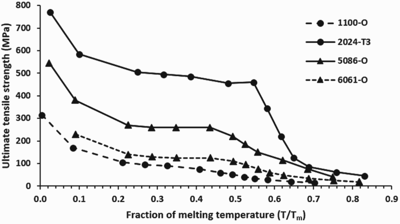
No comprehensive data were available for Mg alloys to compare the flow stress to Al alloys, but works by Sheng and Shivpuri [100] provided some data on the flow stress of AZ31B where the maximum flow stress at 200°C (0.52 Tm fraction) and 2.0 s−1 strain rate was reported to be approximately 220 MPa. Plotting this value in Figure 4 will reveal that the flow stress of AZ31B is similar to 5086-O at 0.52 Tm fraction. However, this value is only an estimation since the strain rates are not comparable. It can be expected that a lower strain rate will decrease the flow stress of AZ31B to a lower value. It should also be noted that higher temperatures will also activate more slip systems in the Mg alloys, and prior work has shown that for a wide range of tool rotation speeds, the torque generated by the tool in AM50 Mg-alloy is much lower than in Al 6061 alloy under the same conditions [98].
It can be summarised that the low deformation resistance (low flow stress) of 1××× and 6××× allows better consolidation and intermixing, regardless of base metal positioning. On the other hand, 2××× and 5××× alloys which have higher flow stress than its Mg counterpart which appear to make them better suited to be placed on the AS to enhance severe deformation and intermixing.
Tool design and offset
Tool geometry and positioning also play an equally important role in weld formation. The majority of studies highlighted in Table 1 utilise H13 steel tool, while other tools reported are high strength steel [23], HDS steel [42], SKD61 steel [25, 26, 31], SKD51 steel [35] and H13 shoulder with a MP159 cobalt base super-alloy pin [48, 79]. As for the tool geometry, the conventional cylindrical and threaded shape are both equally utilised. However, it is worth to note that most of the studies producing a Type III interface used pin with threads/flutes [24, 34, 40, 45, 47, 51, 79, 101, 102]. Threads and flutes on pin has been shown to enhance material flow in FSW, but also increase heat generation rate due to a larger interfacial area [103].
In addition, several studies opt for a concave shoulder. Lin et al. have demonstrated that microstructure and geometry of the weld may be significantly improved when the tool shoulder is concave rather than flat [104, 105]. Unique combinations of tool geometry such as threaded with 5-flats and 10° tapered pin utilised by Zettler et al. may have also contributed to the Type III interface formation and impressive welding efficiencies of up to 88% [24].
Literature shows slight variations with regard to pin length. The pin length to workpiece thickness difference, Δt, is generally small (Δt ≤ 0.5 mm), thus proper consolidation throughout the workpiece thickness can be expected. However, McLean et al., Yan et al. and Pourahmad et al. used a larger Δt of 1.4, 1 and 4 mm, respectively, [20, 23, 39]. A large Δt may result in inadequate consolidation/intermixing at the root weld and could promote premature failure. Evidence for this has been noted by McLean et al., who reported that the AA5083-AZ31B bond was rather weak, such that light forces from polishing were sufficient to cause a crack in the sample [20], while Pourahmad et al. recorded a joint efficiency of only 19% as shown in Table 2 [39]. On the other hand, Yan et al. [23] obtained a decent 67% joint efficiency, in part maybe due to better material flow through the use of threaded pin.
The conventional and most prominent approach in tool positioning is to traverse the tool along the faying surface centred between the two metals [12, 20, 24-26, 28, 43, 27]. Yamamoto et al. claimed that this positioning is favourable, since offsetting the tool towards the Al side or Mg side will form defects such as internal cavities and surface flash [31]. Nonetheless, several papers illustrate that offsetting the tool is an important consideration in Al–Mg FSW [30, 40, 44, 47]. Positioning of the tool with an offset from the material interface will determine the amount of material from both sides which will be consolidated in the weld mixture [10]; however, it is difficult to estimate by directly calculating the position of the expected stir zone area and areas overlapped by each material, since several material properties and tool design should also be taken into account.
Fu et al. [45] demonstrated using 6061-AZ31B that excellent intermixing (Type III) and sound weld between 6061-T6 and AZ31B can be produced when tool offset was 0.3 mm towards the Mg side. Azizieh et al. [47] also reported similar finding with AA1100 and AZ31 FSW, but with a larger offset of 2.5 mm. This may be explained through the relatively low flow stress of both Al series used mentioned earlier, where a relatively low heat input is sufficient to promote optimal material flow between base metals. Interestingly, studies regarding tool offset utilised only 1××× and 6××× series for the Al counterpart [23, 39, 45, 47, 51], further proving the ‘flexibility’ of these Al alloys.
Rotational speed and welding speed
The tool rotational speed, ω (rev min−1) and welding speed, v (mm s−1) are arguably the most important FSW parameters, since these have the most significant effect on the heat input and material flow. In general, heat input resulted from both parameters are correlated as:
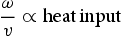
 ) in terms of the key parameter to produce quality results [106-108]. Using this ratio, a higher ratio value indicates a fast weld (also known as cold weld), while a lower value indicates a slow process (hot weld) [109]. Excessive pitch ratios will result in low peak temperature and inadequate material flow, while a very low ratio will cause unfavourable material flow and more liquation contributing to increase and growth of IMC layers, both detrimental to the weld joint [47, 83, 110].
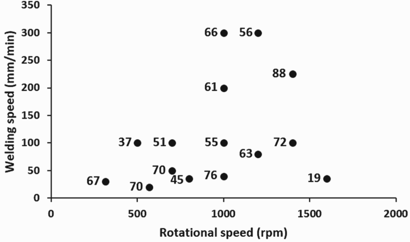
In the case of Al–Mg FSW, a range of 0.02–0.38 mm rev−1 have been reported in the studies in Table 1. The wide scatter of welding speed and rotational speed used makes it difficult to detect a general trend in the data. Figure 5 illustrates the welding speed vs. rotational speed plot from data taken from Table 2. The numbers adjacent to the data points represent joint efficiency of each data. The joint efficiency refers to the ratio between the UTS of the weld and the base metal UTS with the lowest value (i.e. highest efficiency). While no trend can be seen when correlating both parameters with joint efficiency, there seems to be an inclination to utilise low welding speed (≤100 mm min−1), although wide variations in rotational speed can be observed.
Further analysis can be made through observation of the joint efficiency, revolutionary pitch and resultant weld interface. Figure 6 shows the relationship between revolutionary pitch and highest joint efficiency of each data taken from Table 2. The circular, rectangle and triangle shapes represent Type I, Type II and Type III interface of each data point, respectively. In this regard, it is assumed that the cross-sectional interface of the tensile coupons used to determine the joint efficiency is similar to the cross-sectional macrograph reported in each paper.
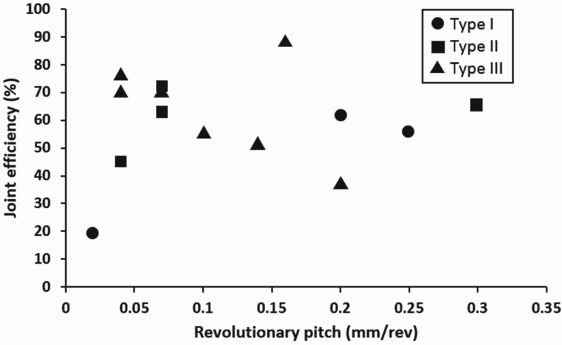
Among the data set used, only three are classified as Type I (poor) interface, while other data points show good (Type II) and excellent (Type III) intermixing. Judging from the trend, a wide range of revolutionary pitch can be applied to produce good to excellent joint interface. However, there seem to be a clustering of good joint efficiency with Type II or Type III intermixing when the revolutionary pitch is between 0.04 and 0.1 mm rev−1.
Correlating welding parameters to response variables
One can attempt to analyse each parameter in isolation to explore correlations with weld outcome. However, the fact remains that all parameters are compounded with each other to a certain extent. Subsequently, these parameters affect the process response variables such as torque, power, heat input and cooling rate, which in turn affects the material response. Several important response variables are discussed below.
Torque and power
Firouzdor and Kou have demonstrated that similar FSW joining of Al6061 produces significantly higher torque and power compared to similar AZ31 Mg FSW at similar parameter conditions [34]. In the case of Al6061-AZ31 dissimilar welding, torque and power increases with increasing travel speed. Both values were also significantly higher when 6061 is placed in the AS. This trend also resulted in an increase in heat input. However, an overall decrease in torque and power in dissimilar Al–Mg FSW resulted in lower heat input generation compared to similar joining of either metals. This suggests liquation from Al–Mg reaction as discussed earlier, which can cause tool slippage and explains the higher amplitude of torque oscillation due to ‘slip-stick’ phenomenon in dissimilar Al–Mg FSW [33, 111].
Venkateswaran and Reynolds studied the effect of welding parameters on torque and power asserted on 6063-T5 Al alloy and AZ31B-H24 Mg alloy dissimilar FSW [79]. Power is calculated by the product of the spindle torque and its rotational speed. It was suggested that there is a much stronger dependence on rotational speed since the torque has been shown to decrease as rotational speed was increased from 900 to 2700 rev min−1, which indicates a lower resistance to material flow as at higher speeds. This drop in torque is more than compensated by the increase in rotation speed since welding power increases with rotational speed, resulting in higher heat input to the weld nugget and increased subsequent grain growth in the nugget zone.
Peak temperature and cooling rate
Peak temperature measurements using thermocouples placed within the workpiece or inside the tool pin were conducted in several studies. Azizieh et al. placed a K-type thermocouple at the bottom of the workpiece to measure peak temperatures, which revealed that the best tensile results are obtained when the peak temperature were in the range of eutectic temperature (430–460°C) [47]. It was also noted that higher peak temperatures increased IMC formation and hardness of the nugget zone. With thermocouples embedded 3 and 2.5 mm away from the faying surface on each side, Firouzdor and Kou demonstrated that peak temperature is higher on the Al side regardless of base metal positioning. This was also later confirmed by Fu et al. [34, 45]. Temperature measurements conducted by Zettler et al. at mid plate thickness 10 mm from the weld centre also revealed a higher peak temperature in the Al side particularly when it is placed on the AS [24].
In a separate study, Firouzdor and Kou also reported that placing Al at the AS and offsetting the tool to the Al side will generate higher peak temperature, while placing the Mg alloy at the AS and offsetting the tool to the Mg will lower peak temperature. Subsequent tensile measurements show a close correlation between the increase in heat input and decreasing joint strength [33]. Fu et al. also reported an increase in peak temperature when a larger tool offset on the Al side was used, suggesting more heat was generated in the Al alloy [45].
Mofid et al. have reported a reduction of peak temperature and better weld quality by applying external water cooling on 5083 Al and AZ31C-O Mg FSW, while Zhao et al. have reported similar finding when an underwater FSW (UFSW) method was implemented on 6013 Al and AZ31 Mg FSW [38, 46, 49]. However, recent studies by Miyamori et al. have also demonstrated that UFSW of carbon steel produced higher z-axis loading and torque compared to conventional FSW because water cooling will limit the temperatures and likely increase the flow stress required for the deformation [112].
The cooling rate in a UFSW is faster since heat can be removed more rapidly through water [46]. A higher cooling rate implies that grain growth in the nugget and heat affected zone can be suppressed. It should also be noted that cooling rate may vary from top to bottom of the weld through thickness. Zettler et al. reported an increase in average hardness at the bottom of the 2 mm-thick Al6040-AZ31 FSW. This suggests a more rapid cooling rate compared to other regions of the workpiece, possibly due to direct contact with the backing plate which doubles as a heat sink [24].
Another probable approach to maintain peak temperature is through feedback control such as proposed by Ross and Sorensen [113]. A built-in thermostat ensures that a desired temperature is maintained by adjusting the tool rotational speed in real time. Not only does this maintain the temperature, it also decreased variation in properties throughout weld length, increased repeatability and prolongs tool life. However, despite its appealing benefits, this feedback system is complex and costly. To the authors’ limited knowledge, to date, there has not been any temperature control study on Al–Mg FSW.
Correlating multiple welding parameters to material response
A general summary consisting of several parameters and its effect on material response may lead to further understanding of fabricating the optimum joint. In this regard, joint efficiency (UTS ratio) is taken as the main material response criterion in defining a quality Al–Mg joint.
Figure 7 shows the joint efficiency-tool offset plot of papers tabulated in Table 2. The figure includes tool offset with no offset (with the tool centred at the faying interface) shown as a dashed line, while offset to the Al side or the Mg side is to the left and right of the dashed line, respectively. The circular, rectangle and triangle shapes represent the category (Type I, Type II and Type III) of interfaces produced in the weld. The closed shapes are configurations of Al on the RS and Mg on the AS, while the open shapes are the reverse, and the numbers adjacent to the shapes are the revolutionary pitch used. The interface type of the tensile coupons used to measure the weld joint efficiency is assumed to resemble the cross-sectional macrograph reported in each paper.
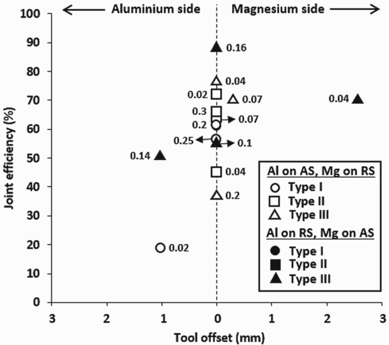
Based on the distribution of points in Figure 7, there is a clear preference to not apply offset and position Al on the AS, with Mg on the RS to produce good joint efficiency. It also illustrates dominance of Type II and Type III interface studies, suggesting the importance of good intermixing between parent metals. However, the data point with the highest reported efficiency contradicts this trend, and this outlier may be associated with the unusually high pitch [24]. Aside from this point, the majority of the highest joint efficiency values (≥70%) mainly consist of joints exhibiting the Type III interface. It seems that tool offset and placing Al on the RS can also be utilised to produce Type III interfaces, but as noted earlier, only low flow stress Al alloys such as 1××× and 6××× would be suitable for these situations. As for revolutionary pitch, a Type III interface with 70% joint efficiency can be achieved with a pitch as low as 0.04 mm rev−1. However, the quality of joint interface seems to downgrade to Type II and Type I when revolutionary pitch value reached 0.2 mm rev−1, with the lowest efficiency being 37%. The use of threaded pin may improve the outcome, since these studies utilised cylindrical pins [26, 31, 37]. Despite a high 0.3 mm rev−1 pitch, Yan et al. [23] utilised threaded pin to enhance flow and reported efficiency of 67%.
Summary
A comprehensive review has been conducted regarding Al–Mg dissimilar FSW. This review intends to provide insights for future endeavours in this field. Owing to the compounding effects of welding parameters and setup, these criteria can only be served as a general guideline. The summary and suggestions are as follows.
Weld interface
To facilitate the quantification of joint integrity, this paper suggests classifying the cross-sectional welding interface into three types, namely; distinct boundary (Type I); lamellar structure with distinct boundary (Type II), and; complex lamellar structure with distinct boundary (Type III).
Material selection
For Mg parent metal, AZ31 and AZ31B type alloys are the most commonly used. Although several Al alloy grades were introduced, the most versatile would be 1××× and 6××× series. Owing to its relatively low flow stress, these alloys can adapt to tool offset and base metal positioning change without compromising the joint efficiency.
Base metal positioning
Most studies opt for placing Al on the AS and Mg on the RS to produce the best metallurgical quality. However, higher heat input can be expected from this configuration.
Tool design and offset
A complex pin and shoulder geometry would enhance material flow of the nugget zone. Particularly, threaded pins seem to show enhancement of the joint efficiency due to better material flow. Other geometrical design to consider are flats for tool pin and concavity for tool shoulder. The majority of results with the highest joint strength have involved tool positions with zero offset.
Revolutionary pitch
No conclusive trend has been indicated between revolutionary pitch and dissimilar joint strength so far. However, good combination of joint efficiency and intermixing can be seen in welds with revolutionary pitch between 0.04 and 0.1 mm min−1.
Limiting heat generation
Suppression of excessive heat input has shown to improve joint integrity by limiting IMC growth and improve cooling rate. Some suggestions regarding this includes UFSW and temperature feedback control. However, both requires additional welding setup and may substantially increase the cost.
Footnotes
Disclosure statement
No potential conflict of interest was reported by the authors.