
Abstract
Dissimilar butted combinations of magnesium alloys AZ31, AZ61 and AZ80 were friction stir welded and transverse tensile tested until failure. Strain mapping across the deforming weld nugget and interfaces was carried out to correlate the deformation to the local microstructures. Mechanical performance was found to be highly dependent on the spatial distribution of alloys within the nugget and thus highly sensitive to changes in the tooling geometry. Process control requirements for repeatable, high-quality dissimilar friction stir welds will therefore be far more rigorous and challenging than those of similar welds of these alloys. In addition, proximity to the tool insertion point was found to decrease tensile performance, likely due to changes in tooling temperature.
Keywords
Introduction
Joining of dissimilar magnesium alloys broadens the potential applications by tailoring properties locally to the anticipated loading while maintaining the characteristic light weight advantage. The AZ series magnesium alloys are not considered fusion weldable [1] due to the formation of a brittle intermetallic phase, and so solid-state techniques such as friction stir welding are preferable.
While AZ series alloys are the most widely commercially available magnesium structural alloys, dissimilar friction stir welding research in this series is limited. Extrapolation from the wider body of information available for dissimilar aluminium friction stir welds is of limited use as many of the aluminium alloys are age hardenable, affecting the deformation and failure in ways that are not transferable to the magnesium AZ series, where age hardening has limited impact and much slower kinetics [2, 3].
Within the AZ series magnesium alloys, AZ31, AZ61 and AZ80 are all extrudable, resulting in a fine wrought structure and better mechanical properties than casting. With increasing aluminium content in the alloy, there is an increase in mechanical strength at the cost of ductility reduction. One aim of the current work is to investigate how the processing conditions affect achievable mechanical properties, with the aim of eventually improving them.
Of primary importance to the final mechanical properties is the selection of the alloys to be joined, as the base material properties determine the maximum achievable performance of the friction stir weld. Given a wrought starting microstructure, the properties of a dissimilar weld will be at best intermediate to the two base materials, or at worst, inferior to both. One example of this is the work of Liu et al. [4], who found their dissimilar AZ80–AZ31 friction stir welds had a UTS below that typical for either of the base materials used [5].
Although various authors have measured a lag before steady-state temperatures are reached around the friction stir welding tool [6-9], there is little information on the effect of this initial thermal transient on mechanical properties. Work by Bitondo et al. [10] reported that this transient had little effect on the mechanical properties of an AA2198 friction stir weld, however, no experimental work on this phenomenon in magnesium alloys has been found.
The purpose of this work is to investigate the effect of base material choices, distance from the weld start and processing conditions with the goal of providing a basic set of ‘best practices’ for the production and development of dissimilar magnesium friction stir welds with good mechanical performance, particularly for the AZ series alloys.
Experimental procedure
Various alloy combinations were butted parallel to the extrusion direction for welding. The base material was extruded sheets 4.9 mm thick by 15.2 cm wide, split along the centreline. Three base material magnesium alloys with ICP-AES determined compositions (wt-%) were used in this study: AZ31(2.67Al–0.77Zn–0.32Mn–0.01Si); AZ61(7.12Al–0.42Zn–0.35Mn–0.02Si); AZ80(8.77Al–0.44Zn–0.19Mn–0.02Si).
Friction stir welding conditions used a rotation rate of 900 REV MIN−1, tool tilt angle of 2°, and either 63 or 90 mm min−1 welding speed. Tool geometry is shown in Figure 1, and (as noted), a version of Tool B worn down by friction stir welding of metal-matrix composites was also used.
Triflat tools used in this study (dimensions in mm) had truncated conical pins, threaded outer surface and three 0.5 mm flats. Tool A (shown) resulted in a lack of penetration defect. Tool B, with no shoulder recess and pin length increased to 5 mm produced higher quality welds. Tool C was machined to the same design as B.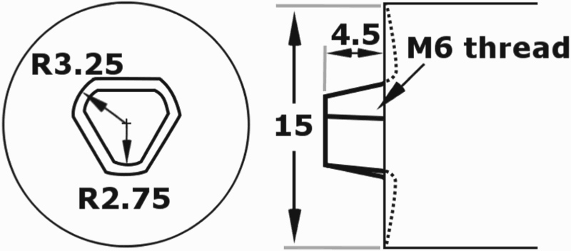
To assess the relationship between strain localisation and the microstructure, DIC (digital image correlation) was used to calculate strain across the sample based on images captured during tensile testing. Tensile samples were waterjet cut transverse to the extrusion direction, with sheet-type dimensions [11] and centred on the weld.
After cutting, samples became curved from the partial relief of transverse residual strains as detailed in [12]. While the axis of this bend was perpendicular to the plane of DIC examination, it caused non-linearity in extensometer measurements of strain for the initial loading curves. As accurate determination of yield was not feasible, strain localisation of 2% as measured from DIC is used instead for welded samples.
To accommodate simultaneous imaging of the weld microstructure and strain mapping, samples were first mechanically polished in the gauge length to a minimum finish of 1 µm before immersion etching in 1 g tartaric acid dissolved in 20 mL water for approximately 10 s to reveal the weld cross-section. Speckles were applied in a random pattern over the gauge length for DIC strain tracking purposes, with the optimum distribution found to result from matte black spray paint with a fan-type nozzle.
Initial DIC measurements used a Xenoplan 2.8/50-0902 lens to capture images during tensile testing, resulting in a spatial strain measurement resolution of approximately 0.9 mm2. Later measurements used a telecentric lens with a 17 mm field of view, resulting in a final spatial strain measurement resolution of approximately 0.24 mm2.
Strain analysis was performed using Matlab R2016a and the DIC code by Jones [13]. Comparison of DIC and extensometer measurements gave excellent agreement, and so for samples where no extensometer data was available strain and strain rates were measured from DIC data. Strain rates reported are averaged between the plastic 0.2% offset yield and failure. Videos showing DIC strain maps during deformation for selected tests are available online as supplementary material.
For comparison purposes, two base metal samples of each composition were waterjet cut from the extruded sheet transverse to the extrusion direction in the ASTM sheet-type dimensions and tested to failure at a strain rate of 4–5 × 10⁻⁴ s−1. The 0.2% offset yield, UTS and % elongation to failure were 113 MPa, 244 MPa and 16.2% for AZ31; 203 MPa, 309 MPa and 17.8% for AZ61; and 198 MPa, 340 MPa and 15.4% for AZ80.
As a convention, welds are shown with the advancing side (AS) to the left, and described with the AS material listed first, followed by the retreating side (RS) material. An S-suffix indicates the sample number, and a supplementary table of all conditions is available. Weld centrelines are marked on all micrographs. Note that due to weld variability, differences of up to 10 MPa are unlikely to be significant.
Results and discussion
Alloying content combinations
Initially, the effect of material selection was investigated, and in all cases significant loss of ductility and strength was observed compared to the parent material properties. Comparing the AZ80–AZ31–S2 friction stir weld to AZ80–AZ61–S12 to AZ80–AZ80–S16, the stress at which strain localisation occurred increased (from 106 MPa to 142 MPa to 155 MPa) as did the UTS (from 203 MPa to 221 MPa to 226 MPa) while the total elongation at failure decreased (from 3.7% to 2.7% to 1.6%), as expected from the base materials used.
The micrograph of AZ80–AZ31–S2 in Figure 2(a) shows the horizontal bands of intercalated AZ31 material drawn through the nugget by the action of the thread have reached as far as the AS interface, indicating the span of the welded nugget and the vertical orientation of the AS interface. In contrast, for AZ80–AZ61–S12 shown in Figure 2(b), most bands of AZ61 material have only reached part way across the nugget, without formation of clear intermixed layers, most likely due to the higher flow stress of AZ61 at elevated temperatures as compared to AZ31 [14]. In the case of the similar AZ80–AZ80–S16 joint shown in Figure 2(c), the internal structure of the nugget is not visible, however, the boundary of the fine-grained weld stir zone can be clearly seen to be vertical at the AS and RS up to the shoulder affected region near the top of the nugget.
(Top) Weld micrographs before testing. 2 mm scale bar shown in white. (Bottom) DIC strain maps of these samples, colorised from 0 to 10% equivalent strain, listed with applied tensile stress. 10 mm scale bar shown in black. (a) AZ80–AZ31–S2, (b) AZ80–AZ61–S12, (c) AZ80–AZ80–S16.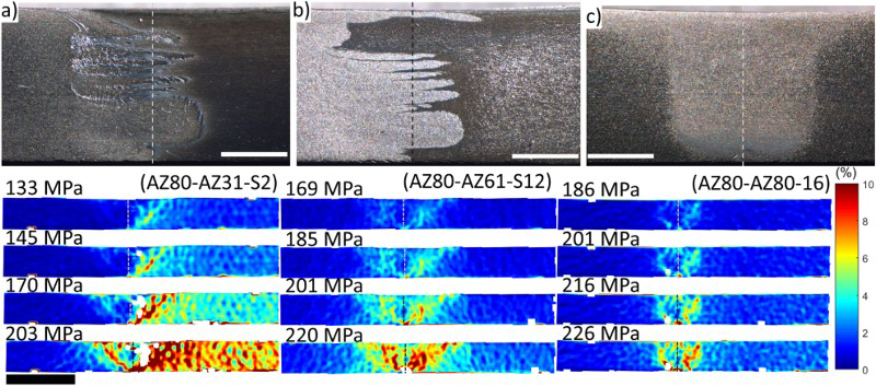
From the DIC images of Figure 2(a), it can be seen that strain in the AZ80–AZ31–S2 joint initially localised exclusively along the RS interface, before becoming distributed throughout the more ductile base material on the RS. When an applied stress of 145 MPa is reached, strain localisation at the AS interface became noticeable, at all times remaining lower in magnitude than that at the RS interface. Strain in the nugget centre was consistently much lower than at either of the interfaces, while the strain in the more ductile AZ31 base metal was unsurprisingly larger than in the AZ80 base material. For the AZ80–AZ61–S12 joint, the DIC maps of Figure 2(b) show that strain also occurred preferentially at the RS during the initial stages of deformation, before increasing along the AS interface. For this weld, strain within the AZ80 and AZ61 base materials was more symmetrical on both sides of the weld due to their similarity in Al content and ductility. For the AZ80–AZ80–S16 joint, behaviour was similar to the AZ80–AZ61 friction stir welds but more localised around the interfaces.
To determine the sensitivity of these tensile tests to the strain rate, additional lower speed tests were done in AZ80–AZ31 and AZ80–AZ61 at strain rates of 3.7 and 4.3 × 10⁻⁵ s−1 respectively. In both cases, little change was found in either the stress at which strain localisation occurred or UTS.
Effect of distance from the weld start
An additional parameter requiring experimental control was identified when three samples cut from an AZ80–AZ31 friction stir weld made at 900 REV MIN−1, 63 mm min−1, and tested to failure were found to have widely different tensile performance. As shown in Figure 3, with increasing distance from the weld start, the stress at which strain localisation occurred increased from 90 MPa to 99 MPa to 109 MPa, while UTS increased from 205 MPa to 230 MPa to 247 MPa, a behaviour likely due to an initial thermal transient in the friction stir weld. Fehrenbacher [8] and Kandaswaamy [7] report a decrease of tool temperature after the start of welding, while Darras [9] reports an increase. This disparity is likely due to changes in the initial dwell time, and possibly the tooling material [15], making the key point that changes in the mechanical properties may occur before steady state is achieved.
Tensile properties for samples AZ80–AZ31–S3 through S5. Inset bottom: Micrograph from AZ80–AZ31–S3, cut 0.8 cm from weld start, inset top: micrograph from AZ80–AZ31–S5 cut 5.8 cm from the weld start. 2 mm scale bars shown in white.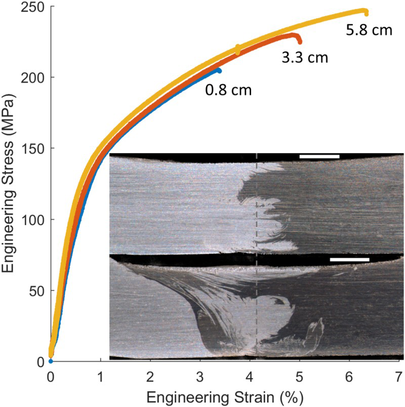
The dependence of mechanical behaviour on distance from the tool insertion point is further evidence that for high-quality process control in friction stir welds, real-time monitoring of the tool is a necessity [8]. Simulations by Yu et al. [6] estimated that for parameters of 600 REV MIN−1 and 66 mm min−1, a travel distance of 8 cm is required to achieve steady-state thermal conditions in AZ31. For the current work, a shorter distance to steady state would be expected given the higher rotation rates used, and so all welds discussed below were cut no closer than 6 cm from the start of the friction stir weld.
Atypically for these welds, the micrograph of the AZ80–AZ31–S3 joint (see Figure 3) has a basin-shaped profile. The significant quantity of AZ31 (darker material) along the AS interface and distributed through the nugget indicates greater intermixing of alloys occurred close to the weld start than for AZ80–AZ31–S5, cut further along the weld.
Effect of welding speed
To verify that optimum processing parameters found in previous work with AZ80 bead on plate welds [16] were applicable to the current tooling and dissimilar materials, joint AZ80–AZ31–S6 was made at 63 mm min−1 and compared to AZ80–AZ31–S7 made at 90 mm min−1. The tensile performance of both welds was nearly identical at lower strains, with strain localisation occurring at 75 MPa and 79 MPa for the 63 and 90 mm min−1 conditions respectively. However, the 63 mm min−1 friction stir weld had inferior performance, with a UTS of 216 MPa and strain to failure of 4.8% over the 50 mm gauge length as compared to the 90 mm min−1 sample, which had a UTS of 229 MPa and strain to failure of 6.1% over the 50 mm gauge length.
Comparing the strain maps for the two welds, at a stress of 145 MPa both show strain starting to localise at the RS of the top of the weld, where fracture will later initiate. The strain map of AZ80–AZ31–S6 shows an additional band of high strain concentration on the AS aligned with the band of AZ31 traversing the top of the nugget, which is particularly visible at later stages of deformation. At a stress of 183 MPa, the path that fracture will follow in AZ80–AZ31–S6 is clearly visible as an ‘S’ shape band of high strain at the RS of the weld. In contrast, for AZ80–AZ31–S7, the strain is more homogeneously distributed in the RS material, and no contiguous bands of high strain are present on the AS at all.
Fracture in the AZ80–AZ31–S7 joint initiated at the top of the weld on the RS and proceeded directly towards the RS interface root at 45° to the loading axis as is typical for ductile shear failure. For AZ80–AZ31–S6, the initial fracture path was identical, but partway through the material thickness, the fracture doubled back into the surrounding base material on the RS before proceeding jaggedly through to the base surface.
Comparing the distribution of AZ31 for these two welds provides a microstructural basis for the different strain localisation behaviour. For the AZ80–AZ31–S6 joint, the interface between the two materials is generally angled from the band of AZ31 crossing the nugget near the AS shoulder, downwards towards the root of the RS. This will promote shear deformation of the more ductile AZ31 material, leading to the band of high strain seen for AZ80–AZ31–S6 at 183 MPa, and earlier failure. In contrast, the additional band of AZ31 flow in AZ80–AZ31–S7 (see arrows in Figure 4) effectively made the interface more vertical, extending strain localisation at the RS before failure. From this, it becomes evident that for dissimilar welds minor changes to the flow of material and to the spatial distribution of materials in the nugget will result in major changes in strain localisation and mechanical performance.
(left) AZ80–AZ31–S6, 63 mm min−1 (right) AZ80–AZ31–S7, 90 mm min−1 (top) micrographs of the friction stir welds with arrows marking the extent to which AZ31 has been moved across the lower portion of the nugget for each weld. 2 mm scale bars shown in white. (bottom) Maps of the equivalent strain at stresses of (top to bottom) 145 MPa, 164 MPa and 183 MPa, same strain scale for all figures. For ‘x’ marks, see Figure 5(c).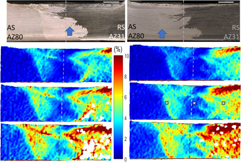
In contrast to previous work [16] that showed more heat input improved the mechanical properties of defect-free similar AZ80 friction stir welds, the current results show that higher heat input is not necessarily better for dissimilar AZ80–AZ31 welds. It is evident that the spatial distribution of AZ80 and AZ31 within the stir zone dominates the deformation behaviour instead of texture or residual strain, resulting in different overall trends.
Effect of alloy combination on defect formation and deformation
Using a worn tool to make the similar AZ31–AZ31–S10 friction stir weld (Figure 5a) resulted in the formation of a small wormhole defect along the centreline due to the erosion of both pin length and features which promote stirring [17]. The threads of the pin force downward motion of the softened material [18] and improve material flow around the pin [15], and a lack of downward force contributes to the formation of defects at the weld root [17].
(a) Similar AZ31–AZ31–S10 friction stir weld made at 900 REV MIN−1 and 90 mm min−1 using a worn version of Tool B. Micrograph and map of the equivalent strain at 108 MPa, see Figure 4 for strain scale. 2 mm scale bar shown in white. (b and c) Plots of local strain at the interfaces and nugget centre as compared to the global tensile strain for (b) similar AZ31–AZ31–S10 and (c) AZ80–AZ31–S7. See strain maps for measurement locations, marked with ‘x’ above and in Figure 4.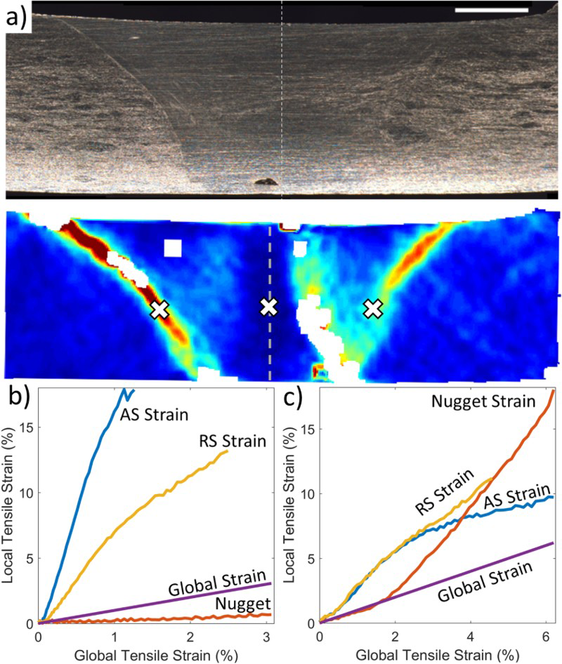
With increases in the alloying content of AZ series alloys, the ductility decreases and the processing window for defect free welds becomes more limited [19], and so it is unsurprising that when the same worn tool was used on dissimilar AZ80–AZ31 welds (not shown), wormhole defects of larger size were formed, and mechanical performance was poor.
Similarly, for dissimilar friction stir welds made with a worn tool, placing the more ductile material on the RS (AZ80–AZ61–S14) results in a smaller defect than the reverse situation (AZ61–AZ80–S15). Liu et al. [4] attributed comparable results in dissimilar AZ31–AZ80 friction stir welds to the greater difficulty of moving material from the RS to the AS as opposed to the opposite direction, which is somewhat relieved by selecting the more deformable material for this task.
Comparing the weld morphology, the interfaces of the similar AZ31–AZ31–S10 weld are far more sloped than those of a weld made in stiffer material (e.g. Figure 2c) and those of a good quality dissimilar weld (see AZ80–AZ31–S7 in Figure 4), showing that flow around the tool is heavily affected by the alloy.
The strain distribution in AZ31–AZ31–S10 shows bands of high strain at both interfaces (see Figure 5a). Typically for a similar friction stir weld of reasonable quality, failure in the AZ31–AZ31–S10 joint occurred along the AS interface. Plotting local deformation at selected locations in AZ31–AZ31–S10 (see Figure 5b), strain is greater at the AS interface where failure will occur than at the RS interface. The reverse situation will occur if the shoulder region is removed as shown by Liu et al. [20], due to the resulting redistribution of strain and texture across the weld. In comparison, for the good quality dissimilar AZ80–AZ31–S7 weld (see Figure 5c), the two interfaces had similar levels of strain for most of the test.
In the nugget centre of the similar weld, deformation remained at all times lower than the global average, while in the dissimilar weld strain spreads through the nugget and it deforms significantly during the later stages of deformation. The dissimilar friction stir weld had superior mechanical properties, which is attributed mainly to the more distributed nature of strain in this weld as compared to the similar weld. The small wormhole defect of the AZ80–AZ31–S7 weld is unlikely to have notable impact on deformation due to being located in a region of extremely low local strain.
Summary and conclusion
During tensile testing of high-quality dissimilar AZ-series friction stir welds, high localised strains occur first under the RS shoulder, before spreading through the RS base material and the RS of the nugget. At about this stage, strain increases at the AS interface and that side of the nugget while continuing to intensify in other locations. Near failure, strain is highest on the RS spanning the interface, high in the AS of the nugget and low in the centre of the nugget (see Figure 4). Failure will occur in the softer material on the RS oriented at 45° to the applied load.
In contrast, for a good quality similar friction stir weld, strain first localises along the top portion of the AS interface and intensifies. Later, strain localisation at the top of the RS interface becomes apparent, remaining at all times lower than at the AS interface. As stress increases, strain begins to spread towards the nugget centre (see 5a), but is generally low here due to poor orientation for basal slip [16]. Failure will occur by delamination of the AS interface.
For a similar friction stir weld, the greatest transverse strain is limited to two narrow bands aligned with the interfaces, while for dissimilar friction stir welds strain is far more distributed in the base metal at the RS.
As expected, friction stir welds involving AZ80 were found to be more prone to the formation of defects than those using more ductile material such as AZ31, and placing the more ductile material on the RS was advantageous. In one sample, joint efficiency of 101% was achieved, but properties are significantly affected by proximity to the friction stir weld start and tool wear which was found to be associated with the formation of void-type defects such as wormholes.
The conditions of 900 REV MIN−1 and 90 mmmin−1 were found to be superior to parameters of 900 REV MIN−1 and 63 mm min−1 for joining these alloys, and strain mapping of the deformation behaviour showed tensile behaviour to be well correlated with the spatial distribution of material in the nugget. It is the conclusion of the authors that in these dissimilar friction stir welds the distribution of nugget material has far greater impact on the mechanical performance than finer microstructural features such as grain size and texture. It is therefore anticipated that minor changes in the flow and resulting final distribution of material will result in major changes to the mechanical performance of the friction stir weld. In other words, mechanical performance of a dissimilar friction stir weld will be extremely sensitive to minor alterations of the tooling and material layout: far more so than a similar friction stir weld.
As a final note, sensitivity to initial thermal transients is of great interest to practical manufacturing applications of friction stir welding and has been shown to extend for at least 3 cm from the weld start in the current case but potentially much farther. Work with an instrumented thermocouple and additional tensile testing would be valuable to investigate this effect.
Footnotes
Acknowledgements
This work was supported as project C504-CTW by Auto21 and by grants from NSERC. Special thanks to Scott Shook for providing the AZ Mg alloys used in this study.
Disclosure statement
No potential conflict of interest was reported by the authors.