
Abstract
Enhancing the heat transfer to the material being welded, instead of the tool, will improve the welding thermal efficiency. Friction stir welding of 5 mm thick 6061-T6 aluminium alloy plates was carried out with the newly produced tools. It was found that the thermal efficiency increased by 4.2% using a tool with all the new design features (i.e. hollow, fluted and thermally insulated) compared to the conventional tool for aluminium welding. To assess the benefits of the new tool design on steel FSW, a finite element numerical simulation study was undertaken. In this case, the simulation results yielded a welding thermal efficiency increase of 10–15% using a thermally coated tool, thereby offering potential productivity gains.
Introduction
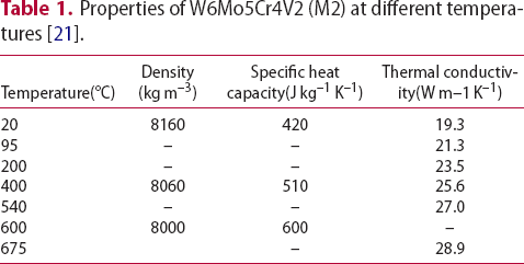
Properties of W6Mo5Cr4V2 (M2) at different temperatures [21].
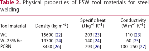
Physical properties of FSW tool materials for steel welding.
Thermal efficiency of FSW from literature.
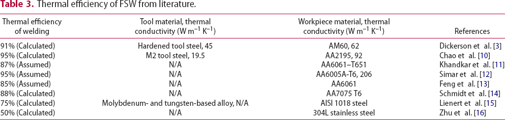
In all cases, the above-discussed literature employed conventional FSW tooling as part of their studies. However, previous works [17-19] indicated that the geometry of tool influenced the weld quality and process response during welding. In a prior published work of this research group [20], 12 FSW tools with different geometric structures were investigated. By comparing the numerically predicted temperature distributions of the tool to the experimental results, it was found that reduction in the heat dissipation from the tool was achieved through the application of thermally insulated tooling. As an extension to the previous research [20], the present study explores the gain in thermal efficiency when a combination of thermal barrier coatings and geometrical changes to the FSW tool design are implemented.
Methodology
Tool design
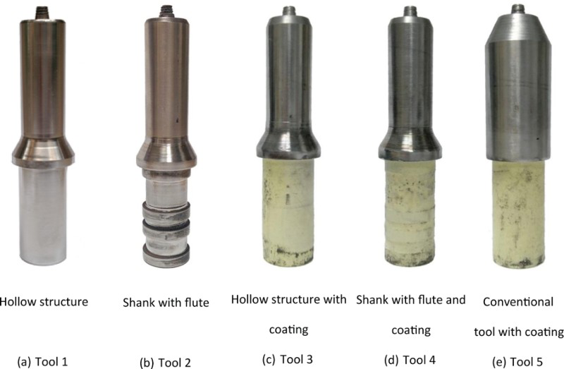
Based on the FE heat transfer simulations in Ref. [20], the following modifications to the conventional FSW tool (Figure 1(a)) were found to be effective in reducing the tool heat loss. The first was the reduction of its main body diameter. Additionally, a hole was drilled along the tool centreline. The purpose of these modifications was the reduction of the cross-sectional area (Figure 1(b)) and corresponding conducted heat. To further decrease the heat conducted to the tool shank, a series of grooves were introduced (Figure 1(c)). A Y2O3 stabilized ZrO2 thermal barrier coating was plasma sprayed on the tool shank surface to improve the insulation performance of the tool. Five tools with these thermal insulation features were fabricated as shown in Figure 2.
FSW tools with different structures. Fabricated FSW tools with heat insulation features.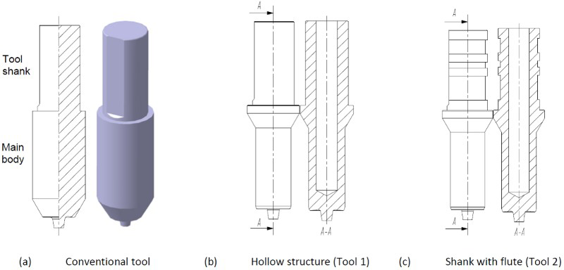
Temperature measurements
Aluminium alloy 6061-T6 plates of 300 × 75 × 5 mm were used as the workpiece and these were friction stir welded with the parameters: rotational speed, 800r min–1, traverse speed, 30 mm min–1, plunge depth of the shoulder, 0.3 mm. Since it is inconvenient to measure the temperature of the rotating FSW tool with contact type sensors, a FLIR A320 infrared thermal imager was utilised to obtain the temperature field of the tool. The welding plate temperature was measured by inserting K-type armoured thermocouples into the measurement hole drilled on the surface of the plate.
Thermal modelling
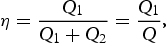
The welding thermal efficiency depends on the heat power into the workpiece and the tool as discussed in the introduction section. These were calculated by independent heat transfer models for the tool and workpiece. The models were created in Abaqus with DC3D20 heat transfer brick element. For the tool thermal model, both the tool and tool holder were included in the analysis as illustrated in Figure 3. The temperature-dependent thermal properties of the tool materials for welding aluminium was given in Table 1 and constant tool material properties were used for steel welding and shown in Table 2.
FE model.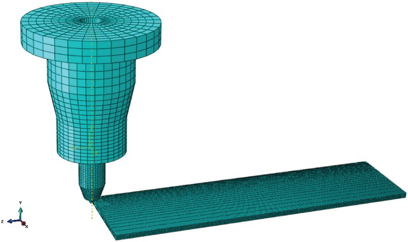
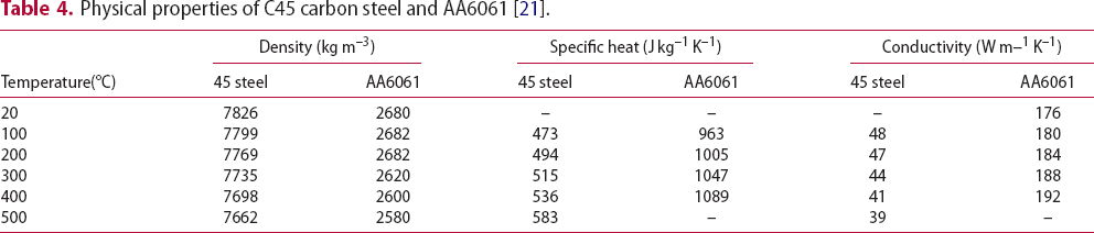
Physical properties of C45 carbon steel and AA6061 [21].
Results and discussion
Comparison of FE and experimental results
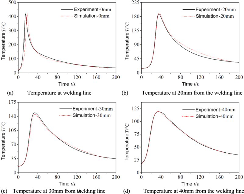
The comparison between infrared thermal measurements and the FE temperature contour plot for steady state FSW of AA6061 is presented in Figure 4. As mentioned in a prior publication [20], the temperature values at five selected points on the tool holder were shown on the images and good agreement was found between the two set results. Thus, the heat power transferred into the tool can be calculated through the applied heat flux. When the temperature profiles in the workpiece between thermocouple measurements and the FE model prediction are in good agreement, the sum of the shoulder heat flux and pin volumetric heat generation can be seen as the total heat input into the workpiece. Figure 5 presents the temperature comparison for the aluminium workpiece at distances of 0, 20, 30 and 40 mm from the weld centreline.
Comparison of temperature between experiment and numerical model. Comparison between experimental and numerical temperature evolution for the AA6061workpiece.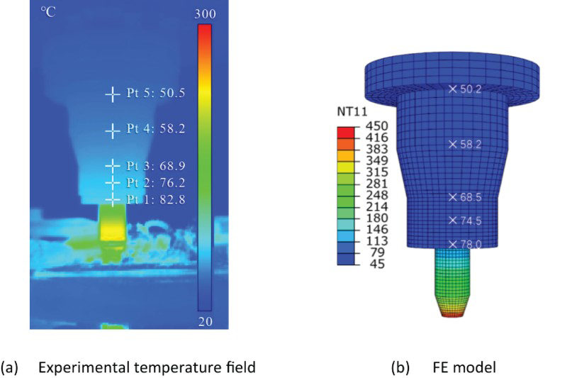
Thermal efficiency for welding aluminium plates
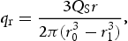
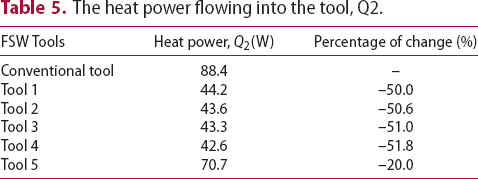
The heat power flowing into the tool, Q2.
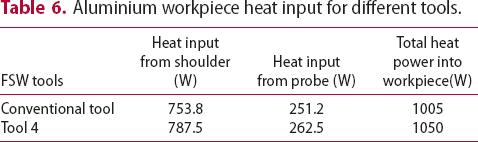
Aluminium workpiece heat input for different tools.
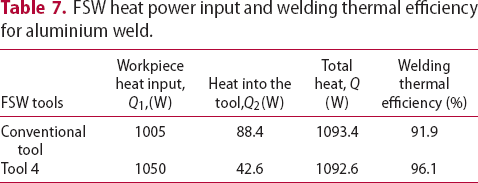
FSW heat power input and welding thermal efficiency for aluminium weld.
Thermal efficiency for welding steel plates
FSW heat power input and welding thermal efficiency for steel weld.
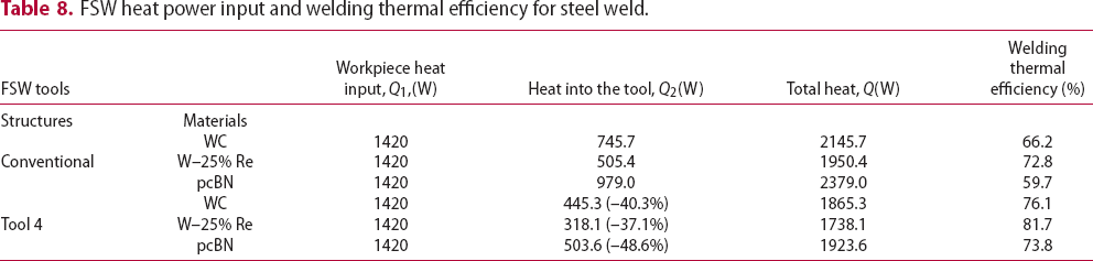
The heat into the WC tool, Q2, decreased from 745.7 to 445.3 W, and the thermal efficiency increased from 66.2 to 76.1%; these signify a 9.9% improvement in thermal efficiency for the new tool design. Similar trends were also found for the W–25% Re and pcBN tool materials. Among the three tool materials, pcBN seemed to be the best choice because of the 48.6% heat reduction into the tool (Table 8).
Conclusions
Heat transfer models for both the FSW tool and the workpiece were developed to calculate the heat transferred into the tool and the heat power input to the workpiece. The numerical model for aluminium welding was validated by experimental temperature profiles measured with an infrared camera and thermocouples for the tool and workpiece, respectively. Several thermal insulation features were applied to the new tool designs, such as low conductivity tool coating, smaller tool main body diameter, hollow structure and grooves on tool shank. It was found that the tool structures with thermal insulation features reduced heat flow into the tool as much as 50%, and improved the welding thermal efficiency up to 96% for aluminium welding under the current experiment conditions. The thermal efficiency for FSW of steel was much lower than aluminium plates, ranging from 59.7 to 81.7%. Compared with conventional tools, the new tool design improved thermal efficiency by up to 4.2 and 14.1% for aluminium and steel workpiece, respectively.
Footnotes
Disclosure statement
No potential conflict of interest was reported by the authors.