
Abstract
Low-transformation-temperature (LTT) fillers with various martensitic transformation start (Ms) temperatures were used to produce fillet welds. In comparison with conventional welds, the fatigue strength of the LTT fillet welds offers a significant improvement, with a minimum increase of 145%. Owing to the substantial dilution of base metal, the Cr and Ni alloying elements in the LTT weld metals decrease, resulting in an increase of the Ms temperatures. Therefore, the fillet welds produced using the LTT filler material with the lower Ms temperature (92°C) exhibit a larger compressive residual stress and higher fatigue strength.
Keywords
Introduction
Welding residual stresses are common concerns in welded high-strength steel structures, because tensile residual stresses tend to reduce the fatigue strength of welded joints [1, 2]. Low-transformation-temperature (LTT) fillers can reduce the tensile welding residual tensile stress or, in some cases, even introduce a compressive residual stress to the weld zone [3-7]. Meanwhile, the fatigue strength of high-strength steel welded joints has been significantly improved by using LTT fillers [8-11]. In the past two decades, significant progress [12-14] has been made in the development of LTT fillers. Recently, Moat et al. [15], Jonny et al. [16] and Jiang et al. [17] further demonstrated the advantages of LTT fillers in lowering the tensile residual stress and producing significant compressive residual stresses. Harati et al. [18] further demonstrated that the LTT consumables could successfully increase the fatigue strength of welds in high-strength steel with a yield strength as great as 1021 MPa.
LTT fillers induce transformation plasticity at sufficiently low temperatures, which compensates for thermal contraction strains and thus reduces the degree of the tensile residual stress in welded constructions [3, 19, 20]. Previous works [21-23] indicated that the martensitic transformation start (Ms) temperature of a given LTT filler is an important factor when seeking to control the level of residual stresses. Not only can the LTT fillers with suitable Ms temperatures eliminate tensile residual stresses by reducing these stress to zero, but such fillers can also introduce compressive residual stresses. Ohta et al. [24] developed LTT wire with 10% Ni-10% Cr as the main alloying elements, resulting in an Ms temperature of 180°C and high volume expansion. Wang et al. [25] found that the Ms temperature of an LTT filler material should be approximately 190°C to obtain the largest benefit from the transformation-induced volume expansion. Murata et al. [26] observed the volume expansion to reach a maximum value when the Ms temperature of the LTT filler alloy was on the order of 200°C. Therefore, it was expected that the Ms temperature of the LTT filler could be designed to be close to 200°C by controlling the content and type of alloying elements [27].
Most of these studies [21-23, 25] investigated the relationship between the Ms temperature and volume expansion of the LTT filler material without considering the influence of base metal dilution. However, for welded joints, especially in single-pass fillet welds, the alloying concentrations of the LTT weld metals are distinctly different from those of the LTT filler material due to the high degree of dilution [12]. The Ms temperature depends on the content and type of alloying elements [27]; therefore, even when the Ms temperature is designed to be approximately 200°C for the LTT filler material, this temperature will be far away from 200°C for the weld metal. As a result, the benefits of the LTT filler material used to control the residual stresses and improve the fatigue strength will be weakened. Recently, Harati et al. [18] found that the single-pass fillet LTT welds produced with LTTS (Ms temperature of 87°C) had a higher fatigue strength improvement than that observed in the LTTM (Ms temperature of 169°C). The results were attributed to the fact that the Ms temperature of the LTTS weld metal was increased to nearly 200°C due to the high degree of dilution.
Considering the influence of dilution, the ideal Ms temperature, which would be close to 200°C to be suitable for the LTT weld metal, may not be optimal for the LTT fillers. Therefore, the effect of dilution should be considered in the development of LTT fillers and their application. Until now, limited research has focused on the effect of dilution on the residual stress and fatigue strength of LTT welds. In the present study, therefore, different LTT filler wires with various Ms temperatures were prepared. The effect of dilution on the residual stress and fatigue behaviours of LTT welds was investigated.
Materials and methods
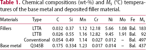
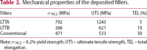
Q345B steel was used as the base metal for the fabrication of longitudinal stiffener fillet welded joints. Two developed LTT filler wires (LTTA and LTTB) [28] and one conventional filler wire (TME 711) were chosen. The chemical compositions and Ms temperatures of the base metal and deposited fillers are presented in Table 1. The chemical compositions were measured by optical emission spectrometer (Mode: SPECTRO LAB LAVM10), and the Ms temperatures of the deposited filler material are evaluated according to Equation (1) [29]. The mechanical properties of the deposited fillers are given in Table 2.
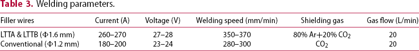
Dimensions of the longitudinal stiffener fillet weld specimens (all dimensions in mm) and the measured locations of residual stress, hardness and microstructure. Chemical compositions (wt-%) and Ms (°C) temperatures of the base metal and deposited filler material. Mechanical properties of the deposited fillers. Note: σY0.2 – 0.2% yield strength, UTS – ultimate tensile strength, TEL – total elongation. Welding parameters.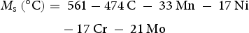
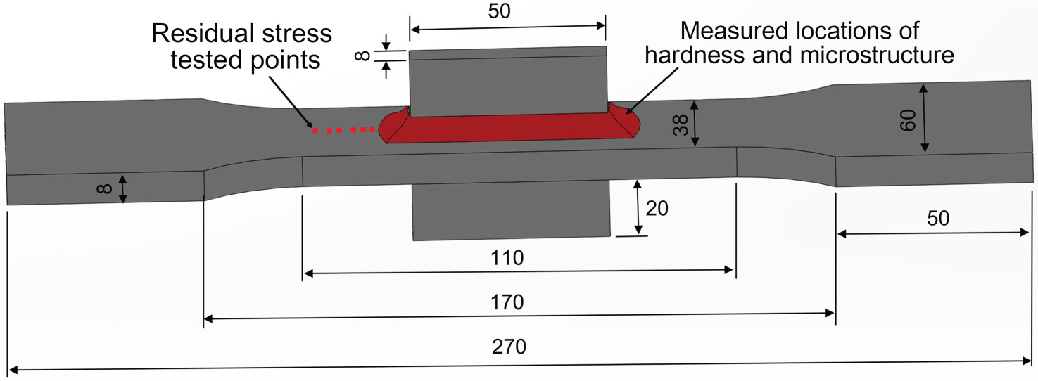
Fatigue tests were carried out under constant amplitude loading in a 300 kN HF fatigue testing machine at ambient temperature. The stress ratio (R) was 0.1 at ambient temperature. The test was stopped if the cycles reached 107 and the specimen was regarded as ‘run-out’. The Weld Impression Analysis method was used to measure the weld toe radius and angle on the two opposite sides of the web [30, 31]. For each group, 10 specimens were measured in a stereomicroscope with 20× magnification. The longitudinal residual stress along the centre line of the flange was measured using X-ray diffraction according to the sin2ψ method. A PROTO IXRD-MG40 X-ray Stress Analyzer with Cr-Kα radiation was used to measure the (211) diffraction plane of the ferrite phase, and the ψ angle is between −25° and + 25° (more than 7 angles in total). The diameter of the collimator is 1 mm. The measurement locations for the tested residual stresses are shown in Figure 1.
The microstructure of LTT weld metals was observed by scanning electron microscope (SEM) and the electron backscattered diffraction (EBSD). An etching solution consisting of 5 g FeCl3, 15 ml hydrochloric acid and 60 ml distilled water was used to etch the samples for SEM. The samples used for EBSD were electro-polished with a solution of 95 vol.-% alcohol and 5 vol.-% perchloric acid (voltage of 30 V). The EBSD samples were analysed by TSL-OIM analysis software and the data was acquired using an accelerating voltage of 20 kV and a step size of 0.2 μm. The volume fractions of the retained austenite were evaluated by X-ray diffraction (XRD) with Cu-Kα radiation from 35° to 120° at a step interval of 0.02°. To avoid the influence of the surface state, the samples used for XRD were electro-polished at 30 V for 20 s in a solution of 95 vol.-% alcohol and 5 vol.-% perchloric acid. The hardness values of the weld metals and deposited fillers were measured using the Vickers hardness tester with a load of 10 kg and a dwell time of 15 s. Hardness maps of the LTT joints were produced using micro-hardness tests with an applied force of 200 g. The measurement locations for the microstructural observations and hardness samples are shown in Figure 1.
Results
Fatigue life
The fatigue test results and the fitted S–N curves are shown in Figure 2. The fatigue lives of the welds produced using the LTT filler wires are higher than those of the welds produced by the conventional filler wire. The fatigue strength at two million cycles and the slope of the curves are presented in Table 4. By comparing the LTT welds with the conventional welds, characteristic fatigue strength (FAT) improvements of 145% and 150% are achieved for the LTTA and LTTB welds, respectively. The S–N curve slope of the LTTA welds (m = 16.2) and LTTB welds (m = 14.4) are larger than the slope (m = 3.5) of conventional welds. The LTT welds with the low Ms can induce a volume expansion that compensates for the thermal contraction strains during cooling to ambient temperature. As a result, the harmful tensile residual stress in the weld toe can be reduced effectively. The LTT welds produced using the LTTB filler exhibit a higher fatigue strength, indicating that the LTTB weld offers an appropriate Ms temperature for inducing a larger volume expansion and reducing the harmful tensile residual stress.
S–N curves of the longitudinal stiffener fillet welded joints produced using the LTT and conventional fillers. Fatigue strength at 2 million cycles and slope of the curve. Note: FAT – the calculated characteristic fatigue strengths corresponding to 95% survival probability at 2 × 10⁶ cycles to failure, the mean fatigue strengths corresponding to 50% survival probability at 2 × 10⁶ cycles to failure.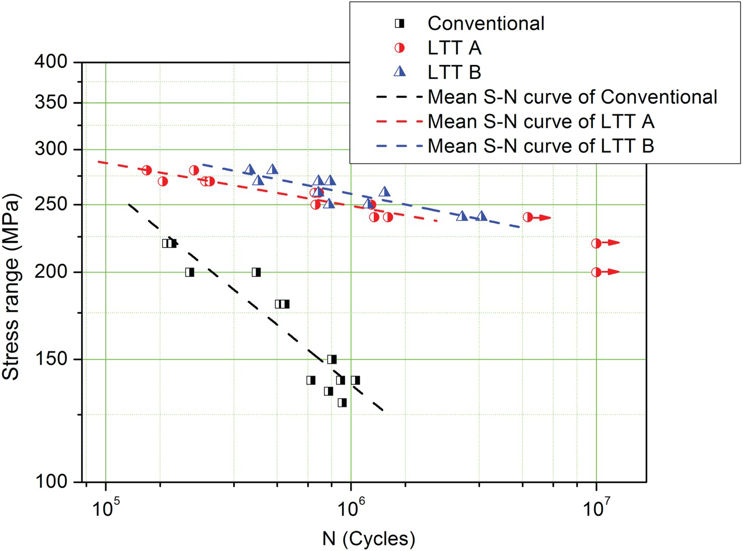
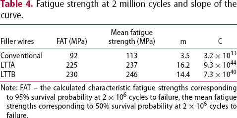
In the conventional samples, the fatigue cracks initiate at the weld toe and propagate through the base metal, because the geometric changes and high tensile residual stresses result in high stress concentrations at the weld toe. Cracks in most of the LTT samples also initiate at the weld toe and propagate through the base metal (Figure 3(a)). The exceptions include one LTTA sample and two LTTB samples, for which the fatigue cracks initiate at the weld root (Figure 3(b)). On the one hand, the LTT fillers can reduce the tensile residual stress or even produce the compressive residual stress at the weld toe. On the other hand, a large gap and inclusions can be observed at the weld root (Figure 3(b)), which cause the degree of the stress concentrations to increase. Therefore, the crack initiation sites in some of the LTT samples are transferred from the weld toe to the weld root.
Fatigue crack initiation sites for the welded joints produced using the LTT filler wires: at the weld toe (a) and weld root (b).
Residual stresses and weld toe geometry
Figure 4 shows the longitudinal surface residual stresses at a distance of 1–10 mm from the weld toe. The measured surface residual stresses of the LTTA and LTTB weld at the distance of 1 mm from the weld toe are compressive stress, whereas the stress in the conventional welds is tensile stress. The compressive residual stress of the LTTB welds (max. value of −181 MPa) is higher than that of the LTTA welds (max. value of −108 MPa). At a distance of 2–5 mm from the weld toe, tensile residual stresses with a maximum value of approximately 248 MPa exist in the LTTA welds, while the residual stresses in the LTTB welds are in the range of −22–47 MPa. Because the phase transformation-induced volume expansion of the LTT weld metals offsets the thermal shrinkage during cooling, a compressive stress can be generated at the weld metal and within a short-range of the weld toe. However, the tensile residual stress remains at distances that far from the weld toe. The resulting compressive stress is increasing with the increase in the final volume expansion of the LTT weld metal induces the greater. The LTTB welds produced using LTT fillers with lower Ms temperature exhibit the higher compressive residual stress values, due to the dilution of base metal. Moreover, the residual stress results observed here are well consistent with the fatigue test results.
Longitudinal surface residual stresses of the LTTA, LTTB and conventional welds.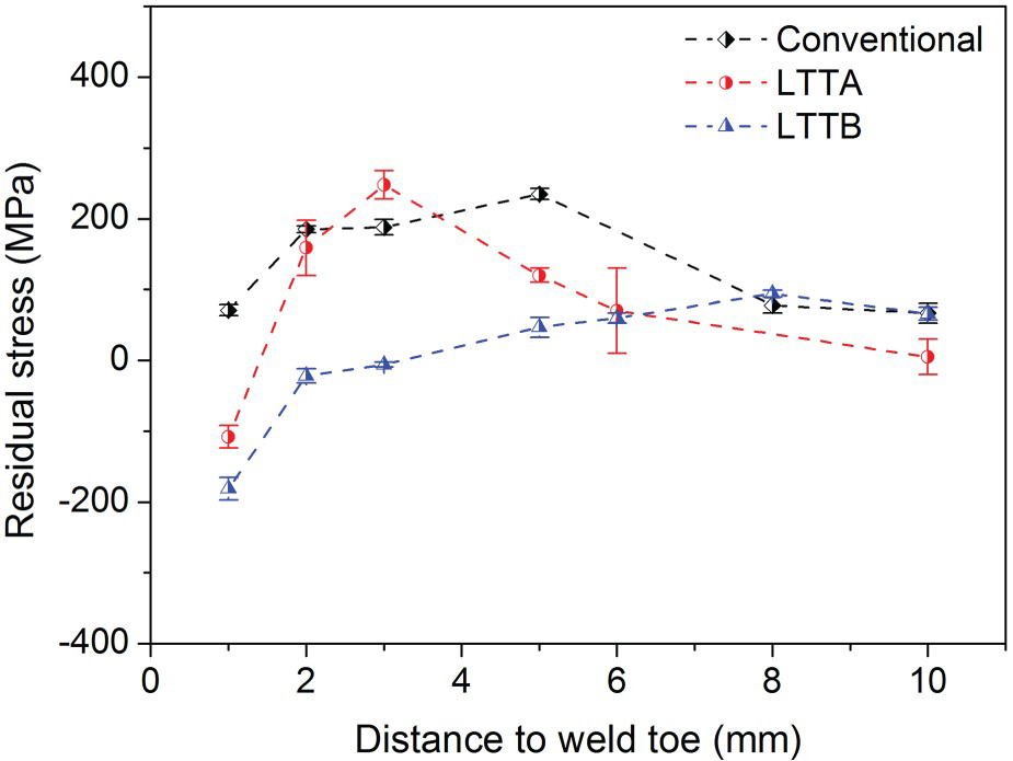
Figure 5 shows the weld toe radius and angles of the conventional, LTTA and LTTB welded joints. The average weld toe radius and angles of the conventional, LTTA and LTTB welded joints are 1.3, 1.7, 1.4 mm and 143°, 151°, 148°, respectively. The weld toe radius and angles of conventional welds are slightly lower than those of the LTT welded joint. However, there is no significant difference between the LTTA and LTTB welds. Ebrahim Harati et al. [30] investigated the relative effects of the residual stress and weld toe radius on the fatigue strength of the LTT and conventional welds. A moderate decrease in the residual stress of about 15% at the stress of 300 MPa has the same effect on fatigue strength as increasing the weld toe radius from 1.4 to 2.6 mm. In the present study, therefore, the influence of the weld toe radius on fatigue strength is not studied further.
Weld toe radius and angles of the conventional, LTTA and LTTB weld joints.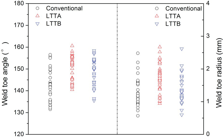
Microstructure and hardness
Based on the microstructural images (Figure 6(a,b)) and XRD results (Figure 6(c)), it can be seen that the LTTA and LTTB weld metals are composed of a single martensite phase, which indicates that the martensitic transformation of the weld metals has been completed when cooling to ambient temperature.
Microstructure (a, b) and XRD patterns (c) of the weld metals of LTTA and LTTB.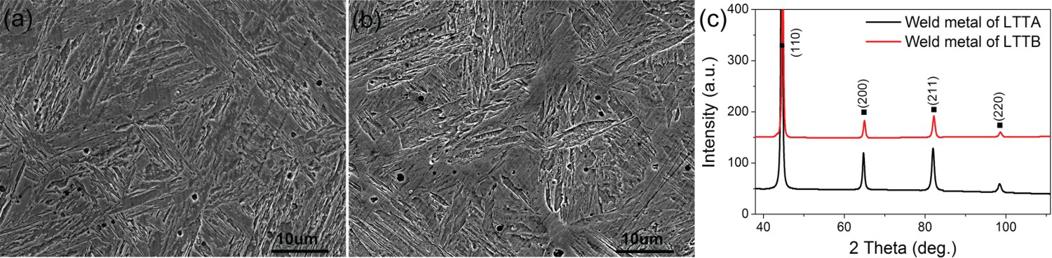
According to the hardness results shown in Figure 7(a), the average hardness of the LTTA deposited filler material and weld metal is greater than 360 HV. The average hardness of the LTTB weld metal is approximately 390 HV, while the average hardness of the LTTB deposited filler material is only 260 HV. The high hardness of the LTTB weld metal is due to the full martensite formation. To explore the inhomogeneity of the welds caused by dilution, the hardness map of the LTTB welded joint was further measured, as shown in Figure 7(b,c). For almost all of the LTTB weld metals, the hardness is higher than 350 HV, which further confirms that almost all of the LTTB weld metal has undergone the martensitic transformation. Moreover, the high hardness of the LTTB weld metal composed of martensite also indicates that the metal has a high strength [32, 33]. Thus, the LTT filler material with low yield strength can be used for the welding of high-strength steels.
Hardness (a) of the deposited filler material and weld metal of LTTA and LTTB, macrography (b) and hardness map (c) of the LTTB welded joint.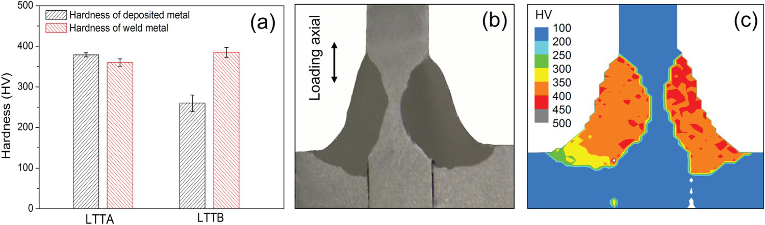
Effects of dilution on Ms, residual stress and fatigue strength
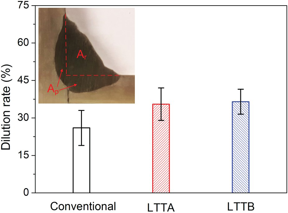
Dilution is defined as the change in chemical composition of a deposited filler material caused by mixing with either the base material or previously deposited weld material [34]. The dilution rate can be calculated according to Equation (2) [34, 35]. As shown in Figure 8, the dilution rate of LTT welds is 30–42%, which is higher than that of the conventional welds (19–33%). The higher dilution rate of the LTT welds is due to the higher heat input used for the LTT welded joints than the conventional welded joints (Table 3).
Dilution rates of the welds produced using the conventional, LTTA and LTTB filler wires.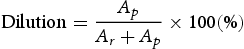
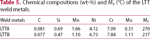
Chemical compositions (wt-%) and Ms (°C) of the LTT weld metals.
In addition, as mentioned above, the results of the microstructure and XRD analysis (Figure 6), as well as the hardness results (Figure 7), demonstrate that the martensitic transformation of the two LTT weld metals is complete when cooling to ambient temperature. The EBSD phase maps in Figure 9 further verify that there is no retained austenite in the LTTB weld metal, while the deposited filler material is composed of a martensite-retained austenite dual phase.
EBSD phase maps with IQ (image quality) of (a) the deposited filler material and (b) weld metal of LTTB.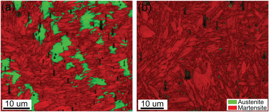
Although the martensitic transformation is complete in the two LTT weld metals when cooling to ambient temperature, the Ms temperature of the LTTA weld metal is markedly higher than 200°C (Table 5). Therefore, the martensitic transformation will be prematurely completed, and then the subsequent thermal contraction that occurs when cooling from the martensitic transformation finish (Mf) temperature to ambient temperature will counteract the effect of the volume expansion induced by the phase transformation, thereby reducing the benefit derived from the lower tensile residual stress. When the Ms temperature of the LTTB weld metal is close to 200°C, the larger final volume expansion is produced by the martensitic transformation. The phase transformation is finished at the optimum temperature, which results in maximum stress alleviation to the extent that a large compressive residual stress can be induced in the weld metal [13, 22]. Therefore, compressive residual stress near the weld toe of the LTTB welds is as great as 187 MPa, which is larger than that of the LTTA welds (Figure 4). The resulting fatigue strength is higher as well (Figure 2).
As mentioned above, the Ms temperature, residual stress and fatigue strength of LTT welds are significantly influenced by dilution. With regard to the practical aspects of applying LTT fillers, the influence of dilution should be taken into account. In the case of single-pass welds (e.g. root pass weld, single-pass fillet weld, repairing single-pass weld for the weld toe) in high-strength steel, the LTT fillers with the lower Ms temperature is a suitable choice due to the high degree of dilution of the base metal. For multi-pass welds, the use of an LTT filler with its Ms temperature close to 200°C is more useful for filling passes in which a lower dilution is desired. In addition, the dilution rate depends not only on the chemical composition of the welding fillers and the base metal but also on the welding procedure. The effect of the welding procedure on the dilution rate can be evaluated by employing the fuzzy logic model [35]. With regard to the practical application of LTT fillers, the welding procedure needs to be adapted to the welding compositions available.
Conclusion
Two different low-transformation-temperature (LTT) fillers and one conventional filler were used for producing the fillet welds. The effects of dilution on the Ms temperature, residual stresses and fatigue strength were investigated. The following conclusions can be drawn.
The use of LTT fillers with either high or low Ms temperature can significantly improve the fatigue strength of the single-pass fillet welds. Comparing with the conventional welds, the fatigue strength of the LTT fillet welds is increased by a minimum of 145%. Owing to the influence of dilution, the Cr and Ni alloying elements in LTT weld metals decrease, and as a result, the Ms temperature of LTT weld metal increases. The LTT welds produced using the LTT filler material with the lower Ms temperature (92°C) exhibit larger compressive residual stress and greater improvement of fatigue strength.
Footnotes
Disclosure statement
No potential conflict of interest was reported by the authors.
Correction Statement
This article has been republished with minor changes. These changes do not impact the academic content of the article.