
Abstract
Mg/Al dissimilar lap joint was produced by modified cold metal transfer process using Ni-based alloy wire Inconel 625 as filler metal. The characteristics of microstructure and mechanical behaviour of the joint were investigated. Microstructural analysis shows that the weld interface near Mg substrate consists of six types of areas: Mg2Al3-based area, Mg17Al12-based area, Al solid solution-based area, fusion zone-based area, Mg + Mg17Al12 eutectic area, and mixed area. With the characteristic of quasi-cleavage fracture, the tensile-shear load of the lap joint reached to 1.28 kN. The failure occurred primarily at the Mg2Al3-based area within the weld interface near Mg substrate. However, the harmful effect of the Mg2Al3 intermetallics on the strength of welded joint is limited.
Keywords
Introduction
With the continuously increasing requirement of lightweight constructions, there are a large number of Mg/Al hybrid structures required in the industrial field, especially in the automobile industry [1]. Schubert et al. [2] reported that a large potential Mg-to-Al assemblies required to be welded for mass saving of automotive applications in order to increase the fuel efficiency and reduce the greenhouse gases emission. The problem of Mg/Al dissimilar welding has to be solved. However, the application of Mg/Al dissimilar welded joint is still confined.
The challenge of Mg/Al dissimilar welding is the formation of hard-brittle intermetallic compounds (IMCs) which are detrimental to the joint strength, such as Mg2Al3 and Mg17Al12 [3]. To improve the joint strength, eliminating or reducing the Mg-Al IMCs reaction layer is essential. Numerous corresponding attempts using various welding processes were conducted with or without filler metal (or interlayer) [4-13]. The results suggest that the formation of IMCs is inevitable in the Mg/Al dissimilar welded joints. Nonetheless, two feasible approaches can be concluded to improve the joint strength: reducing Mg-Al IMCs and improving their distribution state by controlling of the welding process, or replacing Mg-Al IMCs by the IMCs with relatively low brittleness using proper filler metal.
Cold metal transfer (CMT) welding, with the excellent characteristics in terms of low energy input, high deposition rate, no spattering, and extremely stable arc [14], has become a frontier, as well as a hotspot in the welding field. Since the formation of IMCs can be decreased greatly, CMT has been widely studied on dissimilar metals welding-brazing process [15-19]. Currently, CMT is already used to join aluminium and steel for mass saving in automotive manufacturing. Owing to the low energy input and optional wire as filler metal, CMT is also a promising method to join Mg/Al dissimilar metals for vehicle body assembly. Some studies of Mg/Al dissimilar CMT welding were performed using Al-based or Mg-based wire as filler metal [20-24], but the Mg-Al IMCs interface layers were all observed, resulting in relatively low joint strength. Thus, using proper wire as filler metal couple with the appropriate control of energy input process become the key to improve CMT-welded Mg/Al dissimilar joint.
It was noted that Ni interlayer has been used for Mg/Al dissimilar welding to improve the joint strength, such as diffusion welding [25], resistance spot welding [26], friction stir welding [27], and laser welding [28, 29]. Chang et al. [27] pointed out that using a Ni foil as filler material for friction stir welded Al6061-T6/AZ31 alloy showed significant improvement in the joint strength due to the presence of less brittle Ni-based IMCs instead of Mg17Al12. Yang et al. [28] claimed that no joints were achieved without Ni interlayer in Mg/Al dissimilar laser-welding/brazing process. By inserting a Ni interlayer, the joint strength increased from 0 to 410 N with the failure at Mg/Ni interface. Based on the results of these previous studies, it can be inferred that using Ni-based wire as filler metal could be a promising candidate to improve CMT-welded Mg/Al dissimilar joint. However, the characteristics of Mg/Al dissimilar CMT welding using Ni alloy wire as filler metal are still unknown.
In the present work, a modified CMT welding process was conducted to join Mg-AZ31B/Al-6061 dissimilar alloys, and the widely used Ni-based alloy wire Inconel 625 was selected as filler metal. The weldability and macrostructure features were studied. The microstructure of the fusion zone was investigated. Subsequently, the characteristics of the interface microstructures and the fracture behaviour were emphatically analysed and discussed in order to reveal the relationship between the IMCs characteristics and the joint strength.
Materials and experimental
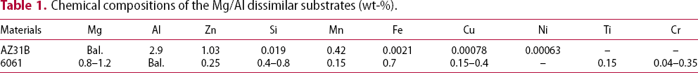
Chemical compositions of the Mg/Al dissimilar substrates (wt-%).
Chemical composition of the Ni-based welding wire (wt-%).

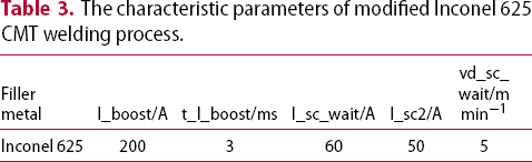
The welding configuration is demonstrated in Figure 1: the Al-6061 sheet was placed on the top of the Mg-AZ31B sheet with an overlap distance of 10 mm. A Fronius CMT Advanced 4000R arc welding system was employed with welding speed of 8 mm s−1 and shielding gas (pure argon) flow rate of 20 L min−1. To achieve effective Mg/Al dissimilar welding, based on our previous research [30], a modified Inconel 625 CMT process was conducted by control of the current and integrated wire motions using the characteristic parameters listed in Table 3. As a result, the wire feed speed was about 3.5 m min−1.
Schematic of CMT welding configuration for Mg/Al dissimilar metals using wire Inconel 625. The characteristic parameters of modified Inconel 625 CMT welding process.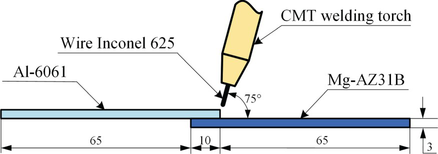
For metallography analysis, the cross-section specimen was prepared and polished. To reveal the microstructures of welded joint, the Al-6061 side and Mg-AZ31B side were etched in a solution of 5% hydrofluoric acid for 30 s and 4% nital for 180 s, respectively. Then it was observed and analysed by HITACHI SU8010 scanning electron microscope (SEM) coupled with a EDAX E1506-C2B energy dispersive spectrometer (EDS). It should be noticed that the values of EDS point analysis results are dependent on the area covered by the electron beam which is about 1 µm × 1 µm (or dependent on the area/particle size). According to AWS B4.0:2007, the tensile-shear test was conducted with a loading rate of 0.5 mm min−1 at room temperature. The test specimens with the width (length of welded seam) of 20 mm were produced by wire cutting. To minimise the bending stresses, shims were used at each end of the specimens during the testing. Subsequently, the fracture surface was observed and analysed by SEM coupled with EDS and PANalytical Empyrean X-ray diffraction (XRD).
Results and discussion
Weldability and macrostructure
For Mg/Al dissimilar CMT welding process using Ni-based wire as fill metal, the major difficulty is the formation of magnesium vapour which is detrimental to the metal transfer process. As a result, the Mg/Al dissimilar butt joint was not obtained because the directly contact between the high-temperature Ni-based droplets and low-boiling Mg substrate caused a large number of magnesium vapours. In this study, to reduce the formation of magnesium vapour, lap welding was performed. On the one hand, as Mg substrate was placed under Al substrate, the directly contact between the droplet and Mg substrate was avoided. On the other hand, as characteristic parameters of the CMT welding process was modified, the temperatures of both droplet and substrate were reduced (according to our previous research [30], slow wire feed speed coupled with low burn phase current will cool the droplet and substrate during the burn phase of the CMT welding process).
As a result, Mg-AZ31B and Al-6061 sheets were effectively welded by the modified Inconel 625 CMT process. The macrostructures of welded joint are showed in Figure 2. On the top surface, some spatters were found due to the vapour pressure of magnesium hindered the droplets transfer during the welding process, as showed in Figure 2(a). On the cross-section, since the most of energy input was used to heat Al substrate which was on the top of Mg substrate, a lot of Al substrate was melted and flowed into the fusion zone (FZ) while a few Mg substrate was melted, as showed in Figure 2(b). Moreover, it can be observed that some porosities formed near Mg substrate.
Macrostructures of the CMT-welded Mg/Al dissimilar joint using wire Inconel 625: (a) top view, and (b) cross-section.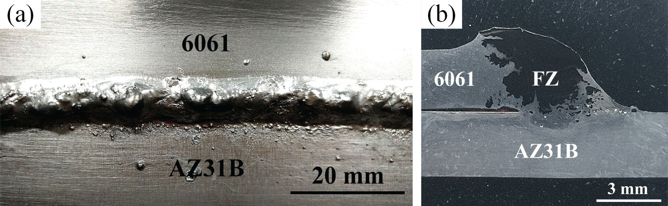
Microstructure of fusion zone
The microstructure of fusion zone was basically uniform due to the rapid flow and diffusion of Al melts (6061 substrate) in the high-temperature weld pool (mainly consist of molten wire Inconel 625). Figure 3 shows the microstructures in the centre of fusion zone, and the EDS analysis results are listed in Table 4. Since a lot of Al substrate was melted, the chemical composition of fusion zone with high Al content of about 28.5 at.-% (while Mg content is only 1.6 at.-%) clearly differs from that of Inconel 625 alloy. As a result, the fusion zone is mainly characterised with grey AlNi-based equiaxed grain [31], and there are lots of white Ni-rich and Cr-rich phases [32] in the grain boundaries. In addition, the microhardness of the fusion zone is 361.7 HV, which is much higher than that of Inconel 625 alloy (260 HV) [33].
Microstructures of the fusion zone: (a) centre of fusion zone, and (b) zone A shown in Figure 3(a). EDS analysis results of the various zones shown in Figure 3 (at.-%).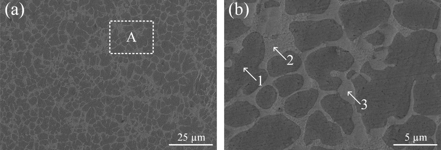
Interface microstructure near Al substrate
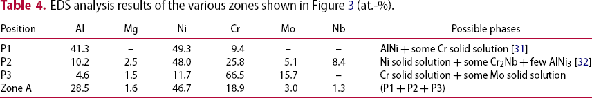
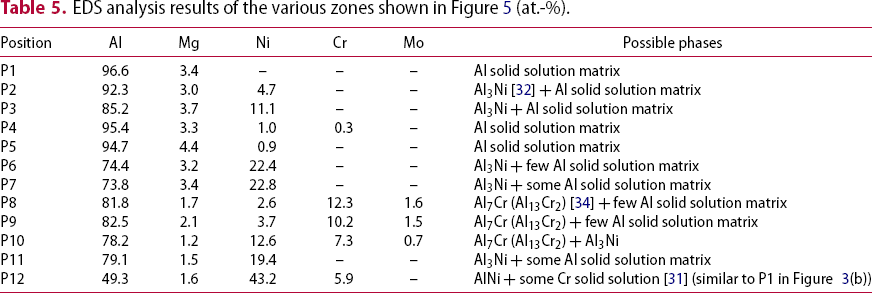
Figure 4 shows the EDS map analysis results of the weld interface near Al substrate. Since the melted Al substrate flowed and diffused rapidly in the high-temperature weld pool during the welding process, there is a clearly boundary between the Al substrate and fusion zone. However, the high concentration gradients caused the Ni and Cr atoms (two major elements of wire Inconel 625) to diffuse from fusion zone into Al substrate at the weld boundary, and the Ni atoms would diffuse further than Cr atoms due to the high content of Ni elements of fusion zone. Subsequently, the Al-riched Al-Ni and Al-Cr phases, which has the relatively low melting point, can be formed within the Al substrate close to the weld boundary. According to the previous studies [32, 34] and EDS analysis results shown in Table 5, the microstructures of the weld interface near Al substrate shown in Figure 5 were analysed. Within the Al substrate near weld boundary, there are some reticular Al3Ni intergranular precipitates in the grain boundaries of Al solid solution, as shown in Figure 5(b). Within the Al substrate next to weld boundary, there are lots of massive Al3Ni phases and granular Al7Cr (Al13Cr2) phases in the Al solid solution matrix, as shown in Figure 5(c).
EDS map analysis results of the weld interface near Al substrate. Microstructures of the weld interface near Al substrate: (a) zone A shown in Figure 4, (b) zone B shown in (a), and (c) zone C shown in (a). EDS analysis results of the various zones shown in Figure 5 (at.-%).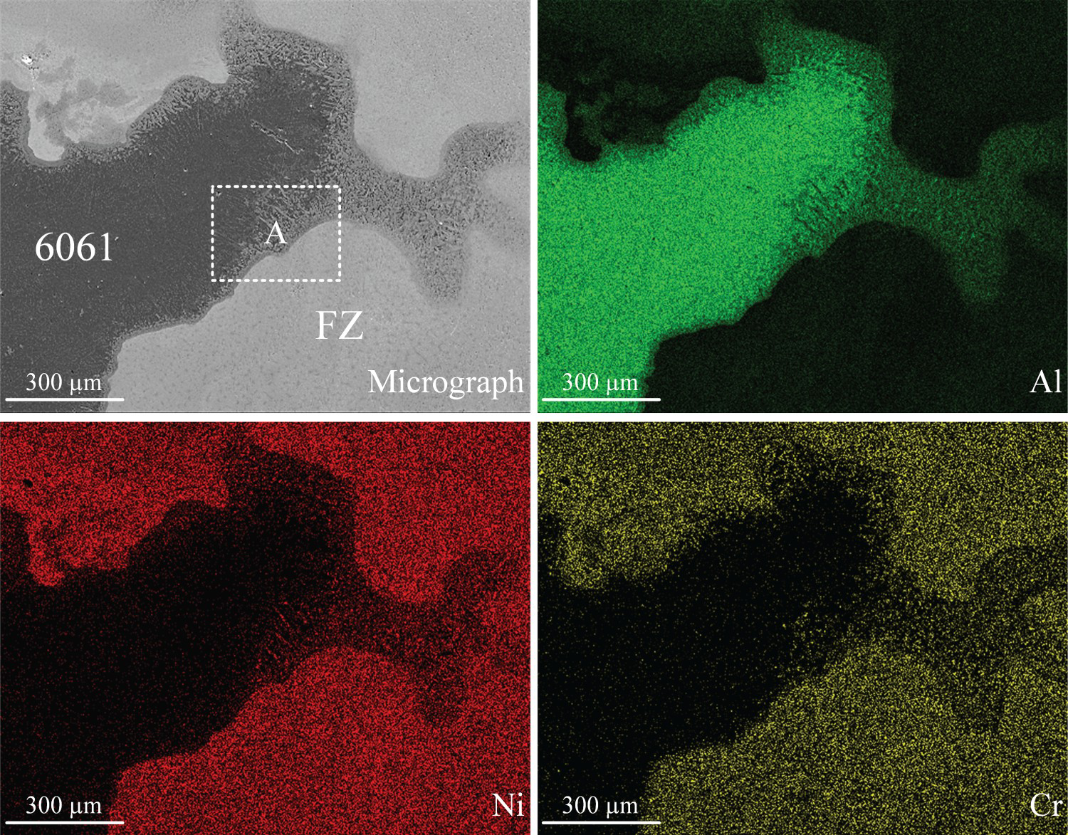
Interface microstructure near Mg substrate
Since some of the melted Al substrate flowed to the bottom of the fusion zone, the hard-brittle Mg-Al IMCs would form near Mg substrate. Figure 6 shows the EDS map analysis results of the weld interface near Mg substrate, which can confirm the enrichment of element Al at the weld interface. However, the distributions of the main elements within the weld interface are all uneven, indicating that there are several different types of areas with different microstructures formed within the weld interface near Mg substrate, as shown in Figure 6(b).
EDS map analysis results of the weld interface near Mg substrate: (a) micrograph, (b) phase map, and (c) distribution of elements.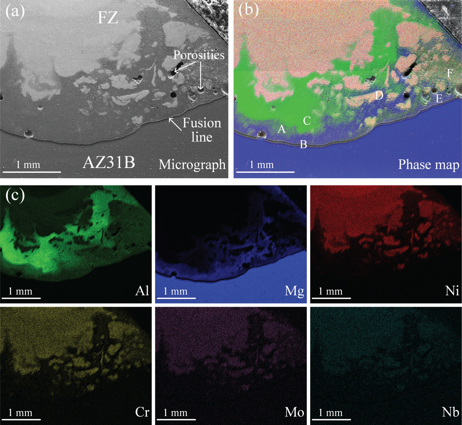
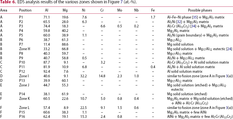
Figure 7 shows the microstructures of the different areas within the weld interface near Mg substrate. For Mg-Al IMCs, Wang et al. [24] suggested that the relatively wide ranges of the composition of Mg2Al3, Mg17Al12, and Mg17Al12 + α-Mg solid solution eutectic were about 37–45, 45–60, and 60–70 at.-% Mg, respectively. According to the previous studies [24, 32, 34, 35] concerning the related binary/ternary phase diagram, EDS point analysis of the various zones were conducted to investigate the microstructure characteristics. The results are listed in Table 6. It can be concluded that the weld interface near Mg substrate mainly consist of six types of areas: Mg2Al3-based area mainly composed of Mg2Al3 matrix, Al3Ni phase, Al7Cr (Al13Cr2) phase, and Al–Fe-Ni phase, as shown in Figure 7(a,b); Mg17Al12-based area mainly composed of Mg17Al12 matrix and Al3Ni phase, as shown in Figure 7(c,d); Al solid solution-based area near the fusion zone, which mainly composed of Al solid solution matrix, Al3Ni phase, and Al7Cr (Al13Cr2) phase, as shown in Figure 7(e); fusion zone-based area with the similar microstructure and composition compared to fusion zone, as shown in Figure 7(f); Mg + Mg17Al12 eutectic area near the fusion line, which composed of Mg + Mg17Al12 eutectic matrix and Mg solid solution, as shown in Figure 7(g); and mixed area mainly composed of Mg2Al3 matrix, Mg solid solution, AlNi phase, and Al7Cr (Al13Cr2) phase, as shown in Figure 7(h). As shown in Figure 7(b), for Mg2Al3-based area, the stripy Al–Fe-Ni phases [35] denoted by point 1, Al3Ni particles [32] (primary precipitated) denoted by point 2, and Al7Cr (Al13Cr2) particles [34] denoted by point 3 are observed in the Mg2Al3 matrix. It should be noticed that some tiny reticular Al3Ni phases [32] (secondary precipitated) denoted by point 5 were formed at the grain boundaries of Mg2Al3 matrix, which would reinforce the hard-brittle Mg2Al3-based area. Moreover, as shown in Figure 7(b), for Mg17Al12-based area, some tiny long strip Al3Ni phases [32] are also observed at the grain boundaries of Mg17Al12 matrix.
Microstructures of the weld interface near Mg substrate: (a) area A shown in Figure 6(b), (b) zone F shown in (a), (c) area B shown in Figure 6(b), (d) zone G shown in (c), (e) area C shown in Figure 6(b), (f) area D shown in Figure 6(b), (g) area E shown in Figure 6(b), and (h) area F shown in Figure 6(b). EDS analysis results of the various zones shown in Figure 7 (at.-%).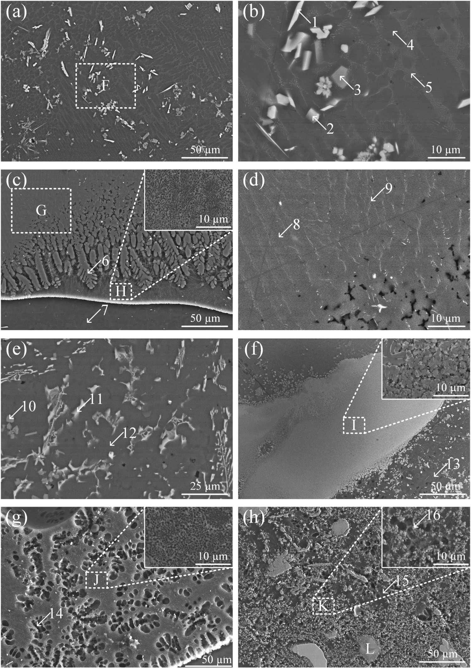
Fracture characteristic analysis
Figure 8 shows the tensile-shear test results of the welded joint. The average tensile-shear load of the CMT-welded Mg/Al dissimilar lap joint using wire Inconel 625 as filler metal was 1.28 kN (1.321, 1.252, and 1.266 kN). There was no obvious phenomenon of necking and plastic deformation in the fracture area. All specimens fractured at the weld interface near Mg substrate due to the formation of hard-brittle Mg-Al IMCs. However, the tensile-shear load is much higher than that of the CMT-welded Mg/Al dissimilar lap joint using Al-based wire ER4047 (0.38 and 0.93 kN) [22], indicating that using Ni-based wire is better than Al-based wire for Mg/Al dissimilar CMT welding process. Moreover, as using Ni interlayer for filler metal, the CMT-welded lap joint in this study is also much stronger than the laser-welded/brazed lap joint (0.41 ± 0.025 kN) [28].
Tensile-shear test results of the CMT-welded Mg/Al dissimilar joint: (a) fractured specimen, and (b) load-displacement curve.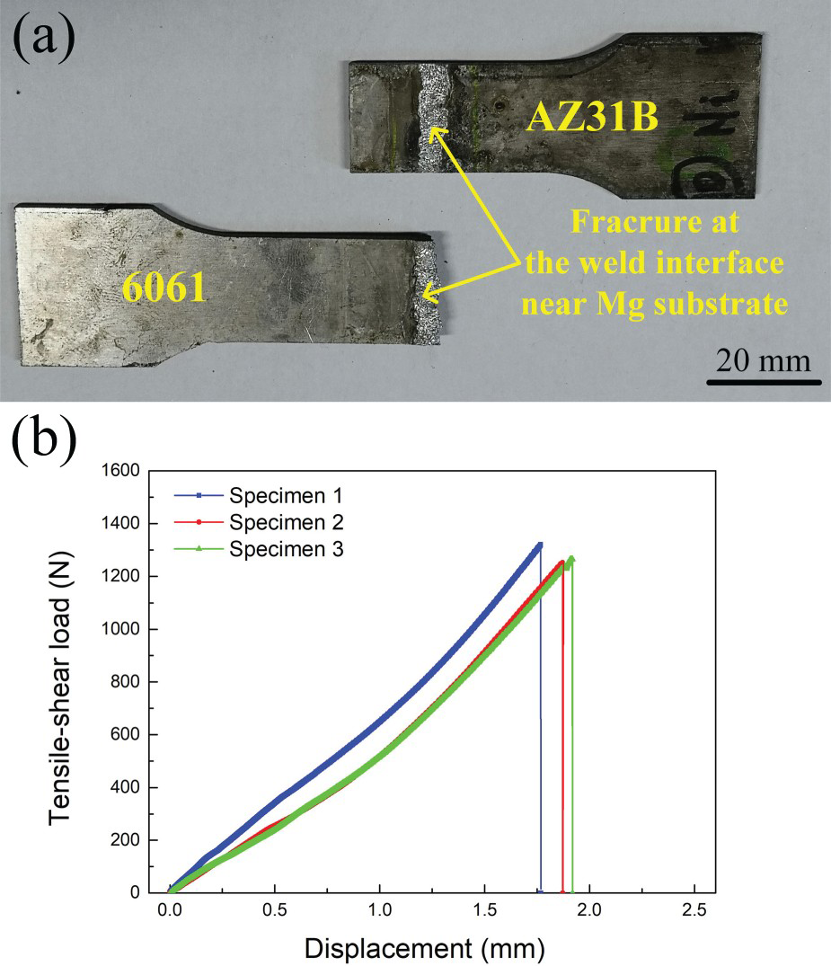
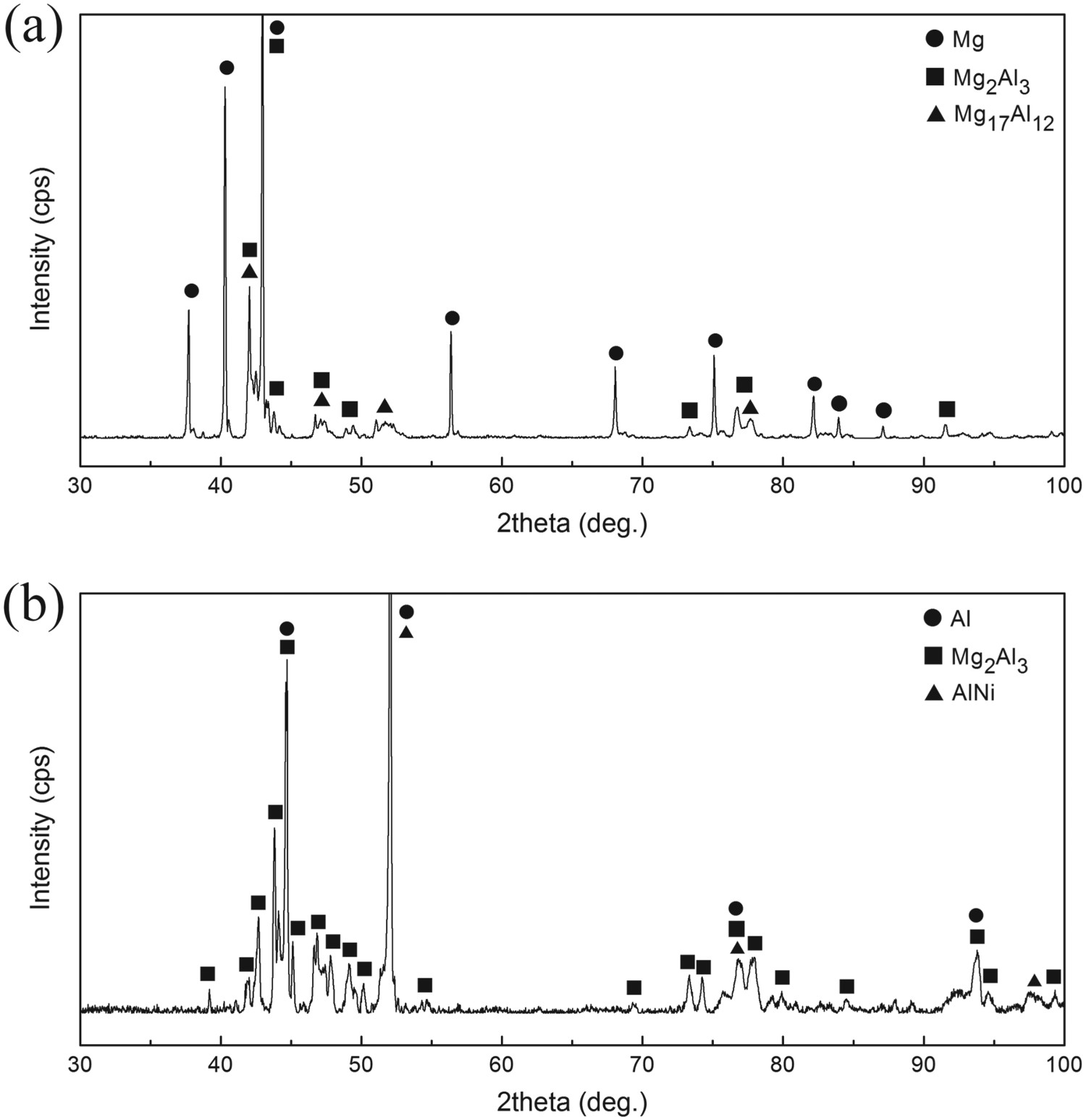
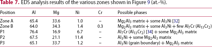
As shown in Figure 9, the fracture surface of welded joint was characterised. The uneven river pattern with plenty of tearing ridges can be seen on the fracture surface, which confirm the quasi-cleavage fracture. Furthermore, there are also some particles (point 1 and 2) on fracture surface and tiny reticular phases (point 3) at the edges of tearing ridges, which would hinder the fracture propagation. As listed in Table 7, EDS analysis results suggest that the matrix on fracture surface is Mg2Al3, the particles on fracture surface are Al3Ni [32] and Al7Cr (Al13Cr2) [34], and the tiny reticular phases at the edges of tearing ridges also is Al3Ni [32]. These results are consistent with the microstructure characteristics of the Mg2Al3-based area within the weld interface near Mg substrate, as shown in Figure 7(a,b). Figure 10 shows the XRD patterns of the constitutive phases on the fracture surfaces. As shown, peaks of Mg solid solution (dominant phase in the Mg substrate and Mg + Mg17Al12 eutectic areas near the fusion line), Mg2Al3 (dominant phase in the Mg2Al3-based areas), and Mg17Al12 (dominant phase in the Mg17Al12-based areas and Mg + Mg17Al12 eutectic areas near the fusion line) are presented at the Mg substrate side, and peaks of Al solid solution (dominant phase in the Al solid solution-based areas near the fusion zone), Mg2Al3 (dominant phase in the Mg2Al3-based areas), and AlNi (dominant phase in the fusion zone) are presented at the fusion zone side. Since the X-ray can penetrate the fracture surface (about 30 µm deep), referring to the interface microstructure near Mg substrate, the XRD analysis results suggest that the fracture mainly occurred from the location in the middle part of weld interface where the Mg2Al3-based areas are. Based on the above results, it can be concluded that the quasi-cleavage fracture of CMT-welded Mg/Al dissimilar lap joint using wire Inconel 625 occurred primarily at the Mg2Al3-based areas within the weld interface near Mg substrate.
Fracture surface of the CMT-welded Mg/Al dissimilar joint. XRD patterns of the constitutive phases on the fracture surfaces: (a) Mg substrate side, and (b) fusion zone side. EDS analysis results of the various zones shown in Figure 9 (at.-%).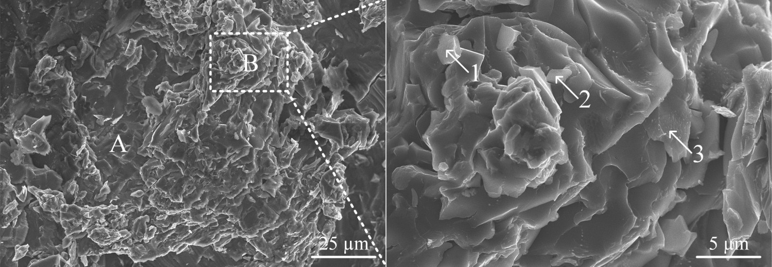
Microstructure-strength relationship
The strength of CMT-welded Mg/Al dissimilar joint using wire Inconel 625 as filler metal was not as high as expected. This is because the formation of hard-brittle Mg-Al IMCs was not completely prevented. For weld interface near Al substrate, some Al3Ni and Al7Cr (Al13Cr2) phases formed in the Al solid solution matrix, which makes a slight effect on the interface strength. For weld interface near Mg substrate, the hard-brittle Mg-Al IMCs formed, which are detrimental to the interface strength, such as Mg2Al3-based areas, Mg17Al12-based areas, and Mg + Mg17Al12 eutectic areas. Moreover, the previous study under the compound casting process [36] shows that the three Mg-Al intermetallics with strength form high to low are Mg + Mg17Al12 eutectic, Mg17Al12, and Mg2Al3. Therefore, the CMT-welded Mg/Al dissimilar lap joint using wire Inconel 625 fractured primarily within the Mg2Al3-based area where is the weakest area within the weld interface near Mg substrate. However, the result of tensile-shear test shows that the harmful effect of the Mg2Al3 intermetallics on the strength of welded joint is limited. First, the distribution of Mg2Al3-based areas is uneven, avoiding the formation of continuous Mg2Al3 layer along the weld boundary [3]. Second, the precipitated particles such as Al–Fe-Ni phase, Al3Ni, and Al7Cr (Al13Cr2) formed in the Mg2Al3 matrix, reducing the brittleness of Mg2Al3 matrix. Thirdly, the tiny reticular Al3Ni phases formed at the grain boundaries of Mg2Al3 matrix, reinforcing the strength of Mg2Al3-based area. Thus, the lap joint using Ni-based wire as filler metal in this study, with tensile-shear load of 1.28 kN, is much stronger than that using Al-based wire as filler metal [21, 22]. For further study, in order to improve the CMT-welded Mg/Al dissimilar joint using Ni-based wire, preventing the contact of substrates thereby eliminating the Mg-Al IMCs is essential.
Conclusions
Mg-AZ31B/Al-6061 dissimilar lap joint was effectively produced by modified CMT welding process using Ni-based alloy wire Inconel 625 as filler metal. To analyse the characteristics of interface microstructures and fracture behaviour, the following conclusions can be drawn.
There was a clearly boundary between Al substrate and fusion zone. Within the Al substrate next to weld boundary, lots of massive Al3Ni phases and granular Al7Cr (Al13Cr2) phases formed in the Al solid solution matrix. Within the Al substrate near weld boundary, some reticular Al3Ni intergranular precipitates formed in the grain boundaries of Al solid solution. Owing to the uneven distributions of the elements between Mg substrate and fusion zone, there were six types of areas with different microstructures formed within the weld interface near Mg substrate: Mg2Al3-based area, Mg17Al12-based area, Al solid solution-based area, fusion zone-based area, Mg + Mg17Al12 eutectic area, and mixed area. With the characteristic of quasi-cleavage fracture, the tensile-shear load of lap joint reached to 1.28 kN. The failure occurred primarily at the Mg2Al3-based areas within the weld interface near Mg substrate. However, the harmful effect of the Mg2Al3 intermetallics on the strength of welded joint is limited due to the uneven distribution of Mg2Al3-based areas, the formation of Al-riched precipitated particles in Mg2Al3 matrix, and the formation of tiny reticular Al3Ni phases formed at grain boundaries of Mg2Al3 matrix. Using Ni-based wire is better than Al-based wire for Mg/Al dissimilar CMT welding process. To improve the joint, preventing the contact of substrates thereby eliminating the Mg-Al intermetallics is essential.
Footnotes
Disclosure statement
No potential conflict of interest was reported by the authors.