
Abstract
Resistance spot weldability of martensitic stainless steels is impaired by the formation of brittle martensite in the fusion zone (FZ). In this paper, in situ rapid tempering via applying a second pulse current after a first melting/solidification pulse during resistance spot welding of AISI 420 martensitic stainless steel sheets was used as a pathway to enhance the toughness of the FZ. By using proper second pulse conditions, the FZ with reduced hardness can be generated which is featured by a decomposed martensitic structure with nano-sized carbide precipitations. The improved toughness as a consequence of this modified microstructure resulted in remarkable enhancement of the peak load and energy absorption of the spot welds compared to the single-pulse welds.
Keywords
Introduction
The hot-stamping process which is enabled to produce ultra-high strength steels is a pivotal strategy to address the need for weight-reduced automobiles with improved fuel consumption as well as enhanced crash safety [1]. Recently, martensitic stainless steels (MSS) can be regarded as a possible alternative solution to existing C–Mn boron hot-stamp steels [2, 3]. However, weldability which demonstrates the in-service reliability of a welded structure is the critical challenge for the widespread application of MSS due to the formation of hard and brittle martensite in the fusion zone (FZ) and heat-affected zone (HAZ) [4, 5]. Therefore, understanding the behaviour of MSS during resistance spot welding (RSW), as the critical manufacturing technology in the automotive industry, is indispensable for their utilisation in the automotive body-in-white as alternative hot-press steel.
Previous works have demonstrated that MSS resistance spot welds are susceptible to quasi-cleavage interfacial failure (IF) with weak energy absorption capability due to the formation of hard and brittle carbon and chromium-rich martensite in the FZ [6-9]. It has been identified that the mechanical properties of the of martensitic stainless steel RSWs during both tensile-shear (TS) and cross-tension (CT) loading are dictated by the low fracture toughness of the FZ which encourages failure via crack propagation through the FZ [7, 10]. Therefore, improving the mechanical properties of MSS RSWs should reply to improving the fracture toughness of the weld. Recently, Aghajani and Pouranvari [11] proposed a new approach to enhance strength/toughness of the martensitic stainless steel resistance spot welds based on the alteration of the FZ composition/microstructure via introducing a nickel interlayer. It was shown that the formation of a tough predominately austenitic microstructure in the FZ provides a pathway to obtain a pullout failure with significantly enhanced energy absorption. Despite the potential of this technique to a remarkable improvement of the weldability of martensitic stainless steel resistance spot welds, using a nickel-interlayer is not a cost-effective approach.
Tempering is a traditional approach to improve the toughness of the brittle martensite [12]. Tempering can be applied during the RSW process as a second pulse aiming at heating a martensitic structure below A1 temperature [13]. It is proven that in situ tempering of the weld during RSW can alleviate the problem of high sensitivity to the IF of the resistance spot welds of the advanced high strength steels thorough reduction of hardness in the FZ [14-19]. Therefore, this work aims at applying this approach to martensitic stainless steel resistance spot welds. A second pulse current was applied after the first melting/solidification pulse. The effects of second pulse duration on the microstructure and mechanical properties AISI420 resistance spot welds are studied. The results showed that rapid in situ tempering could provide a cost-effective pathway to remarkably enhance the load-bearing capacity and energy absorption capability of martensitic resistance spot welds.
Experimental methods
In the present study, a 1.5 mm thick annealed AISI420 (Fe–0.34C–0.55Mn–0.30Si–12.9Cr–0.09Ni–0.03Cu–0.06 V) martensitic stainless steel was used as the BM. RSW was performed using a PLC controlled, 120 kVA/ 50 HZ alternative current pedestal type RSW machine. Welding was conducted using a 45-deg truncated cone Resistance Welding Manufacturing Alliance Class 2 electrode with 8-mm face diameter. The electrode force during welding was 5 kN. Two distinguish welding strategies were employed in this work:
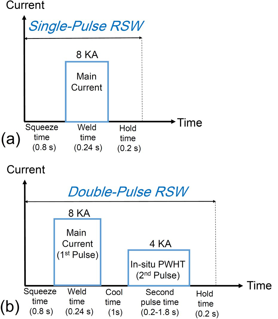
Single pulse welding: This welding strategy enabled creation a spot weld with weld FZ size larger than 4t0.5 (i.e. conventional weld sizing recommendation for resistance spot welds). Figure 1(a) displays the schematic of single pulse welding strategy. Double-pulse welding: This two-pulse welding strategy was carried out to study the potential of the second pulse to modify the FZ microstructure and improve the mechanical properties. Figure 1(b) presents the schematic of two pulse welding strategy. Five different post weld second pulse times were performed after the first melting/solidification pulse. (a) single-pulse welding schedule and (b) double-pulse welding schedule used in this study for welding of AISI420 martensitic stainless steel sheets.
The mechanical properties of the resistance spot welds made using single and double pulse welding strategies were examined through the tensile-shear (TS) and CT tests. The dimensions of both TS and CT were 25mm×100 mm. The crosshead speed for TS and CT test were 10 and 2 mm min−1, respectively. Peak load, energy absorption, and failure mode were used to describe weld mechanical performance.
Weld microstructures and macrostructures were examined using both optical microscopy (OM) and field emission scanning electron microscopy (FESEM). Villela etchant was used to reveal the weld microstructure. Vickers microhardness testing was practiced to evaluate the hardness values of the welds with an applied load of 200 g and a force holding time of 15 s.
Results and discussion
Microstructure-property relationship in single pulse MSS welds
Figure 2(a,b) shows the overall macrostructure/hardness profile of the AISI420 MSS steel welds after single-pulse RSW indicating microstructure/hardness gradient in the weld zone. The AISI420 MSS exhibited hardening in the HAZ and FZ due to non-equilibrium phase transformation during welding. The details of phase transformation during RSW of AISI420 steel are discussed elsewhere [6, 7]. According to optical micrograph in Figure 2(c) and FESEM micrographs in Figure 2(d,e) the FZ microstructure consisted of predominately martensitic structure with some δ-ferrite along the solidification grain and sub-grain boundaries with an average hardness of 570 HV which is significantly higher than that of BM (180 HV). The brittleness of the FZ led to propagation a crack through the FZ during metallographic sample preparation (Figure 2(c)).
(a) macrostructure,(b) hardness profile (c) optical micrograph showing FZ microstructure, the crack is produced during sectioning of the metallographic sample preparation, (d,e) FESEM micrographs showing microstcuture of the FZ in the single-pulse resistance spot welded AISI420 maretnsitic stainless steels.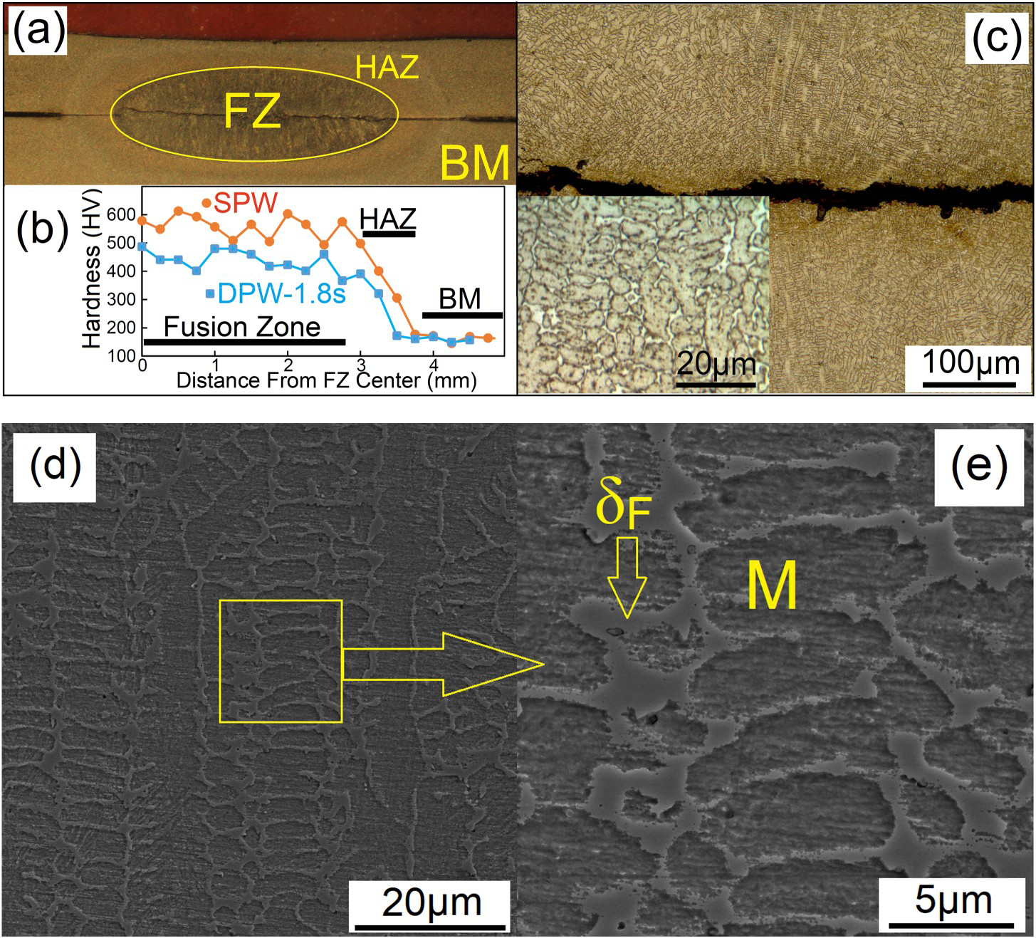
Single-pulse resistance spot welded MSS420 sheets were failed in IF mode during both TS and CT tests. According to Figure 3(a,b), a cleavage surface was observed in MSS welds failed during both TS and CT tests which indicates a low-energy failure. The peak loads of single pulse RSW in TS and CT were 6.7 and 1.3 kN, respectively. Moreover, they exhibited 2.6 and 0.6 J energy absorption during TS and CT loading conditions, respectively. The weak load bearing capacity and energy absorption capability of MSS420 welds can be attributed to the low fracture toughness of the FZ. Therefore, to utilise the potential of MSS in automotive industry, there is a need to find a pathway to improve their weld mechanical performance. Pouranvari [10] showed that unlike to most of the automotive steels, the IF of AISI420 MSS spot welds during the tensile-shear test is controlled by the fracture toughness of the FZ. It is also well documented that the IF of the spot welds during cross-tension loading is governed by FZ fracture toughness [14]. Therefore, in order to improve the mechanical properties of the MSS spot welds, there is a need to develop a proper pathway to improve the toughness of the FZ. This can be achieved by in-process quench and tempering of the weld nugget using a second current pulse.
FESEM fracture surface of the single pulse martensitic stainless steel resistance spot welds after (a) the tensile-shear testing and (b) the CT testing at two magnifications.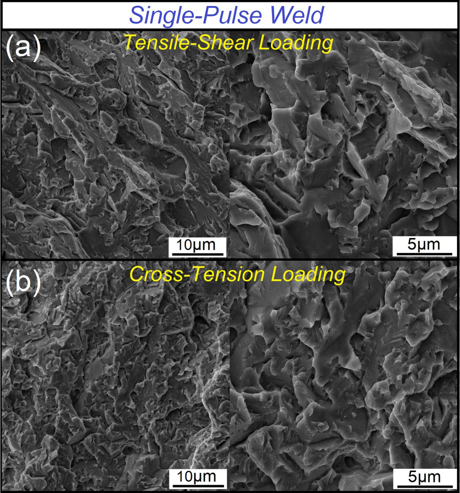
Microstructure-property relationship in double-pulse MSS welds
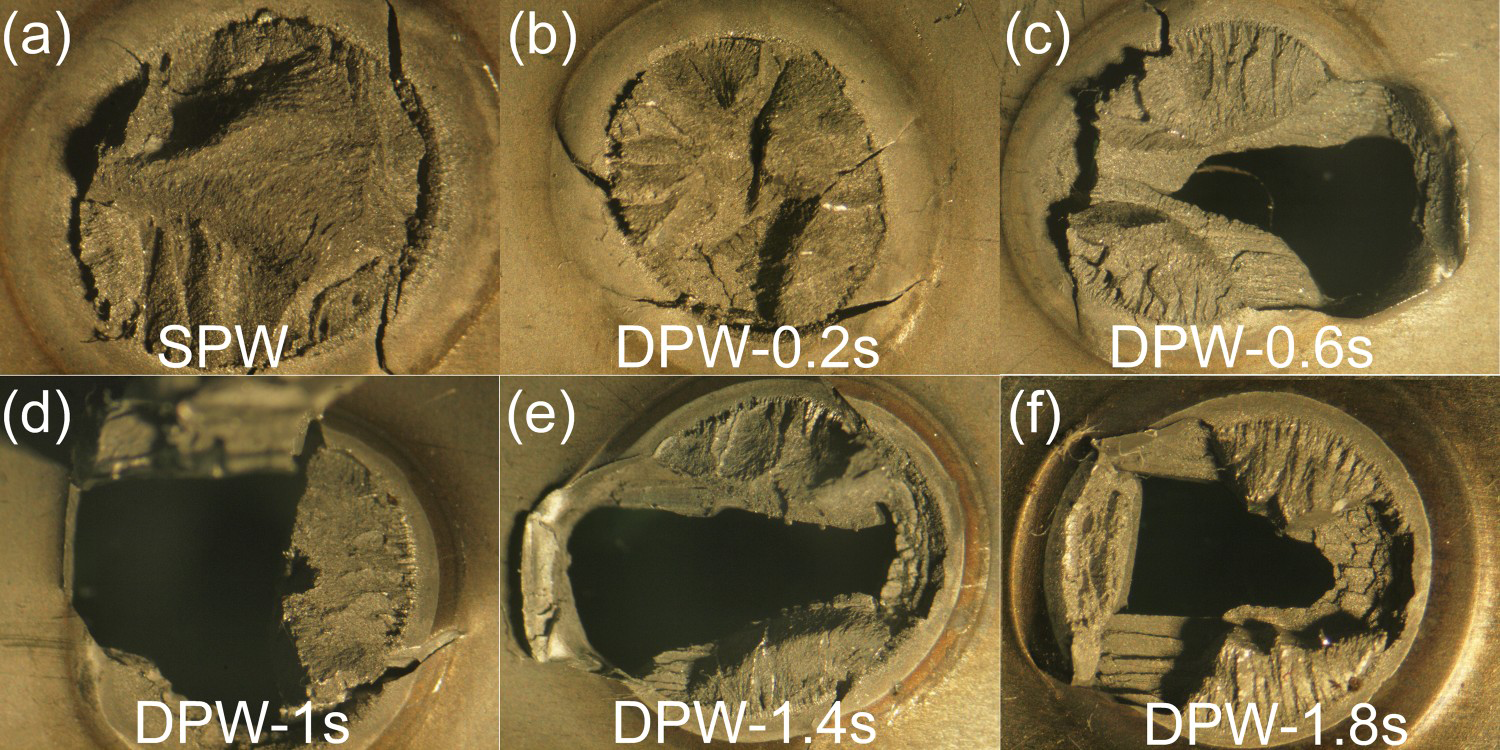
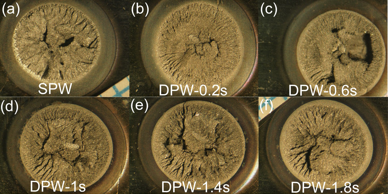
Figure 4(a,b) illustrates the impact of the second pulse on the weld mechanical properties indicating that both load-bearing capacity and energy absorption capability during both TS and CT loading conditions were improved upon applying second pulse currents. According to Figure 4(a), at the best post weld heat treatment condition (i.e. when the second pulse time is 1.4 s) the peak load and failure energy during TS loading were improved by about 77% and 240%, respectively. Moreover, according to Figure 4(b), at the best post weld heat treatment condition, the peak load and failure energy during CT loading were improved by about 102% and 1030%, respectively. Figure 5 and Figure 6 show the failure mode of single and double pulse resistance spot welded MSS420 during TS and CT loading conditions, respectively. As can be seen in Figure 5, increasing second pulse time beyond 0.2 s changes the failure mode from full interfacial mode to partial interfacial mode. However, the application of the second pulse did not change the failure mode of the MSS420 spot welds during CT loading (Figure 6). All double-pulse welds failed in full interfacial mode during the CT test. Despite the fact that no full pullout mode was obtained in double-pulse RSWs, they exhibited improved mechanical properties compared to the single-pulse welds.
Effect of second pulse time on the mechanical properties (peak load and energy absorption) of MSS420 resistance spot welds (a) the tensile-shear loading and (b) CT loading. TSS: Tensile-shear strength, CTS: Cross-tension strength. Failure mode of MSS420 resistance spot welds during tensile-shear loading: (a) single-pulse weld, (b–f) double pulse welds with second pulse times between 0.2 s to 1.8 s. Failure mode of MSS420 resistance spot welds during CT loading: (a) single-pulse weld, (b–f) double pulse welds with second pulse times between 0.2 s to 1.8 s.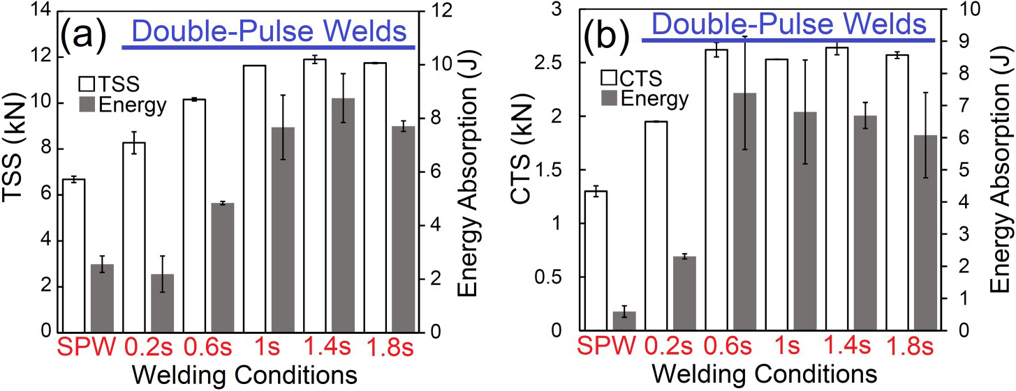
To elucidate the enhancement of peak load and energy absorption of MSS RSWs after in situ post weld heat treatment, the effect of second pulse on the both weld physical characteristics (i.e. FZ size) and weld metallurgical features are examined.
Effect of second pulse time on the FZ size
The FZ size is the key geometrical factor affecting the mechanical performance of the resistance spot welds [20, 21]. Figure 7 demonstrates the effect of second pulse time on the FZ size indicating that the FZ size for the double pulse welds is almost identical to the single pulse weld. Therefore, the improved mechanical properties of the welds after second pulse cannot be attributed to the weld geometry.
Effect of second pulse time on the FZ size of the MSS420 resistance spot welds.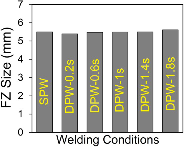
Effect of second pulse time on the FZ microstructure/hardness
Figure 8 displays the influence of the second pulse time on the FZ hardness. As can be seen, applying a second pulse with a duration of 0.2 s did not affect the hardness of the FZ. Figure 9(a,b) shows the microstructure of the FZ in 0.2 s double-pulse weld indicating that the FZ microstructure is similar to single phase RSW. No martensite decomposition and carbide precipitation were detected in this sample.
Effect of second pulse time on the average hardness of the FZ of the MSS420 resistance spot welds (The hardness values are the average of at least ten measurements in the FZ). Effect of second pulse time on the microstructure of the FZ of the MSS420 resistance spot welds: (a,b) double pulse weld with second pulse time of 0.2 s, (c,d) double pulse weld with second pulse time of 0.6 s, (e,f) double pulse weld with second pulse time of 1.8 s.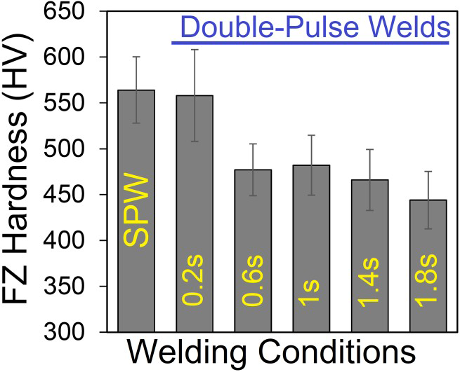

Increasing the second pulse time to 0.6–1.8 s, the FZ hardness was reduced by 80–120 HV (see Figure 8). Figure 9(c–f) shows the OM micrographs of the FZ after 0.6 and 1.8 s second pulses time, respectively, indicating the presence of dark and light-etching regions. Figure 10 shows FESEM micrographs of the FZ in DPW with 1.8 s second pulse time. Figure 10(a) shows a low magnification FESEM micrograph of the FZ showing the corresponding regions with the dark and light-etching region in OM micrographs. However, higher magnification examination (Figure 10(b–d)) of the dark-etching regions revealed that the martensite decomposition and precipitation of nano-sized carbide particles have occurred. Despite the fact these precipitates are in nano-scale, the EDS-FESEM analysis revealed (not shown here) that they are Cr-rich particle. It is shown previously that the tempering process of AISI420 martensitic stainless steel is accompanied by precipitation of Cr-rich M23C6 carbides [12, 22]. Therefore, it has been concluded that martensite tempering has occurred in the dark-etching regions. No indication of martensite tempering was detected in the light-etching regions. Therefore, they are un-tempered zones in the FZ. According to Figure 9, increasing the second pulse time from 0.6 s to 1.8 s increases the volume fraction of dark-etching region which confirms that the tempering process is enhanced by increasing the temper pulse time.
FESEM micrographs showing FZ microstructure double-pulse MSS420 resistance spot weld with 1.8 s second pulse time (a,b) the presence of tempered and un-tampered zones in the FZ, (c) martensite decomposition in the tempered zone and (d) nano-sized carbide precipitation in the FZ.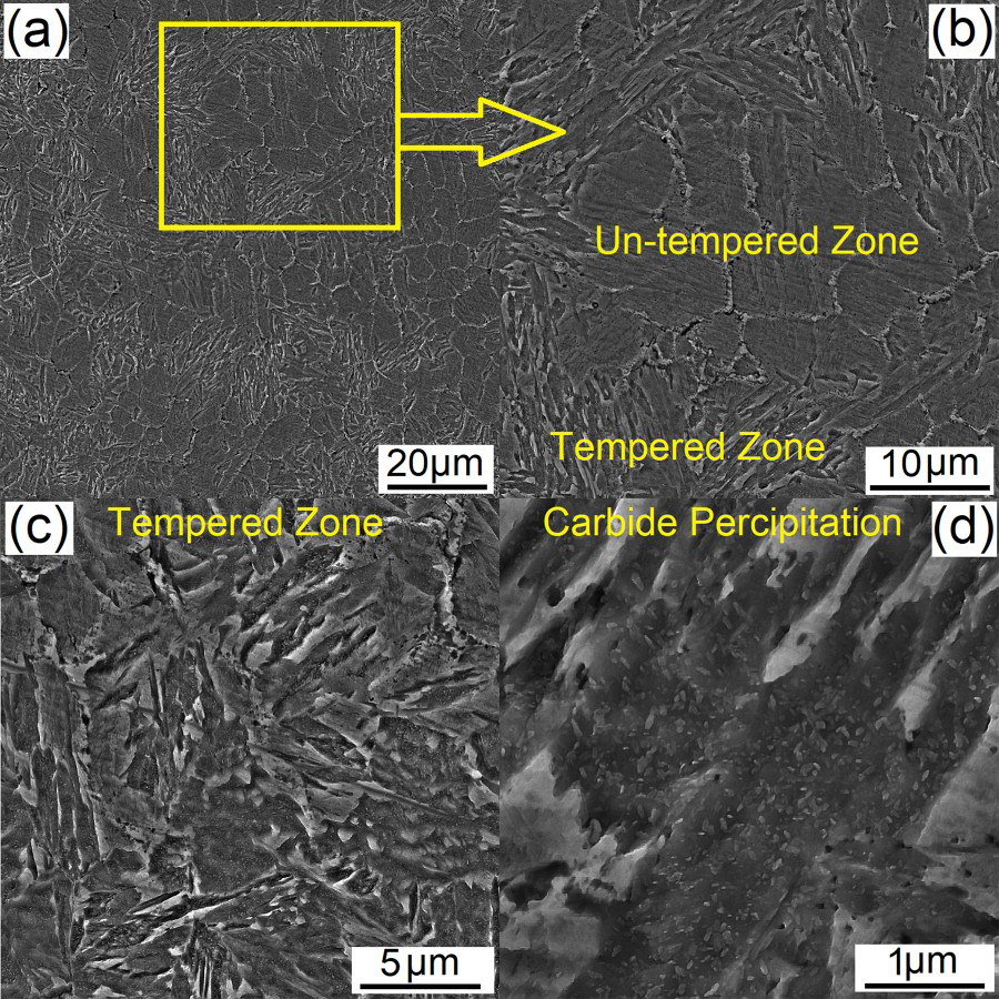
It is of note that tempering phenomena were observed at both weld nugget centre as well as the edge of the weld nugget. For instance, Figure 11 shows the FESEM micrographs of the double-pulse welds with the second pulse time of 1 s at two different locations: at the weld nugget centre and the edge of the weld nugget. According to Figure 11(a,c), at both locations, martensite lathes are broken, and the martensite decomposition is evident. Figure 11(b,d) shows higher magnification FESEM micrographs at the weld nugget centre and edge, respectively. The presence of nano-size precipitations which indicates the tempering of martensite is evident in the weld nugget. The size of the carbide particles precipitated during tempering in all double-pulse welds is less than 100 nm which is significantly smaller than the size of the primary carbides in the base metal with average length size of 700 nm. FESEM micrographs showed that increasing the second pulse time from 0.6 to 1.8 s increased the average size of the precipitated carbides in the FZ from 40 to 70 nm.
FESEM micrographs showing tempering phenomena in double-pulse weld using a second pulse time of 1s at (a,b) weld nugget centre and (c,d) weld nugget edge.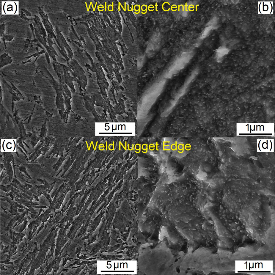
As mentioned above, the occurrence of the martensite tempering is accompanied by the hardness reduction in the weld nugget. The weld tempered with 0.6 s second pulse time exhibited reduced hardness values in the FZ by 80 HV. Increasing the temper time to 1 s does not impact the FZ hardness compared to the double pulse weld tempered using 0.6 s second pulse time. Increasing the second pulse time to 1.4 and 1.8 s resulted in the reduction of FZ hardness by approximately 100 and 120 HV, respectively, compared to single pulse weld. The hardness evolution during tempering is influenced by two factors including (i) reduction of solid solution strengthening of supersaturated carbon atoms (or reduction of dislocation density associated with Cottrell atmosphere of carbon atoms) and (ii) Ashby-Orowan strengthening of the nano-sized carbides [12]. Therefore, the hardness of tempered weld nugget is determined by the compromise of these two factors.
Enhanced peak load and energy absorption in double-pulse MSS welds
As mentioned previously, the mechanical properties of welds during the TS and CT loading conditions is governed by the FZ fracture toughness. Despite the fact that no detectable reduction in microhardness values of the FZ was observed in double-pulse weld with second pulse time of 0.2 s, the improved mechanical properties observed in this sample compared to the single pulse welds may be attributed to the redistribution/rejection of some of excess carbon in the martensite which can be accompanied with either clustering or precipitation [23]. The phenomena of clustering or precipitation were not detected using FESEM investigation carried out in the present study.
Therefore, the improved mechanical properties of the double-pulse welds with second pulse times in the range of 0.6–1.8 s can be attributed to the enhanced toughness of the tempered martensite. The improved toughness of the martensite after rapid in situ tempering can be attributed to the redistribution/rejection of the supersaturated carbon in the martensite as well as the refined carbide present in the microstructure. It is shown that high heating rate combined with very short tempering time (i.e. rapid tempering) can refine the carbide size distribution in the tempered martensite which can enhance the toughness of the martensite over the conventional slow tempering process [24-26]. The tempering cycle employed in the RSW is a rapid tempering process with high heating rate and ultra-short duration. As it is evident from micrographs given in Figures 10 and 11, the employed in situ rapid second pulse tempering enables the formation of nano-sized carbide with the average size of 40–70 nm in the FZ which can enhance the weld nugget toughness. This can explain the remarkable improvement in peak load and energy absorption of the double-pulse welds over the single pulse MSS420 resistance spot welds. It is of note that the variation of the mechanical properties in the DPWs with second pulse time in the range of 0.6–1.8 s can be attributed to variation of the FZ fracture toughness in this sample due to effect of tempering time on the extent of the tempering (i.e. dark-etching regions in OM micrographs), the content of the supersaturated carbon and size of the carbide particles. Figure 12(a,b) shows the fracture surface of the double pulse welds with second pulse current of 1 s during both TS and CT loading, respectively, indicating the presence of zones with a dimple-like feature which is the sign of the improvement in the fracture toughness of the FZ after in situ tempering.
FESEM fracture surface of the double pulse martensitic stainless steel resistance spot welds with second pulse time of 1 s after (a) the tensile-shear testing and (b) the CT testing at two magnifications.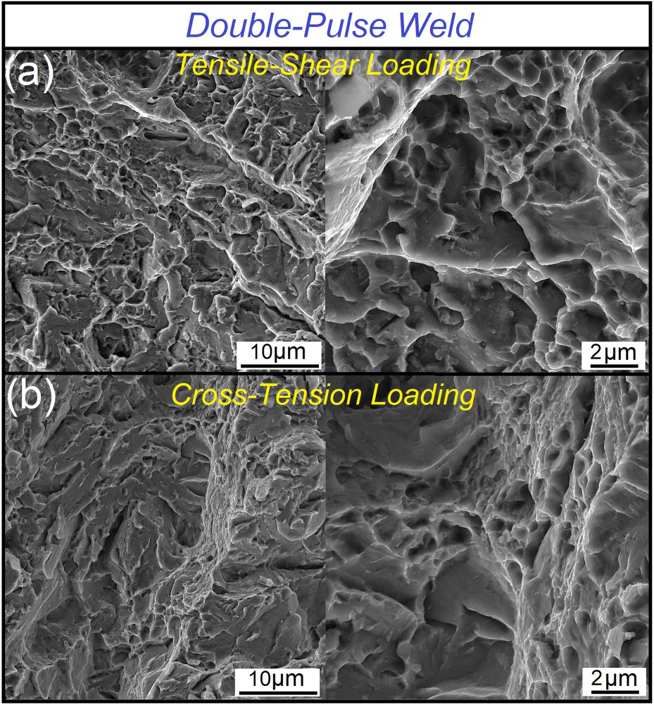
Conclusion
The resistance spot welds made on MSS using single pulse welding strategy suffers from IF with dramatically weak energy absorption which is a function of the formation of brittle FZ microstructure. It is proved that rapid post weld thermal processing via introducing a second pulse after first melting/solidification pulse can remarkably enhance the mechanical performance of the AISI420 martensitic stainless steel resistance spot welds. At proper second pulse conditions, the TS and CT peak load of double-pulse welds were enhanced over 77% and 102%, respectively. Moreover, TS and CT energy absorption of double-pulse welds improved over 240% and 1030%, respectively. The remarkable enhancement in mechanical properties is found to arise from a transition from predominantly hard martensitic microstructure in single-pulse weld to tempered martensite microstructure in double-pulse welds. The softening associated with tempering as well as precipitation of ultra-fine carbide particles are responsible for improving the toughness of the FZ.
Footnotes
Disclosure statement
No potential conflict of interest was reported by the authors.