
Abstract
The consequence of friction stir welding (FSW) and activated-gas tungsten arc welding (A-GTAW) processes on the evolution of microstructure and mechanical properties of 9Cr–1Mo (P9) steel to 316LN stainless steel dissimilar weld joint is investigated. The FSW specimen shows considerably higher tensile strength (∼652 MPa) compared to A-GTAW specimen (∼595 MPa) as well as its base metal of P9 (∼642 MPa) and 316LN (∼608 MPa) owing to the formation of tempered martensite and refined austenite in P9 and 316LN weld portion, respectively. The cross-weld tensile test revealed that the specimens failed in the base metal of 316LN SS for both FSW and A-GTAW process with ductile mode fracture. This study proves that FSW could be an alternate joining technique.
Introduction
The typical Cr–Mo ferritic steel of 9Cr–1Mo (P9)/modified 9Cr–1Mo (P91), and the class of stainless steel (SS) grade AISI type 316L/316LN is extensively used as a structural material for prototype fast-breeder reactor [1-3]. The material selections for the particular applications are based on the performance and its requirements during the in-service conditions. The steam generator components of a nuclear reactor are made of 9Cr–1Mo steel (particularly low-temperature side of boiler) which is to be connected with an intermediate heat exchanger made of 316LN SS (high-temperature side) [2, 4]. Therefore, there is a requirement of dissimilar material welding with superior mechanical properties for the design consideration of reactor components.
Currently, fusion-based welding processes typically multipass gas tungsten arc welding (GTAW) are recommended for the joining of these dissimilar materials. However, there is a metallurgical incompatibility evolved with the direct joining of ferritic steel to austenitic SS, which is summarised below [5, 6]. (i) The large difference in coefficient of thermal expansion (α) leads to high cyclic thermal stress (i.e. α for P9:12.6 μm m−1 K−1 and α for AISI 316LN SS:18.8 μm m−1 K−1), (ii) The direct mixing of these dissimilar materials end up with uncertain chemistry and two-phase morphological microstructure (martensite and austenite) and (iii) Carbon migration from ferritic steel side to austenitic weld metal (WM).
The existing research suggests that with the trimetallic joint configuration, the metallurgical issues can be solved [6]. Buttering on ferritic steel side with nickel-based alloy 800 and welding with austenitic based 16-8-2 filler on SS side to deal the α-mismatch as well as the difference in physical, mechanical and metallurgical properties. Moreover, the trimetallic configuration is expensive with complicated design and susceptible to hot cracking. Therefore, the welding parameters need to be optimised appropriately to overcome hot-cracking issues [1, 6].
The present study simplifies the intricate design configurations associated with fusion welding for joining P9 steel to 316LN SS by the solid-state welding process. Among the solid-state welding process, friction stir welding (FSW) shows an emerging technique through which successful joining can be achieved by simple joint geometry (butt-joint configuration) without significant melting and solidification. Also, feasibility is there to control the peak temperature evolution below the upper critical transformation temperature (Ac3)/even below the lower critical transformation temperature (Ac1) of the material to be welded by appropriate process parameters, thereby suppressing the formation of heat-affected zone (HAZ) and other typical melting issues [7, 8].
However, the FSW of high strength materials has raised tremendous issues during the selection of tool material because of expeditious tool wear. Therefore, materials such as polycrystalline cubic boron nitride, refractive materials (iridium, rhenium) and tungsten (W) based alloys are recommended as tool material for welding of such higher melting point/high strength alloys [9]. In this present study, tungsten lanthanum oxide (W-La2O3) tool is selected for the welding of P9 steel to 316LN SS owing to the cost effectiveness. The presence of lanthanum oxide in the tungsten base matrix improves strength and toughness via impeding dislocation motion within tungsten grains at elevated temperature [10, 11].
In this study, to explore the effectiveness of FSW weldments, activated-GTA welding (A-GTAW) was carried out, and mechanical properties were compared. Even though the plate thickness is 3 mm, A-GTAW was performed in this research study, owing to its minimum overall cost of welding (50%) [12]. In addition, an excellent weld quality, lower angular distortion, and higher productivity associated with A-GTA welding show a considerable interest in comparison to the conventional fusion welding process such as SMAW, GTAW, MIG, etc.
Materials and methods
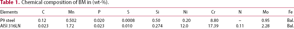
The P9/316LN plates of dimensions 300 mm (length) × 125 mm (width) × 3 mm (thickness) were used in the present study. The P9 steel base plates of normalised (1223 K, 20 min), followed by tempered (1023 K, 60 min) condition and the 316LN SS plate of solution heat-treated condition (1133 K, 30 min) were used in the present study. The chemical composition of P9 steel and 316LN SS base metal (BM) is presented in Table 1. The schematic of FSW with tool geometry is presented in Figure 1(a). The FSW processing parameters and the corresponding heat input [13] are given in Table 2. The FSW process was carried out in the position control equipment (Manufacturing Technology, Inc, USA) with different tool rotational speeds of 400, 500 and 600 rev min−1. However, during welding at 500 and 600 rev min−1, extensive tool wear was found owing to the evolution of higher peak temperature, thereby forming deleterious-banded structure in the weld. Hence, this rotational speed (500 and 600 rev min−1 was not taken for this subsequent comparative study. JMatpro software used in the present study for predicting P9 steel phase transformation temperature, and it illustrates that the austenite phase transformation starts (Ac1) at 1079 K and finished (Ac3) at 1169 K. The peak temperature evolved in the SZ matrix of FSW was approximately 1106 K, and it was calculated through the theoretical formula (1) described below [14].
Schematic view of joint configuration. Chemical composition of BM in (wt-%). The parameters employed during FSW of P9 to 316LN SS.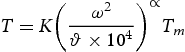
 is tool rotational speed (rev min−1),
 is the welding traverse speed (mm min−1), Tm is the melting point of P9 steel and
 are the constant K: 0.64, α: 0.04, respectively.
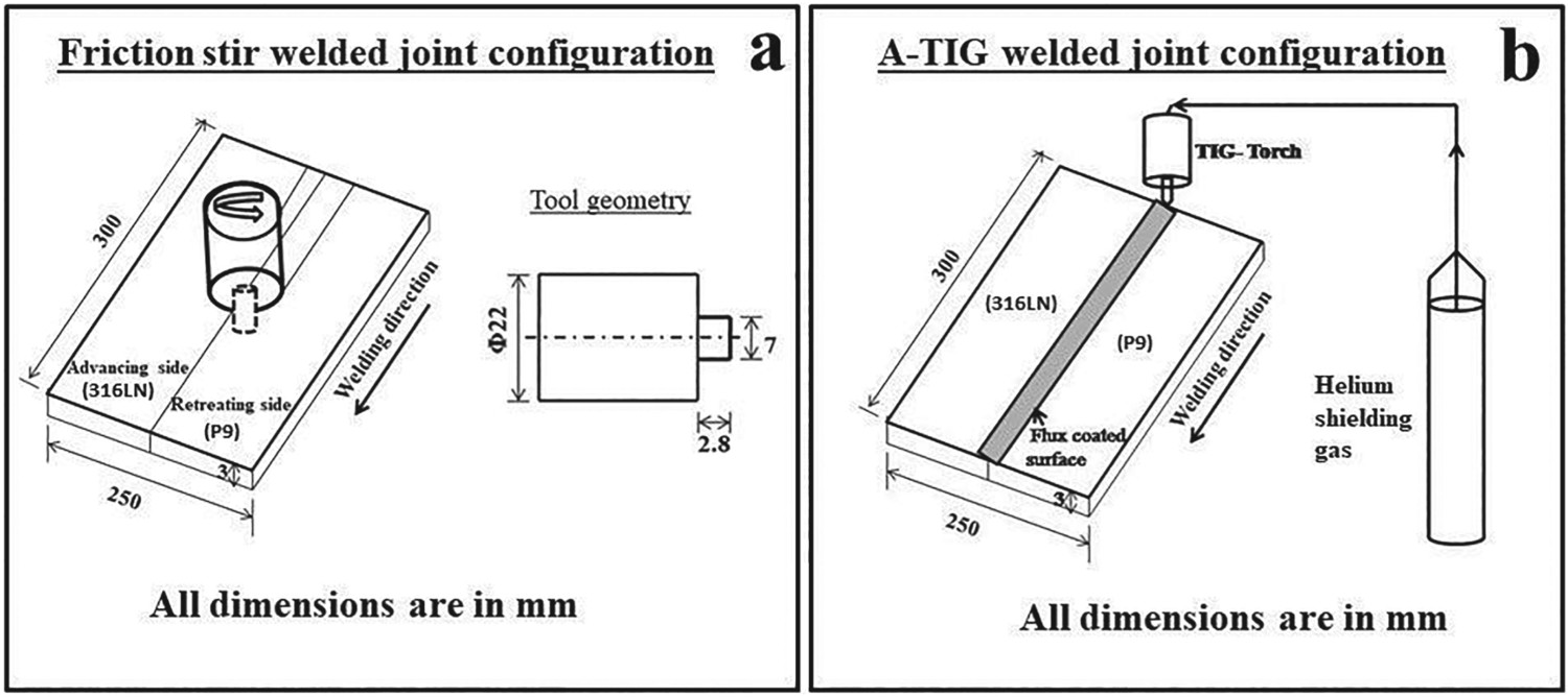

The schematic of A-GTAW is shown in Figure 1(b). Before A-GTA welding, the plates were tacked, and the joint centreline of the welds were cleaned using acetone. The selected activated flux of oxide-based multi-component powder was subjected to baking at 150°C for l h. Subsequently, the in-house fabricated activated flux mixed with acetone as a solvent and applied along the joint centreline. Once acetone evaporates, the flux dries along the joint centre line. For A-GTAW, direct current electrode negative polarity was employed through a water-cooled torch of 2% thoriated electrode (3 mm diameter). The shielding gas used was pure helium with a flow rate of 15 L min−1. The A-GTA welding process parameters and its equivalent heat input [15] are presented in Table 3. The X-ray radiography-qualified weld joints were subjected to post-weld heat treatment (PWHT) as per the schematic shown in Figure 2.
Schematic diagram of post-weld heat treatment cycle. The A-GTAW welding parameters for welding of P9 to 316LN SS.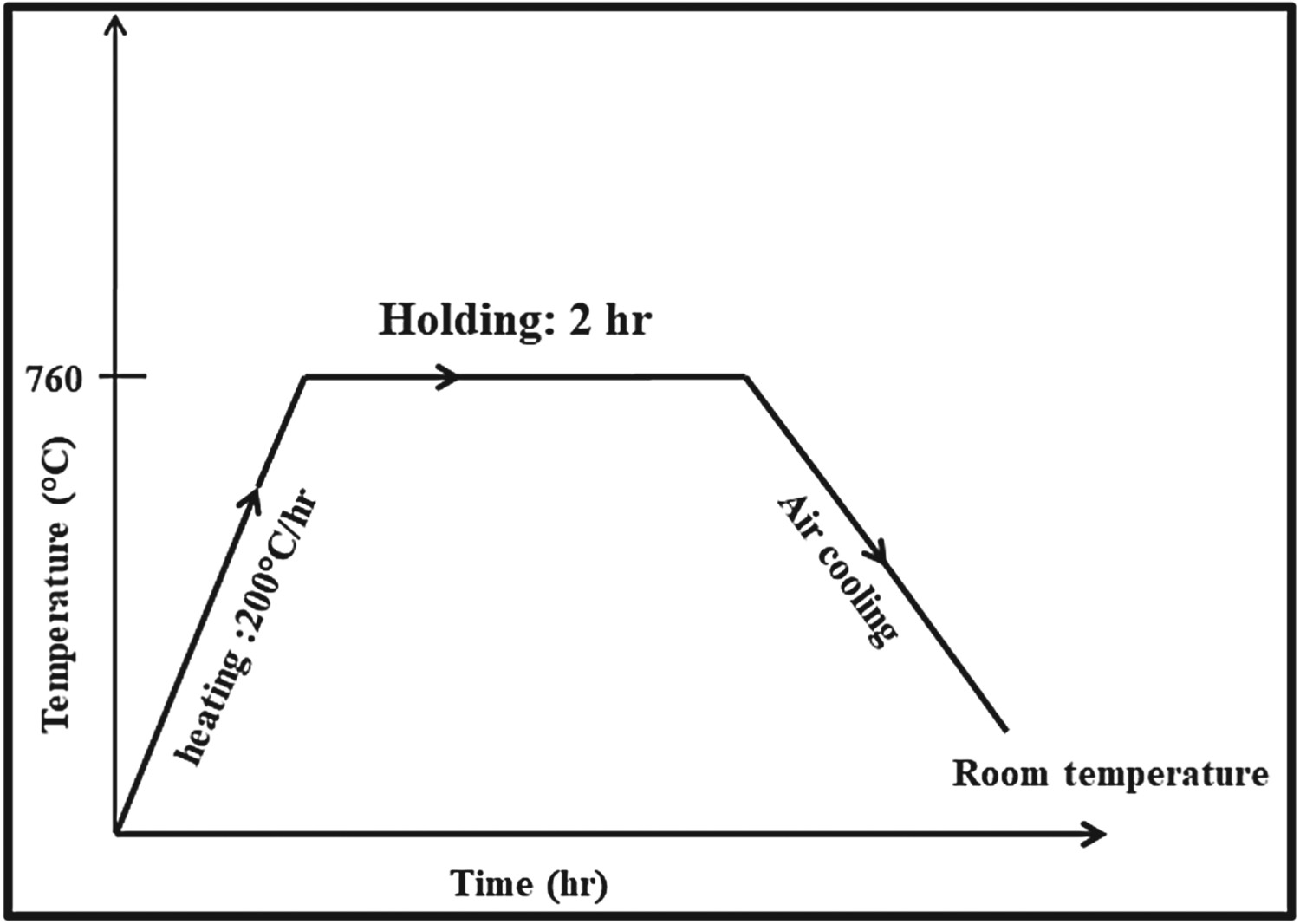

The weld specimens were metallographically polished to 1 µm finish for microstructure characterisation and hardness measurement. The P9 side of polished specimens was etched with Villella's reagent, and 316LN SS side of weld specimen is electrolytically etched with 10% oxalic acid to reveal the microstructure. The microstructure of the weldment was studied via an optical microscope and scanning electron microscope (SEM). The electrolytic polishing (15% perchloric acid + 85% methyl alcohol solution) was done to obtain electron backscatter diffraction (EBSD) mapping by FEI quanta 200 HV SEM system. The hardness measurements were carried out by Vickers microhardness tester using 200 g load with the dwell period of 15 s. The tensile specimens were fabricated as per the ASTM E8-M standard. The ambient temperature tensile test was carried out with 100KN capacity servo-hydraulic machine (Hung Ta-2402) at a crosshead speed of 0.3 mm min−1 corresponding to the strain rate of
 . The fractured surfaces of the specimen were analysed using SEM to characterise the failure mode.
Results and discussion
Base metal microstructure characterisation
The BM microstructure of the P9 steel and 316LN SS specimens used in the present study are explained with EBSD map in Figure 3. The normalised and tempered condition of P9 BM reveals that the tempered martensitic microstructure within the prior austenite grain boundary (PAGBs). A fine decorated white precipitate was observed in the PAGB as well as in lath boundary. This is further analysed with the help of Energy Dispersive Spectroscopy (EDS), which confirmed the presence of M and C; it corresponds to the stoichiometry of M23C6. The carbide precipitates in PAGBs help to impede the dislocation motion, whereas the precipitates in the lath boundary prevent the lath coarsening, thereby increasing creep strength (P9) at the higher temperature. The solution annealed BM of 316LN SS shows equiaxed austenitic structure with annealing twins. The average grain size of the P9 and 316LN BM is ∼12 ± 2 μm and ∼23 ± 5 μm, respectively.
EBSD analysis (a) & (b) P9 BM (c) & (d) 316LN BM.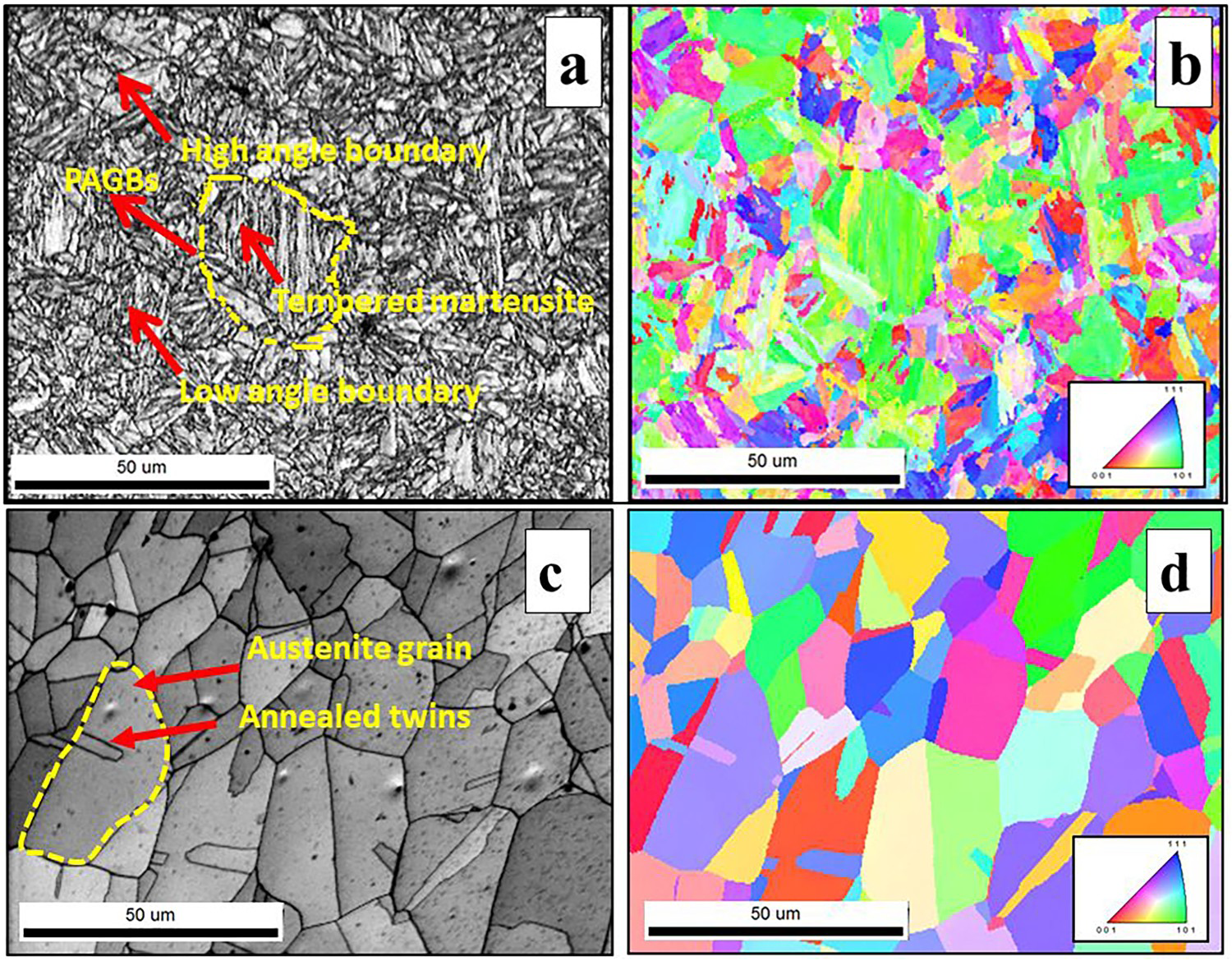
Microstructure evolution in the as-welded condition
Optical macrograph of the FSW weldments and its corresponding evolutionary zones are shown in Figure 4. It is highlighting that the tool geometry design and heat input evolved with FSW parameters are adequate enough to weld the 3 mm thick dissimilar weld with complete penetration and defect-free. The cross-section of joints was characterised as stir zone (SZ), thermomechanical-affected zone (TMAZ) and HAZ, showing better intermixing without tool wear/degradation.
Cross-sectional microscopic view of FSW weldments.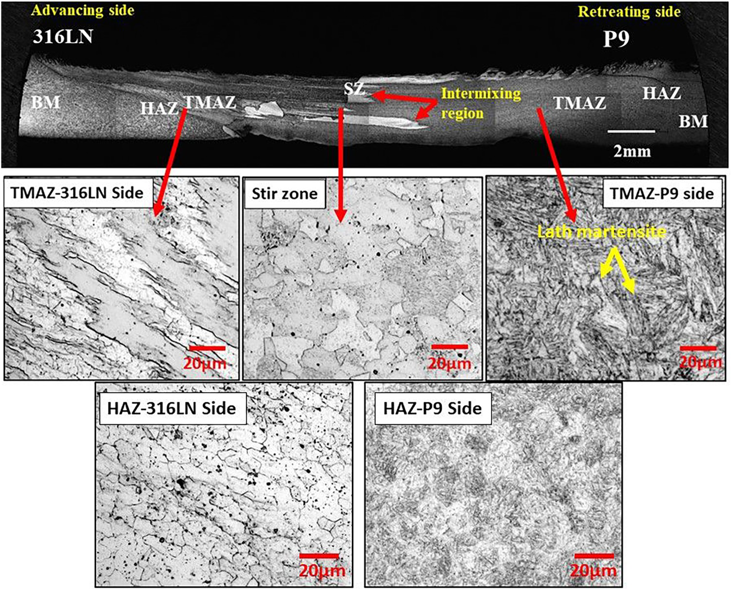
The SZ matrix (interface) of the dissimilar weld shows mixed finely refined austenite and martensitic structure owing to the effect of dynamic recrystallisation associated with hot deformation during FSW. The peak temperature evolved during FSW of P9 steel was close to Ac3 temperature (1106 < 1169 K) and thereby martensite transformation was found in the SZ and TMAZ (Figure 4) [10]. Similar peak temperature values were reported for RAFM steel during FSW [16]. The HAZ peak temperature might have crossed just above Ac1 temperature (P9). Therefore, during the heating cycle of FSW, a part of ferrite in the BM transformed to austenite and subsequent cooling it transformed to finer martensite, thereby suppressing the grain coarsening phenomenon in the HAZ. In addition, the result of line scan analysis at the joint interface (Figure 5) interprets a good metallurgical bonding through atomic diffusion via primary elements such as Fe, Cr, Ni from 316LN to P9 side. Deformed austenite grains were observed in the TMAZ of 316LN side along the direction of tool rotation. A very narrow HAZ was found in the 316LN side, which contains finer austenitic grains. However, the HAZ width of P9 side (∼2 mm) is comparatively larger than HAZ of 316LN (∼0.5 mm) owing to higher thermal conductivity.
Line scan analysis of the joint interface of the FSW dissimilar weldments.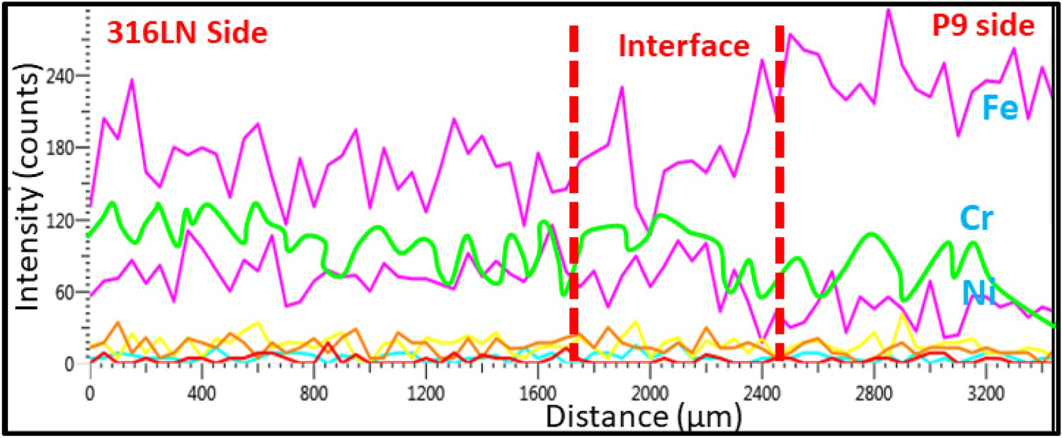
The EBSD analysis clearly emphasises that the grains were randomly orientated with dual-phase (Figure 6(a,b)) microstructure such as austenite and martensite. At the joint interface of the SZ matrix, there is a continuous distribution of recrystallised grains and lath-martensitic structure. The colour contour map of Figure 6(c) represents the density fraction of austenite (1.7%, green) and ferrite (98.3%, red) phases in the SZ matrix. The density distribution of low angle grain boundary (LAGB) and high angle grain boundary (HAGB) of 316LN BM was ∼9.7% and ∼90.3%, respectively, whereas the SZ matrix contains 47.3% of LAGB and 52.7% of HAGB. The severe plastic deformation associated with FSW induces the dislocation, and owing to the recovery effect, it gets rearranged in the form of low energy cells or subgrains [17]. Therefore, the density fraction of LAGBs in the SZ is comparatively higher than that of 316LN BM.
EBSD analysis (a) image quality figure (FSW-SZ), (b) grain boundary orientation map (FSW–SZ), (c) phase mapping result (FSW–SZ), (d) image quality figure (A-GTAW-weld), (e) Grain boundary orientation map (A-GTAW-weld) and (f) phase mapping result (A-GTAW-weld).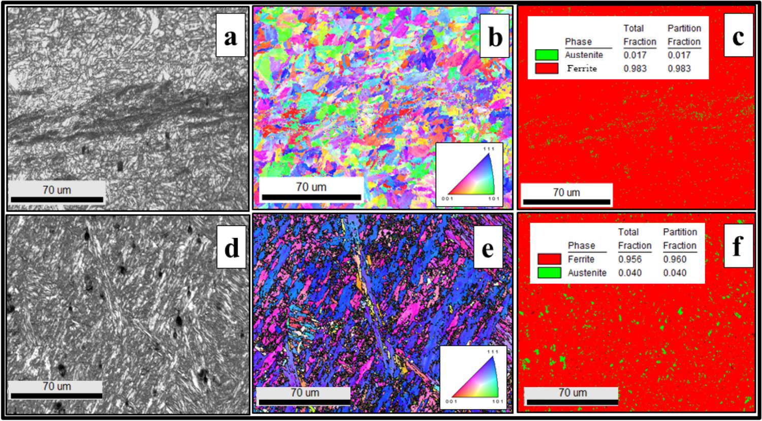
The cross-sectional view of A-GTAW weldment reveals full penetration and defect-free joint and its corresponding zone wise microstructure are showed in Figure 7. Also, the macrograph emphasises that the weldment is asymmetric owing to the difference in thermal properties between P9 and 316LN. The macrograph of A-GTAW weldments shows distinct regions of WM, coarse grain heat-affected zone (CGHAZ), fine grain heat-affected zone (FGHAZ), inter critical heat-affected zone (ICHAZ) and BM (Figure 7(a)). The WM microstructure near P9 steel shows the typical lath-martensitic structure as expected and two-phase microstructure (retained austenite and lath martensite) from the weld centre towards 316LN side (Figure 6(d–f)). The microstructure observed in the centre of the dissimilar weld is in good agreement with microstructure predicted by Schaeffler diagram (Creq: 14.9% and Nieq: 9.5%) as shown in Figure 7(b). The CGHAZ of P9 steel side (weld thermal cycle experienced above Ac3 and below Ac4) comprises of lath-martensitic structure within the PAGBs of grain size ∼35 ± 2 μm. During this temperature range, M23C6 precipitates dissolve and grain boundaries are free from pining force/obstacle, which in turn results in grain coarsening [14]. Similarly, a fine grain martensitic structure of grain size ∼13 ± 2 μm was found in the FGHAZ (weld thermal cycle just above Ac3). In the ICHAZ (weld thermal cycle just above Ac1), a mixture of tempered martensitic structure, austenitic transformation products and untransformed ferrite was observed. The overall width of the HAZ in P9 side and 316LN side was approximately 3.8 and 250 μm, respectively. In addition, vermicular δ-ferrite was also found in the HAZ of 316LN stainless steel. The EDS analysis in the δ-ferrite region shows the higher chromium content along with other solid solution elements. As different sorts of weld thermal cycle were experienced between A-GTAW and FSW process, the overall width of HAZ in A-GTAW weldments were comparatively higher than FSW weldments. However, in both the welding processes, undesirable martensite was present in the WM and HAZ of P9 steel side owing to which the weld joints were subjected to PWHT at 760°C for 2 h.
Microstructure analysis of the A-GTAW weldments (a) zone wise microstructure and (b) Schaeffler diagram shows the microstructure in the centre of dissimilar weld (red spot).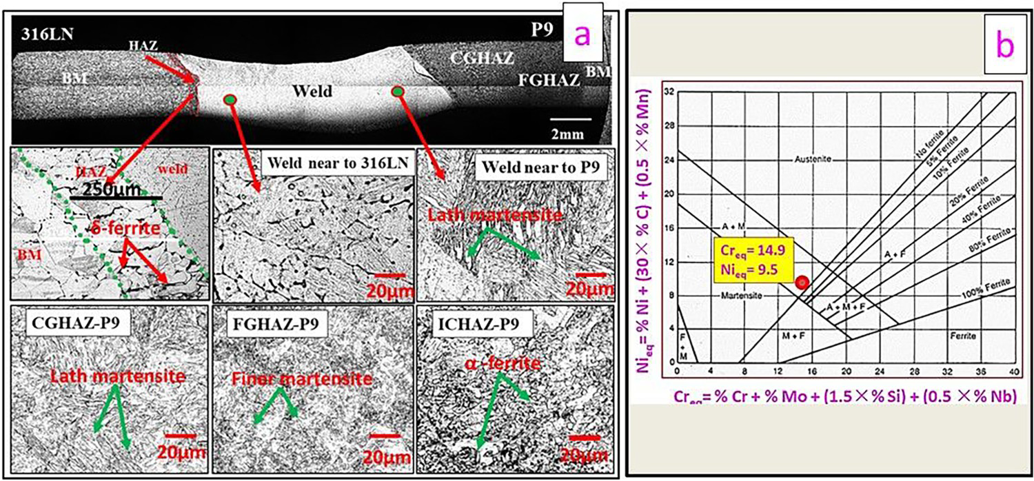
Microstructure evolution during PWHT
It is interesting to observe that the weld macrograph (Figure 8(a)) consists of black and white layers in the joint interface after PWHT. The further analysis of the joint interface indicates that the black region is carbon enriched, and the white region is carbon depleted layers [18]. The diffusion is a thermally activated process; carbon migration from the P9 side to 316LN was observed during PWHT. The accelerating force for this phenomenon is the carbon activity gradient across the weldments. Since the carbon solubility in the P9 steel is limited, the excess carbon diffuses into the soluble region of 316LN. Therefore, the joint interface of the P9 side shows a white layer of carbon denuded region, which tends to nucleate as a soft α-ferrite and gets coarsened during PWHT (Figure 8(a)). However, the un-tempered martensite transforms into tempered martensite in the TMAZ and HAZ of P9 side, whereas recrystallised refined austenitic grains in the 316LN side gets coarsened during PWHT. In contrast, the microstructure (Figure 8(b)) evolved during PWHT of A-GTAW WM shows visible austenite grain boundary. The martensite present in the HAZ and near to the fusion zone of P9 side gets tempered, whereas the austenite grains in the HAZ of 316LN gets coarsened. The EDS analysis of the WM reveals that the concentration of chromium, nickel and molybdenum is high in the PWHT compared to the as-welded condition, which is attributed to the thermal diffusion-assisted mechanism.
Microstructure evolution of PWHT specimen (a) FSW and (b) A-GTAW.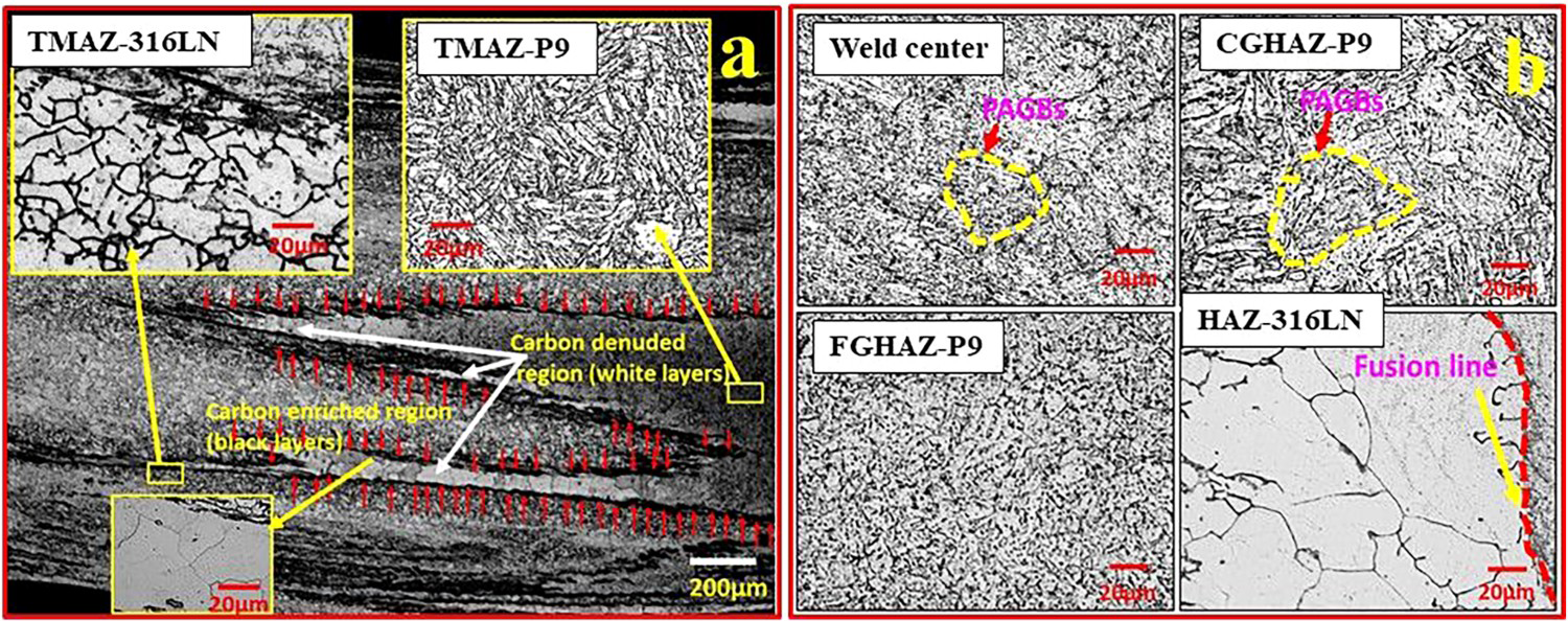
Mechanical properties characterisation
The hardness profile across the transverse direction was carried out approximately at mid-thickness of the weld. The initial observation (Figure 9(a)) reveals that there is an uphill and downhill mode of hardness fluctuation across the FSW weld owing to the evolution of heterogeneous microstructure via mechanical mixing. In the as-welded FSW specimen, the maximum hardness observed was ∼430HV0.2 and ∼230HV0.2 for P9 and 316LN side, which is attributed to the martensitic structure with higher dislocation density and the presence of refined austenitic grain, respectively (Figure 9(a)). In contrast, in the case of A-GTAW-weld, it shows an average hardness of ∼420HV0.2 (Figure 9(b)) owing to the existence of two-phase microstructure (martensite and austenite). Since the weld underwent melting and re-solidification, no significant variation in hardness profile was observed when compared with FSW weld. The HAZ hardness (for both FSW and A-GTAW specimen) gradually decreases towards the BM owing to the microstructure variation.
Vickers microhardness profile (a) across the FSW specimen, (b) across the A-GTAW specimen, (c) from stir face to root of FSW specimen and (d) weld metal of A-GTAW specimen.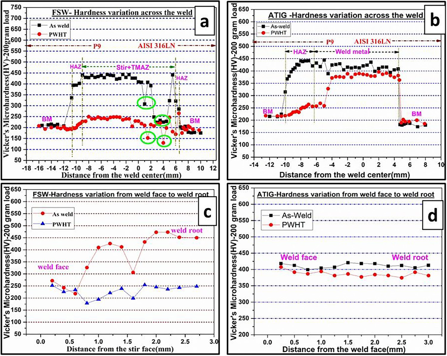
After PWHT, the FSW weldment hardness gradually decreases, especially in the P9 side owing to the presence of tempered martensite (Figure 9(a)). However, it is interestingly observed that FSW weld shows a steep hardness drop of ∼150HV0.2 in the intermixing zone of P9/316LN (i.e. carbon denuded α-ferrite region, Figure 8(a)). Hardness measurement confirms that the diffusion kinetics of carbon migration across the joint interface of FSW weld during PWHT. However, such kind of hardness drop/soft zone formations was not found in the A-GTAW specimen after PWHT (Figure 9(b)). However, after PWHT of A-GTAW-weld, hardness decreases significantly near to the fusion zone and complete HAZ of P9 side owing to the presence of tempered martensite. Moreover, along the 316LN side of the A-GTAW weldments hardness decrement was not observed which is owing to the complex weld chemistry as well as diffusion of nickel (Ni) from the 316LN BM to WM resulting in the decrease of austenitic transformation temperature of the weld. Therefore, PWHT temperature employed in the present study might be above the Ac1 temperature and hence, on subsequent cooling, martensite morphology with higher hardness was observed after PWHT.
Also, the hardness profile shows that the hardness of the tempered martensite in the weld/HAZ of the P9 side is just above the hardness of P9 BM (Figure 9 (a,b)) indicating insufficient PWHT duration. Furthermore, hardness along the longitudinal direction of the weld centre was carried out to find the weld homogeneity. It is noticed that (Figure 9(c)) hardness of the FSW weld is increased wherever the martensitic structure was present and dropped in the hardness wherever the austenitic structure is present, and subsequent hardness reduction was found after PWHT. However, in the case of A-GTAW-weld, uniform hardness profile was observed (Figure 9(d)) and insignificant hardness reduction even after PWHT.
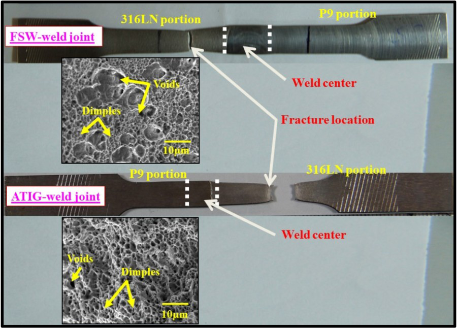
The results obtained from the tensile test (Figure 10) shows that the ultimate tensile strength (UTS) achieved for the friction stir weld specimen (∼652 MPa) is comparatively higher than that of A-GTA weld specimen (∼595 MPa) as well as its BM of P9 (∼642 MPa) and 316LN (∼608 MPa). In addition, the FSW weldments exhibit the higher yield strength and percentage of elongation than that of A-GTA weldments owing to the existence of the tempered martensitic microstructure in the P9 side and refined austenite grains in the 316LN side of the weldments. The PWHT specimens of A-GTA weld exhibit an un-tempered martensitic microstructure with complex weld chemistry which is the reason for obtaining lower elongation in comparison to FSW weld specimen. However, the cross-weld tensile specimens of both FSW and A-GTAW weldments were fractured in the 316LN BM (Figure 11). The SEM fractography shows dimple pattern morphology with tear ridges and voids, indicating the ductile mode of fracture (Figure 11). Even though the soft zone formation was present in the SZ matrix of FSW specimen, the occurrence of tempered martensite and refined austenite in the adjacent regions provided the restraint effect and thereby weld remained stronger. Therefore, higher strength achieved in the FSW process signifies that the FSW process becomes a potential alternating technique for welding of P9 steel to 316LN SS.
Tensile properties of FSW and A-GTAW-weld joint. Photograph of tensile fractured specimen and its fractograph.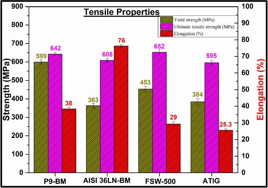
Conclusion
The significant findings and observations from this comparative study of friction stir and A-GTA dissimilar welding between P9 steel to AISI 316LN SS are summarised below.
This study proves the application/feasibility of W-La2O3 tool for FSW of high-temperature materials without any tool wear. FSW process produced an excellent mechanical bonding between P9 steel to 316LN stainless steel. The microstructure of the P9 side shows lath-martensite, and 316LN side shows refined austenite. However, A-GTAW-weld shows a dual-phase (austenite and martensite) morphology throughout the weld with large volume of intermixing. The A-GTAW-weld revealed δ-ferrite in HAZ of 316LN side which is a detrimental phase for high-temperature application, whereas in the FSW weldment, the nucleation and growth of δ-ferrite were absent. The HAZ thickness was drastically decreased with the FSW process (P9 side HAZ width is ∼2 mm for FSW and ∼3.8 mm for A-GTAW-weld). This study highlights that there is a scope to avoid martensite formation by limiting the peak temperature below the Ac1 temperature by reducing tool rpm, thus avoiding PWHT and thereby suppressing soft zone formation. Even with soft zone formation, superior tensile properties were achieved in the FSW weldments than A-GTAW. Exceptionally higher UTS (∼652 MPa) achieved owing to the restraint effect from tempered martensitic microstructure and refined austenite grains. Therefore, this study proves that the FSW could be a potential and alternative technique for welding of P9 steel to 316LN stainless steel.
Footnotes
Disclosure statement
No potential conflict of interest was reported by the authors.