
Abstract
The formation and control of the residual δ-ferrite in Alloy 617/9% Cr dissimilar welded joint manufactured by the single-layer or multi-layer multi-pass overlaying technique were comparatively investigated. The residual δ-ferrite was identified based on its lower microhardness and carbon content than the surrounding martensite matrix and being free from precipitates. Patch-shape residual δ-ferrite was found in the heat-affected zone (HAZ) of 9% Cr steel adjacent to the fusion line for the single-layer overlaying weldment, while less and smaller residual δ-ferrite could be achieved by employing the multi-layer multi-pass overlaying technique. Attributing to the optimisation of the subsequent thermal input and heat transfer, the technique utilised in this study was proved to be effective to control the formation of residual δ-ferrite.
Keywords
Introduction
With the increasing demand for energy saving and emission reduction, the ultra-super-critical (USC) technique based on the enhancement of steam working pressure and working temperature has been extensively investigated and applied in the power generation industry [1]. The elevated steam working parameters call for more severe requirements on the strength, corrosion resistance, and creep properties of materials, and this in return promotes the mechanical property improvement for high-temperature steels [2]. To fulfil these requirements, the 9–12% Cr steels [3] and Alloy 617 Ni-based alloy [4] were developed and regarded as one of the ideal candidates for the USC circumstance. To make full use of different materials and reduce costs simultaneously, the welding technique of dissimilar materials was therefore developed and broadly utilised in various industrial fields, especially the manufacture of the structural components with heavy section [5, 6]. Among these welding techniques, the gas tungsten arc welding (GTAW) has become one of the most extensively employed methods for its advantages, such as high-quality weld metal (WM) deposits, great precision, and superior surfaces [7].
As for welded joints, phase transition was crucial for its microstructure stability and mechanical properties, like tensile strength [8], corrosion resistance [9], and impact toughness [10]. Although high Cr steels normally consisted of martensite, the residual δ-ferrite was susceptible to form under non-equilibrium conditions. During the welding process, the rapid cooling could lead to the incomplete phase transition from δ-ferrite to austenite [11]. Besides, the ferrite stabilising elements (e.g. Cr, Mo, V, and W) were favourable to promote the formation of δ-ferrite at high temperatures [12]. Some studies revealed that the residual δ-ferrite could damage welded joints by deteriorating the impact toughness [13] and creep properties [14-16]. Moon et al. [17] pointed out that the Cr-depleted zones tended to form along the residual δ-ferrite in Fe–18Cr–10Mn–N steel welded joint and decreased the corrosion resistance. Wang et al. [18] illustrated that the residual δ-ferrite could provide the prior sites for cavity initiation and therefore impair the creep resistance of modified 9% Cr steel welded joints. Pandey et al. [19] found that the degradation in the ultimate tensile strength of P91/P92 dissimilar welded joints was due to the formation of soft residual δ-ferrite patches. Thus, the formation and existence of residual δ-ferrite were generally harmful to the mechanical properties of welded joints, and in this case, its formation mechanism and control should be emphasised.
In the present study, the formation and distribution of the residual δ-ferrite in the single-layer or multi-layer multi-pass welding specimens were comparatively investigated based on the microstructure characterisation and microhardness measurement. In addition, the technique and strategy to control the residual δ-ferrite in 9% Cr-HAZ of Alloy 617/9% Cr dissimilar welded joint were further probed.
Experimental procedures
The 9% Cr steel and Alloy 617 nickel-based alloy were chosen as the base metals (BMs) for the dissimilar welded joint. The 617 welding wires were selected as the filler for both overlays and butt welds (Table 1). The GTAW processes accompanied with the single-layer or multi-layer multi-pass techniques were conducted on the 9% Cr steel and Alloy 617 plates with a thickness of 50 mm to fabricate the welded joints. The joint design of the dissimilar weldment was schematically shown in Figure 1. During the welding process, the welding voltage and current for each pass were about 11.5 V and 180 A, respectively. The welded joints were fabricated with the interpass temperature of 150 °C and the welding speed of about 80 cm min−1. After welding, the single-layer or multi-layer multi-pass specimens with appropriate size were taken from the weldment for microstructure characterisation. The polished specimens were etched by a mixture solvent of HCl + HNO3 + H2O with the volume proportion of 3:3:7. Optical microscope (OM, Zeiss Image A2m) and scanning electron microscope (SEM, JSM-6700F) were utilised for the microstructure observation. The element distribution of 9% Cr-HAZ around the fusion line was revealed by the electron probe micro-analyzer (EPMA, Shimadzu 8050G). In addition, the microhardness in some specially chosen zones was tested by a Vickers hardness tester (MH-5L) with a constant load of 50 gf and holding for 10 s.
Schematic of the joint design for Alloy 617/9% Cr dissimilar welded joint (all dimensions in mm). Chemical composition of 9% Cr steel, Alloy 617, and filler (wt-%).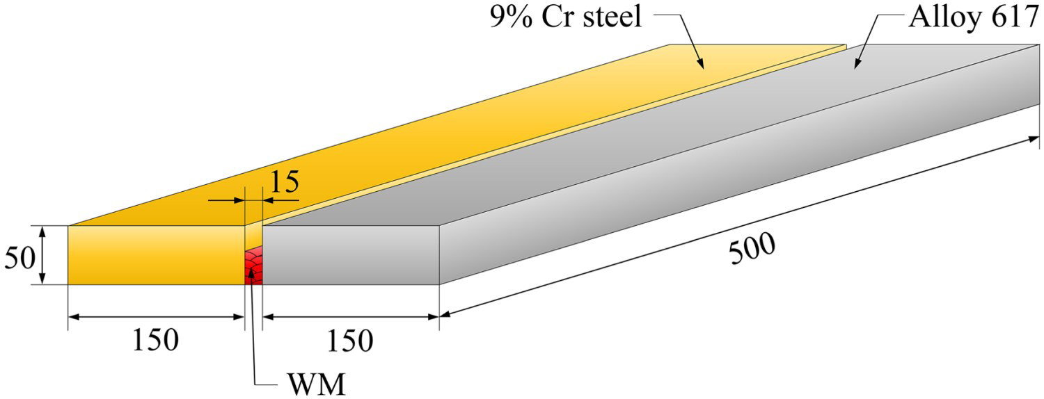
Results and discussion
Microstructure of the GTAW overlaying welded joint
Figure 2 presented the metallographic microstructure of the dissimilar welded joint manufactured by the single-layer GTAW overlaying method. Figure 2(a) showed that the patch microstructure distributed continuously in 9% Cr-HAZ along the fusion line, exhibiting various sizes and morphologies [Figure 2(b,c)]. The thermal effect could be reflected by the length of WM on 9% Cr-BM in the cross section of the welded joint, which was defined as the contact length. The contact length in the single-layer joint was about 9.2 mm and the 9% Cr-HAZ experienced the thermal effect once. Pandey et al. [20] also found the analogous patches with lower microhardness in 9% Cr steel welded joint as compared with the surrounding martensite, proving them to be the residual δ-ferrite. Grobner et al. [21] deemed that the residual δ-ferrite in the 9% Cr steel was well identifiable because nearly no precipitates existed inside. In order to characterise the patch microstructure in 9% Cr-HAZ close to the fusion line, microhardness test, microstructure observation, and element distribution were further carried out.
Microstructure of the single-layer welded joint manufactured by GTAW overlaying method: (a) macrostructure of the single-layer specimen; (b,c) enlarged images corresponding to the rectangles A and B in (a), respectively.
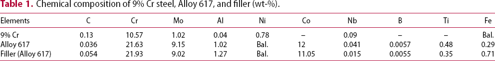
Figure 3 showed the microhardness of the patches and surrounding martensite matrix in 9% Cr-HAZ of Alloy 617/9% Cr dissimilar welded joint. As shown in Figure 3(a–e), the microhardness of the patch zones ranged from 175 to 188 HV. On the contrary, the surrounding martensite matrix revealed the microhardness from 473 to 487 HV [Figure 3(f–j)]. A great microhardness discrepancy between the patches and surrounding microstructure was confirmed. The location with a remarkable hardness gradient generally acted as the weak link of the welded joint [22]. The stress concentration tended to be produced at the interface with a sudden change of microhardness under the influence of the external thermal and/or stress during the actual service [23]. On this occasion, the premature fracture failure of the workpiece might happen.
Microhardness of the δ-ferrite and surrounding martensite matrix in 9% Cr-HAZ.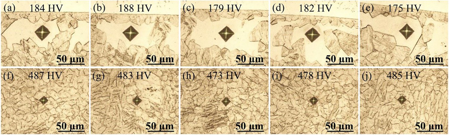
The microstructure and element mapping results of 9% Cr-HAZ around the fusion line were exhibited in Figure 4. Figure 4(a) showed that 9% Cr-HAZ was composed of the martensite matrix and an amount of second phases in patch shape and various sizes. It was interesting to notice that these patches were free from precipitates. Figure 4(b) revealed the lower content of element C in these patches as compared to the surrounding martensite matrix. Owing to the outward diffusion of the element C during its formation process, the residual δ-ferrite was usually free from carbides [24]. Based on the microhardness, microstructure, and element distribution of the special zone, here these patches in 9% Cr-HAZ were determined as residual δ-ferrite.
Microstructure of Alloy 617/9% Cr dissimilar welded joint fabricated by GTAW overlaying process: (a) SEM image around the fusion line in 9% Cr side; (b) EPMA element mapping highlighting the carbon distribution of the framed zone in (a).
Formation and distribution of the residual δ-ferrite in dissimilar welded joint
Figure 5 illustrated the calculated equilibrium phase diagram of the 9% Cr steel and schematic for the formation of the residual δ-ferrite under non-equilibrium conditions. Clearly, the δ-ferrite tended to form at a temperature range between 1500°C and 1150°C. During the welding process, the temperature of 9% Cr-HAZ close to the fusion line suffered the peak temperature above 1500°C, which could facilitate the formation of δ-ferrite. Meanwhile, the ferrite stabilising elements, such as Cr and Mo in 9% Cr steel, could further promote the δ-ferrite formation. During the cooling process, the phase transition from the primary δ-ferrite to austenite started at about 1300°C and finished at 1150°C in the equilibrium state. However, the change of solidification microstructure and formation of metastable phases were generally expected under non-equilibrium conditions [25]. Some δ-ferrite could not totally transform into austenite due to the rapid cooling rate during welding and retained partially in 9% Cr-HAZ.
Equilibrium phase diagram of the investigated 9% Cr steel based on the results calculated by Pandat software and schematic for the δ-ferrite formation under non-equilibrium conditions (colorful part).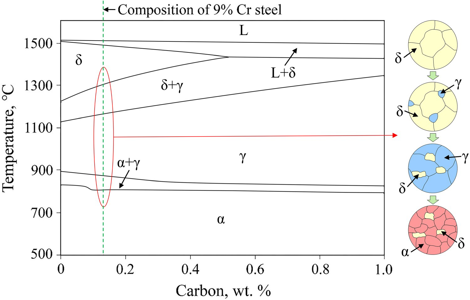
To shed much light on this process, a schematic for the formation and distribution of the residual δ-ferrite in 9% Cr-HAZ was shown in Figure 6. Figure 6(a,b) exhibited that the residual δ-ferrite appeared along the fusion line in 9% Cr side due to the welding thermal effect. Furthermore, it was worth mentioning that the residual δ-ferrite in 9% Cr-HAZ existed at a certain distance from the fusion line. The residual δ-ferrite in the vicinity of the fusion line was presumably caused by the diffusion of the austenite forming elements, especially Ni, from the WM to 9% Cr-HAZ during welding. Figure 6(c) displayed the element diffusion during the formation of the residual δ-ferrite. Chen et al. [26] found the decreasing content of the element Ni from the Ni-based alloy WM to the low-alloy steel in dissimilar welded joints. A similar phenomenon was also reported by Mittal et al. [27], where the diffusion of element Ni from the high Ni content WM to HAZ was detected in T91/347H dissimilar welded joint. With the diffusion of the austenite forming element across the interface from WM to 9% Cr steel, the formation of the δ-ferrite in 9% Cr-HAZ close to the fusion line was suppressed. Meanwhile, the diffusion distance of alloying elements was limited by the insufficient time at high temperature during welding. Ultimately, the residual δ-ferrite formed near the fusion line in 9% Cr-HAZ.
Schematic of the formation and distribution for the residual δ-ferrite in 9% Cr-HAZ of the single-layer welded joint manufactured by GTAW overlaying: (a) top view; (b) left view; (c) the residual δ-ferrite distributing at a distance from the fusion line in 9% Cr-HAZ with the element diffusion across the interface between WM and 9% Cr steel. CGZ: coarse grain zone, FGZ: fine grain zone.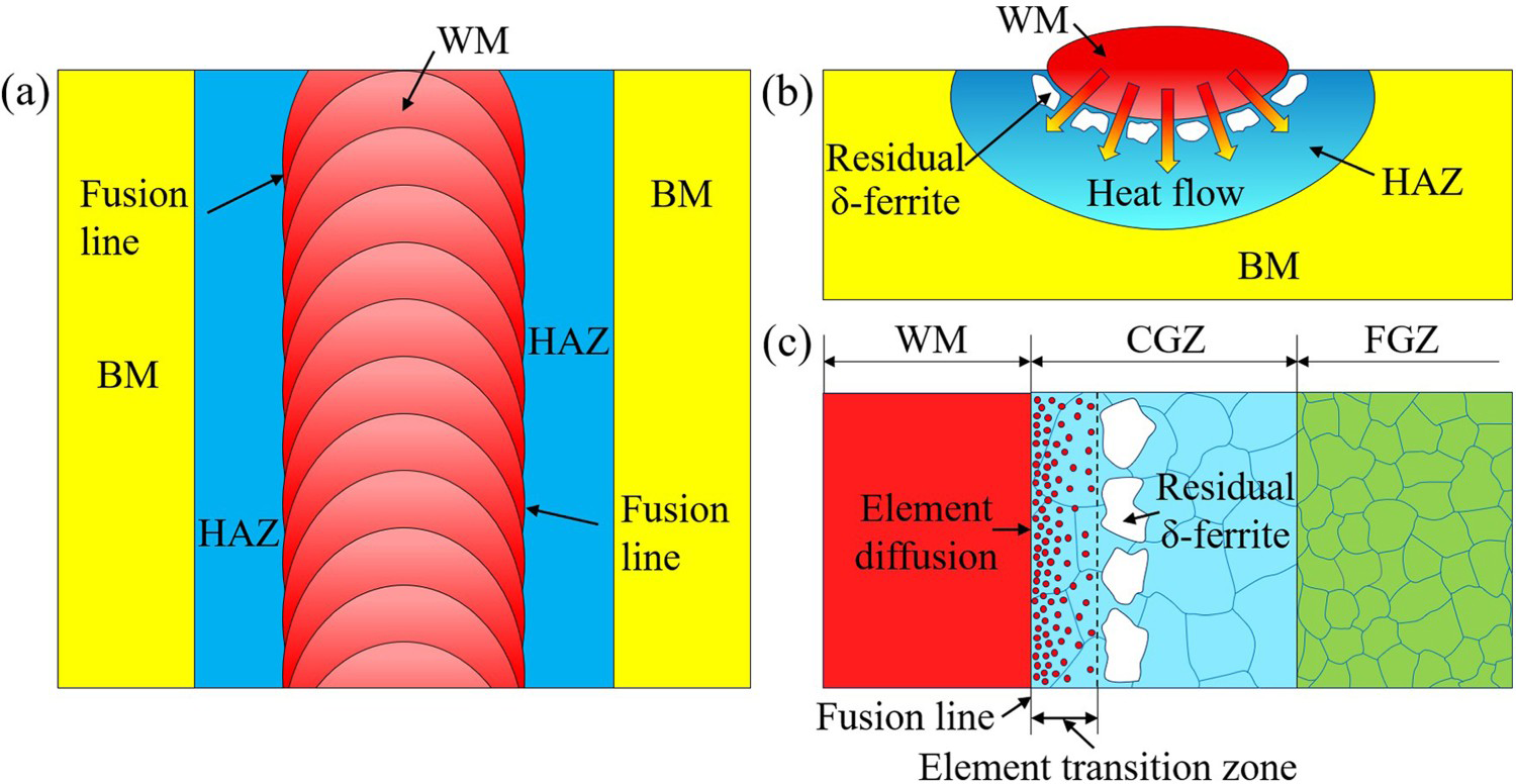
Residual δ-ferrite in the multi-layer multi-pass overlaying welded joint
The distribution of the residual δ-ferrite in the GTAW overlaying weldment fabricated by the multi-layer multi-pass technique was displayed in Figure 7. Unlike the residual δ-ferrite observed in the single-layer welded joint (Figure 2), fewer residual δ-ferrites with smaller size distributed discontinuously along the fusion line (Figure 7). The reduction in the amount and size of the residual δ-ferrite was observed within the intersecting HAZ of the two adjacent welding passes, as shown in Figure 7(d). Owing to the multi-layer and multi-pass technique, the welded zone formed by the previous welding layers and welding passes could be reheated by the latter ones, resulting in different zones with heterogeneous microstructure. Compared with the single-layer one, the subsequent thermal effect on the former welded zone during multiple steps welding was regarded as the primary cause for the uneven distribution of the residual δ-ferrite in 9% Cr-HAZ.
Microstructure of the multi-layer multi-pass overlaying joint: (a) OM image of the zone consisting of 9% Cr-HAZ and WM; (b–e) microstructure details of the regions A to D marked in (a), respectively.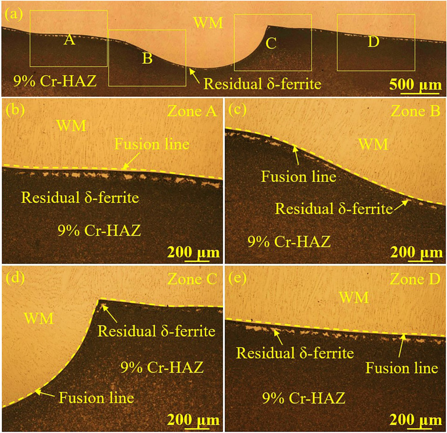
Figure 8 schematically illustrated the formation and distribution of the residual δ-ferrite in the multi-layer and multi-pass overlaying processes. The δ-ferrite formed initially at high temperature and remained in 9% Cr-HAZ along the fusion line after single overlaying, as shown in Figure 8(a). During multi-pass overlaying, the latter weld could impose the localised thermal effect on the previous one. Additionally, the 9% Cr-HAZ of the former and latter welds intersected with each other, as marked by the white dashed lines in Figure 8(b). Based on the heat effect caused by subsequent weld on previous HAZ, the intersecting region of contiguous HAZs was divided into three different zones, namely new formation zone (NFZ), transition zone (TZ), and unaffected zone (UZ) of the residual δ-ferrite. Similar to the single-layer overlaying specimen, the primary δ-ferrite formed by the thermal effect of the latter weld and then partially remained in the latter 9% Cr-HAZ adjacent to the fusion line, i.e. NFZ. The region marked with the red dashed lines in Figure 8(b) represented TZ with fewer residual δ-ferrite in the junction area of contiguous HAZs. The incomplete phase transition from residual δ-ferrite to austenite came from the additional thermal effect of the latter weld. In general, the occurrence of residual δ-ferrite was mainly determined by the time sustained in the temperature range where δ-ferrite phase was involved [28], including the liquid + δ-ferrite, δ-ferrite, and austenite + δ-ferrite phase fields. With the application of multi-layer multi-pass overlaying, the specimen suffered a longer time in the above-mentioned characteristic fields in comparison with those in the single-layer one. Thus, the diffusion time for compensating element segregation was longer, resulting in a larger transition tendency from the primary δ-ferrite to austenite. Consequently, a zone with reduced or absent residual δ-ferrite could be observed in 9% Cr-HAZ. As for UZ, the residual δ-ferrite exhibited unobvious change owing to the slight thermal effect by the subsequent weld. Meanwhile, for the multi-layer welding, a similar mechanism caused by the latter welding layer could lead to the partial phase transition of the residual δ-ferrite, as illustrated in Figure 8(c,d). As a result, the residual δ-ferrite distributed heterogeneously in 9% Cr-HAZ of multi-layer multi-pass overlaying specimen with a decreasing amount and size compared to the single-layer one.
Schematic for the formation and distribution of the residual δ-ferrite in 9% Cr-HAZ during (a), (b) multi-pass overlaying, and (c,d) multi-layer overlaying.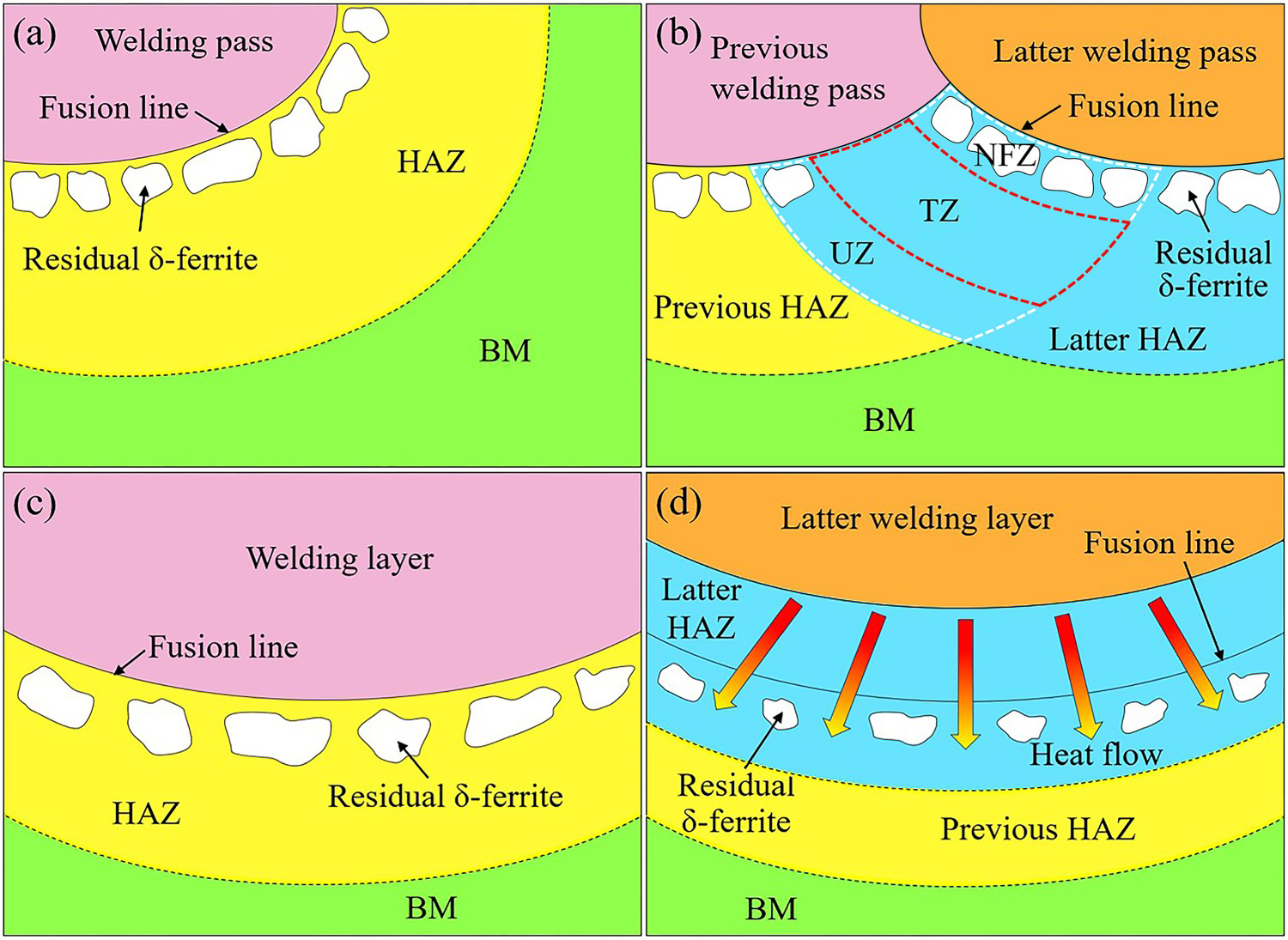
Control of the residual δ-ferrite in dissimilar welded joint
The excessive residual δ-ferrite usually had a negative effect on the mechanical properties of the welded joint and should be avoided. Based on the distribution of the residual δ-ferrite in Alloy 617/9% Cr dissimilar welded joint, the approach to control the residual δ-ferrite in 9% Cr-HAZ was further developed. In the case of the actual multi-layer multi-pass welding process, the filling welding dominated the main part of the WM, followed by the covering welding. Figure 9 displayed the OM images of the residual δ-ferrite in 9% Cr-HAZ. The contact length in the multi-layer and multi-pass welded joint was about 2 mm. The difference in amount and size of the residual δ-ferrite was detected between the covering welding region [zone A in Figure 9(b)] and filling welding region [zone B in Figure 9(b)]. Figure 9(c) revealed that the residual δ-ferrite distributed continuously along the fusion line in zone A. However, no residual δ-ferrite was observed in zone B, as exhibited in Figure 9(d).
OM images of Alloy 617/9% Cr dissimilar welded joint accompanied with multi-layer multi-pass welding method: (a) macrostructure of the overall welded joint, the weldment was cut into two parts to reveal the microstructure of each side; (b) microstructure of the specimen in the vicinity of the fusion line in 9% Cr side; (c,d) represents the distribution of residual δ-ferrite in the different regions of the welded joint.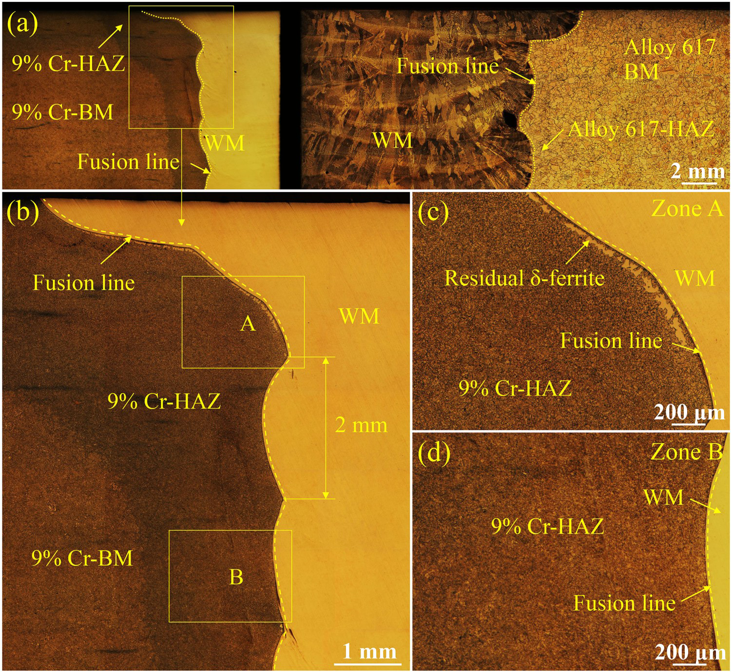
Figure 10 schematically illustrated the distribution of the residual δ-ferrite in 9% Cr-HAZ of the multi-layer multi-pass welded joint. Different welding operation could determine the segregation level of ferrite stabilising elements and time for the phase transition from δ-ferrite to other phases [29]. As displayed in Figure 10(a,b), for zone A, the heat effect from WM to BM during the welding process led to the formation of the residual δ-ferrite. With smaller thermal effect coming from a smaller contact area of each weld, less primary δ-ferrite was solidified at high temperature in zone B than that in zone A, as shown in Figure 10(c). Besides, the phase transition from δ-ferrite to other phases in zone B was promoted owing to the large intersecting HAZ formed by the contiguous two welds. Therefore, it was reasonable to conclude that the additional thermal effect resulted from the latter weld on the previous HAZ played a crucial role in the amount and size of residual δ-ferrite. The smaller thermal effect was generated in 9% Cr-HAZ during the multiple steps welding than that in the single-layer one owing to the shorter contact length. Additionally, the diffusion time for compensating element segregation could be regarded as the number of heat effects by the latter welding layers. Combined with the heat-affected region by the subsequent weld, it was found that the residual δ-ferrite in 9% Cr-HAZ experienced at least twice heat effects during the multiple steps welding. With the shorter contact length and longer diffusion time, there were fewer residual δ-ferrites existed in the multi-layer and multi-pass welded joint than those in the single-layer one. In particular, the formation of the residual δ-ferrite was anticipated to be controlled by choosing appropriate subsequent thermal input for Alloy 617/9% Cr dissimilar welded joint. The effect of δ-ferrite in the small covering welding region is temporarily not involved yet; however, further analysis of its effect on the mechanical property of welded joints is already in progress.
Schematic of the residual δ-ferrite and heat transition mode in 9% Cr-HAZ of Alloy 617/9% Cr dissimilar welded joint prepared by multi-layer multi-pass welding: (a) the overall welded joint; (b,c) the distribution of the residual δ-ferrite in covering welding region and filling welding region, respectively.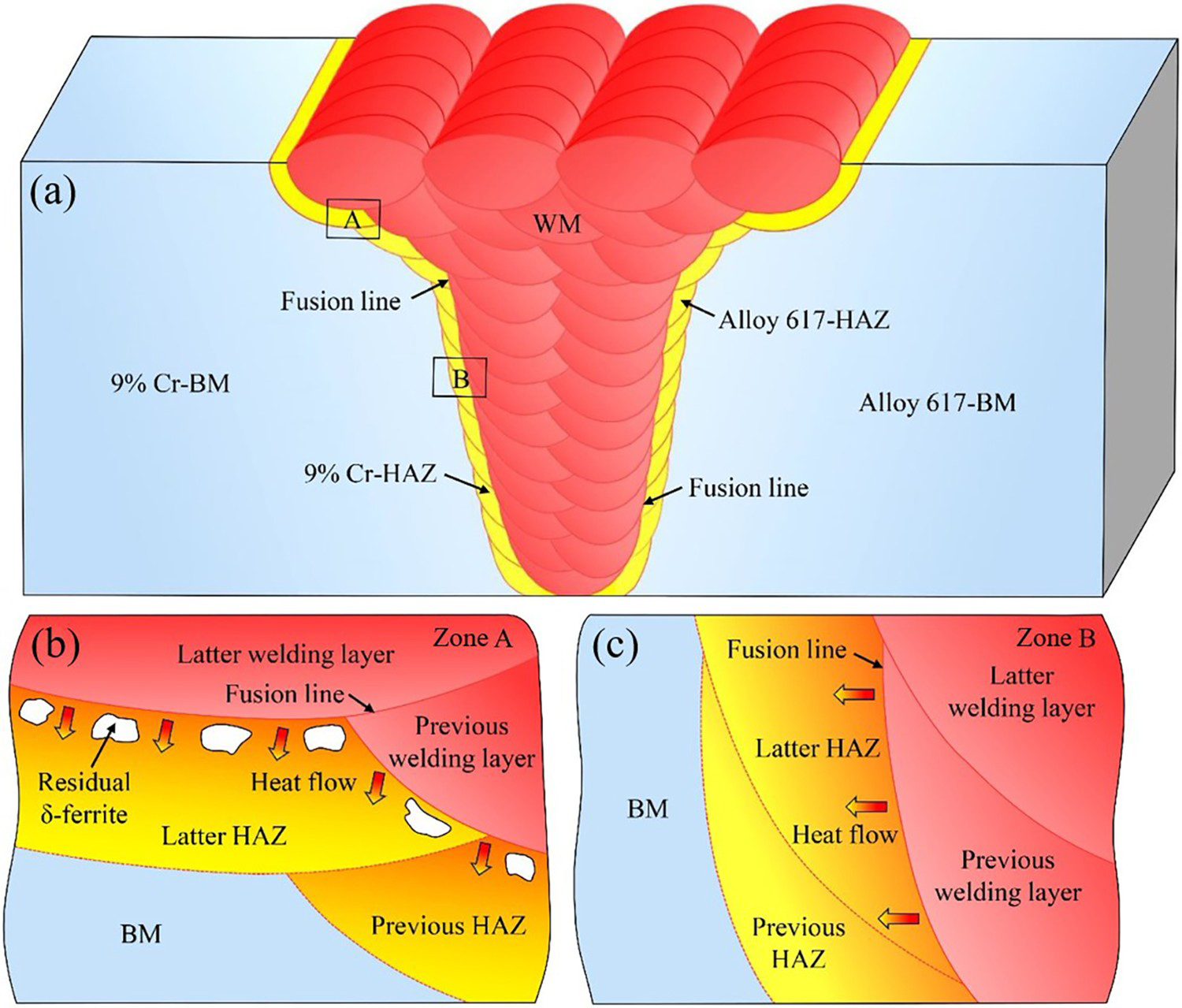
Conclusions
In this study, the formation and control of residual δ-ferrite in Alloy 617/9% Cr dissimilar welded joint manufactured by single-layer or multi-layer multi-pass welding technique were comparatively investigated. The main conclusions were listed as follows:
A special microstructure in patch shape was observed in 9% Cr-HAZ adjacent to the fusion line. The microhardness of these patches ranged from 175 to 188 HV while the surrounding martensite matrix possessed the microhardness 473–487 HV. The SEM image and EPMA result revealed that these patches were free from precipitates with the lower carbon content than the matrix. The special microstructure was identified as the residual δ-ferrite based on the microhardness test, microstructure features, and element distribution. Compared with the single-layer welded joint, the residual δ-ferrite in a less amount and a smaller size was detected in the multi-layer multi-pass overlaying specimen owing to the localised phase transition induced by the subsequent thermal effect on the previous HAZ. The contact length in the single-layer joint was about 9.2 mm and the 9% Cr-BM experienced the thermal effect once. The multiple steps welding had the shorter contact length (∼2 mm) and underwent at least twice the thermal effect. The diffusion time increased with the number of latter welding layers. The residual δ-ferrite existed in the single-layer specimen and covering welding region due to the large thermal effect. On the contrary, the change of heat transfer and resultant small thermal effect led to the absent of residual δ-ferrite in the filling welding region.
Footnotes
Disclosure statement
No potential conflict of interest was reported by the author(s).