
Abstract
The solidification cracking susceptibility of aluminium alloys 2024, 2219, 6061 and 7075 was evaluated recently by the transverse motion weldability test (the lower sheet moved in the transverse direction of lap welding to cause cracking). The tested welds were analysed in the present study. Their transverse cross-sections showed wide backfilled cracks in 2219 (least susceptible) and narrow open cracks in 6061 (most susceptible). Their fracture surfaces showed continuous eutectic in 2219 and discontinuous eutectic in 6061, consistent with the less backfilling in 6061. T was plotted against (fS)1/2 (T: temperature; fS: fraction solid) to explain the differences. The critical local strain rate near the crack was estimated, significantly lower in 6061 than 2219 and consistent with the higher crack susceptibility of 6061.
Keywords
Introduction
Solidification cracking is caused by tension induced by solidification shrinkage and thermal contraction during welding [1, 2]. As illustrated in Figure 1, Kou [3] considered three factors at the grain boundary during cracking. Factor 1 is the lateral separation of grains by tension to cause cracking, Factor 2 the lateral growth of grains toward each other to bond together to resist cracking and Factor 3 liquid feeding along the grain boundary to resist cracking. Consider the volume element Ω between the roots of two grains. If the rate of Ω increase by Factor 1 exceeds that of Ω decrease by Factor 2 and that of Ω decrease by Factor 3, cracking can occur. Kou [3] showed the radius of the dendrite roots R is proportional to (fS)1/2, where fS is the fraction solid. If |dT/dR| is small, i.e. the lateral growth dR is small for a given temperature drop |dT| during cooling, lateral growth is slow and Factor 2 is small. Since the dendrites hardly grow thicker as they grow longer, the liquid channels between dendrites become long to resist feeding [4] and decrease Factor 3.
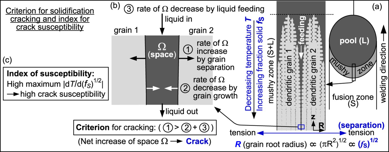
Thus a high |dT/dR| and hence a high |dT/ d(fS)1/2| near (fS)1/2 = 1.0 suggests a high crack susceptibility. Since the maximum |dT/d(fS)1/2| often occurs near (fS)1/2 = 1.0, Kou [5] considered the maximum |dT/d(fS)1/2| as an alternative to |dT/d(fS)1/2| near (fS)1/2 = 1.0. Fisher and Kurz [6] and Rappaz et al. [7] showed at fS = 0.98 or (fS)1/2 = 0.99 dendrites appear to be well bonded together, no longer susceptible to solidification cracking. Thus Kou [5] suggested the maximum |dT/d(fS)1/2| up to (fS)1/2 = 0.99 as the index for the susceptibility of Al alloys to solidification cracking. The index showed good agreement with results of solidification cracking tests and filler metal guides [3, 5, 8-16]. Kun and Kou [17] showed that the index also worked well for Mg alloys.
Figure 2 shows the Transverse Motion Weldability (TMW) test developed by Soysal and Kou for Al alloys [18-20] and also applied to Mg alloys [17]. The lower sheet moves in the transverse direction of lap welding to induce tension and cause cracking. Unlike the Varestraint test [21], tension can be applied slowly, and a filler wire can be used. This study examined the microstructure of Al alloys 2024, 2219, 6061 and 7075 in the TMW test [19] and used it to explain the relative crack susceptibility evaluated, determine the local critical strain rate near the crack and compare the rate with the evaluated susceptibility.
Transverse motion weldability (TMW) test developed by Soysal and Kou [19].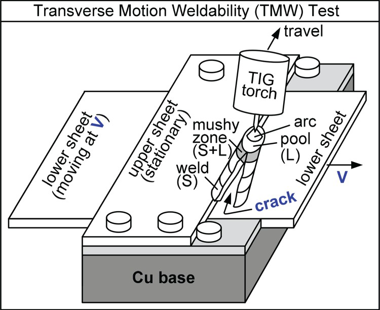
Experimental procedure
The TMW test was conducted by gas-tungsten arc welding (GTAW or TIG) on sheets of Al alloys 2024, 2219, 6061 and 7075. The lower sheet was 3.2 mm thick, 102 mm wide and 127 mm long, and the upper sheet 3.2 mm thick, 152 mm wide and 51 mm long. Lap welding was conducted in the width direction. The following welding conditions were used: AC polarity with 70% balance (70% negative and 30% positive polarity), 160 A current, 2.1 mm/s welding speed, 3.54 × 10⁻⁴ m3/s (45 cfh) Ar shielding gas, and 3.2 mm diameter tungsten electrode with 15o electrode tip angle. The areas near the expected welding pass were cleaned with steel brush and acetone before welding [19].
In the TMW tests of Al alloys 2024, 2219, 6061 and 7075 [19], about eight welds of each alloy were made, each weld made at a different speed of the lower sheet V. As V increased, the crack length increased from zero to the full length of the weld. The first weld to reach the full crack length was selected, cut in the transverse direction in the middle, polished and etched for microstructural examination. For convenience of discussion, the V of this weld will be called the critical lower sheet speed Vc. The first weld in which cracking occurred was not selected because it could have any crack length and a consistent location could not be selected for microstructural examination. 2219 Al and 2024 Al were etched with 0.5% HF in distilled water, and 6061 Al and 7075 Al with Keller's etching solution (5 mL HNO3, 3 mL HCl, 2 mL HF and 190 mL distilled water). The microstructure was examined by optical microscopy and scanning electron microscopy (SEM).
In the transverse optical micrograph of each alloy, the width of the narrow region D showing minor cracks next to the main crack was measured. Vc was divided by D to determine the critical strain rate near the crack,
 , as will be explained subsequently.
Results and discussion
Backfilling of cracks
Figure 3 shows the transverse cross-section of the 2219 Al weld made at Vc = 0.20 mm/s. Minor cracks are visible on either side of the main crack. Some cracks are very wide and backfilled as shown in Figure 3(d). The composite-like phase in the crack is the Cu-rich eutectic. The wide backfilled cracks suggest plenty of liquid near the end of solidification and wide liquid channels between columnar grains easy for backfilling.
2219 Al transverse cross-section: (a and b) optical macrographs; (c and d) SEM images. V = 0.20 mm/s. Width of region of high strain (minor cracks): 911 µm (sum of lengths of top two white lines), 760 µm (middle) and 901 µm (bottom). Average D = 857 µm.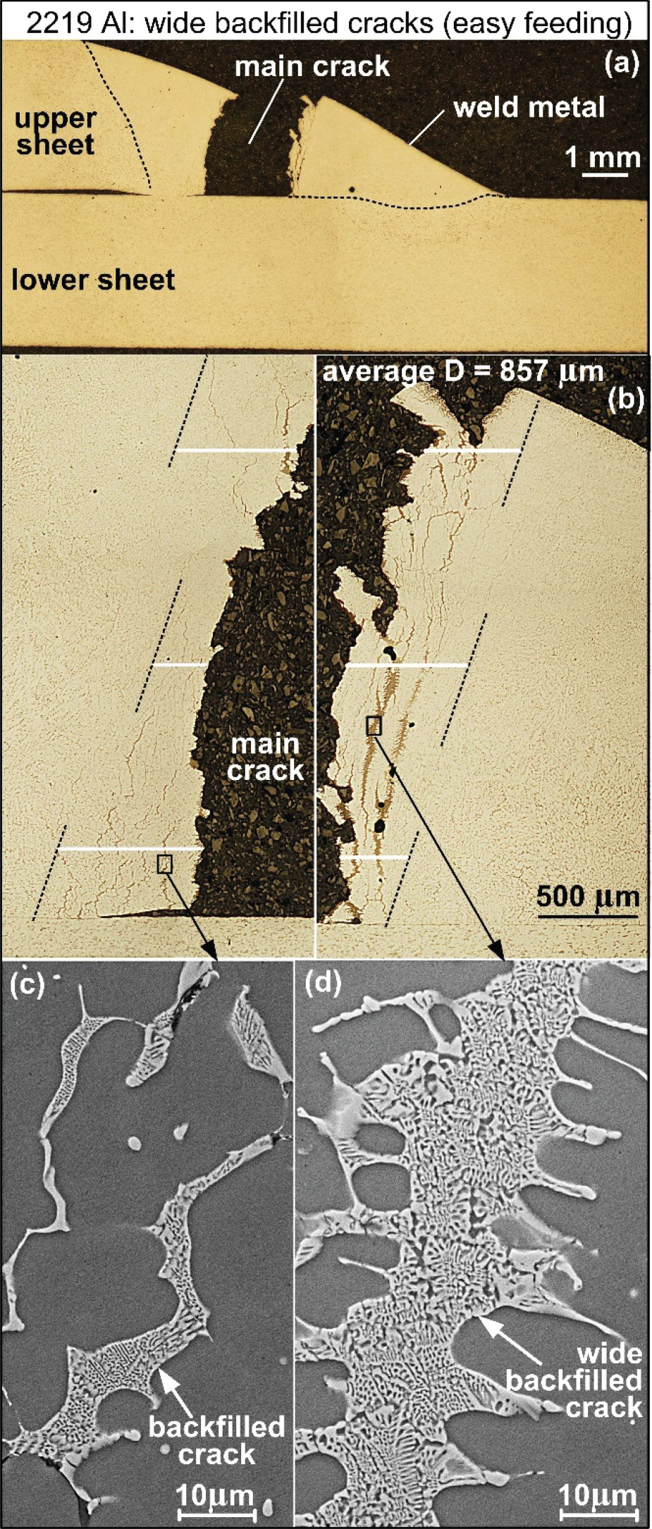
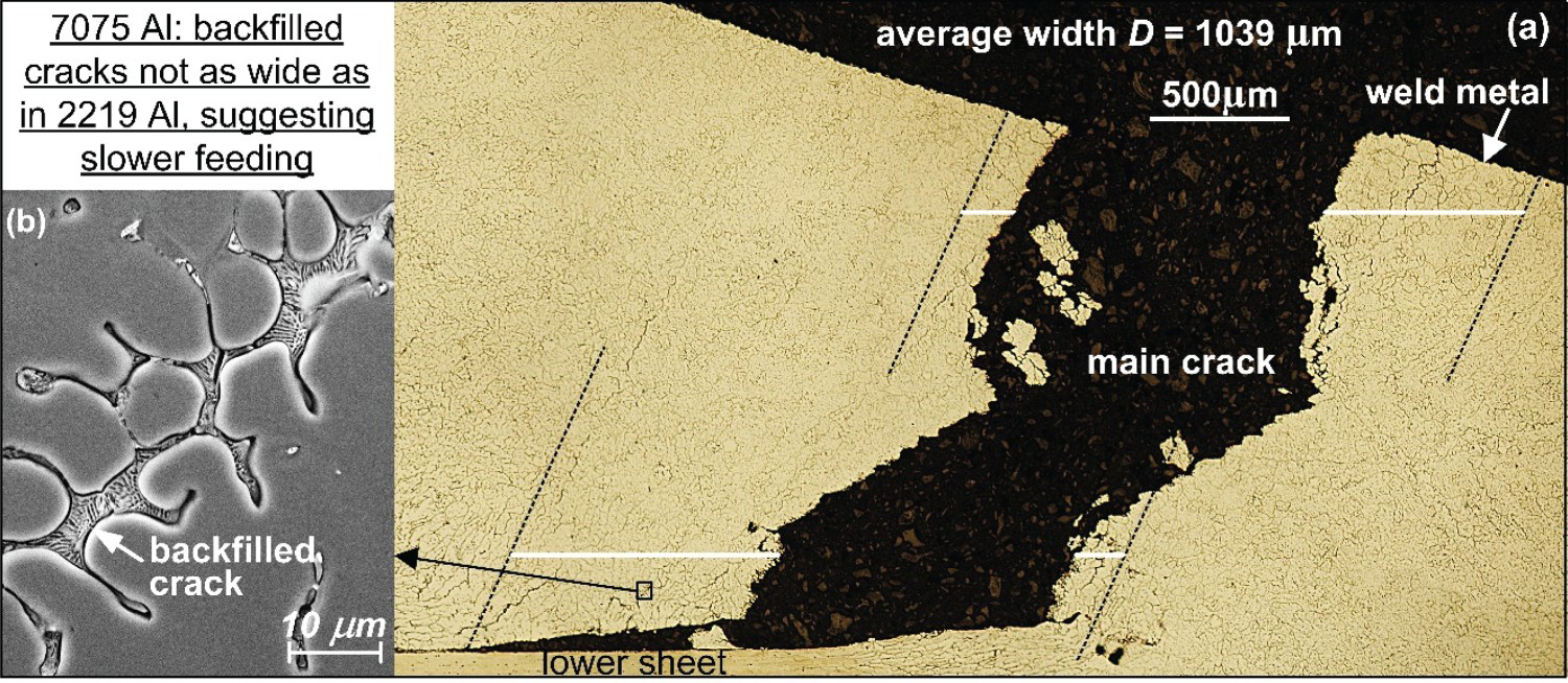
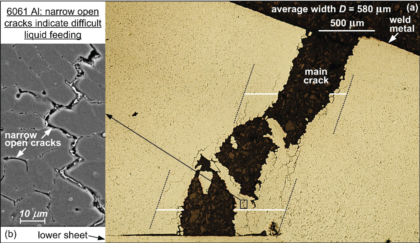
Like 2219 Al, almost all cracks in 2024 Al and 7075 Al were backfilled. As shown in Figures 4 and 5, the widest backfilled cracks are significantly narrower than those in 2219 Al, suggesting liquid channels were narrower than those in 2219 Al. As shown in Figure 6 for 6061 Al, the widest cracks are even narrower and are either partially backfilled or mostly open. This suggests very narrow liquid channels in 6061, difficult for feeding.
2024 Al transverse cross-section: (a) optical micrograph; (b) SEM image. V = 0.15 mm/s. 7075 Al transverse cross-section: (a) optical micrograph; (b) SEM image. V = 0.10 mm/s. 6061 Al transverse cross-section: (a) optical micrograph; (b) SEM image. V = 0.05 mm/s.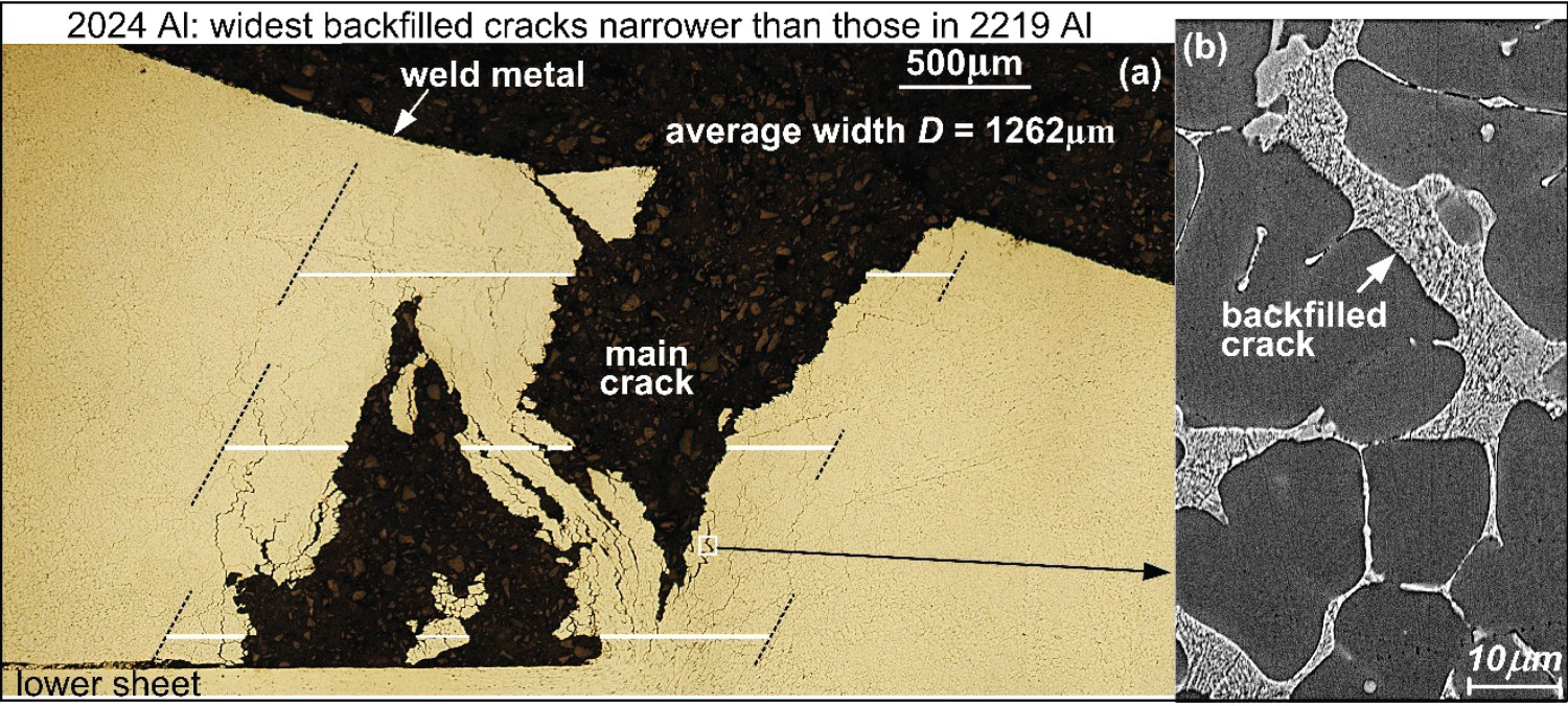
Fracture surfaces
The dendritic fracture surfaces in Figure 7 confirm solidification cracking. When cracking occurred, most of the eutectic grain boundary liquid immediately pulled back from the surfaces of the bumps (secondary arms) to the surfaces of the nearly flat bases (primary arms). This occurred because of the minimisation of the surface area and hence the surface energy. The eutectic on the bases is continuous, especially in 2219 and 2024. However, it is discontinuous in 6061, where regions of naked bases are visible in Figure 7(d), correspond to the narrow open cracks shown in Figure 6(b).
SEM images of fracture surfaces: (a) 2219; (b) 2024; (c) 7075; (d) 6061.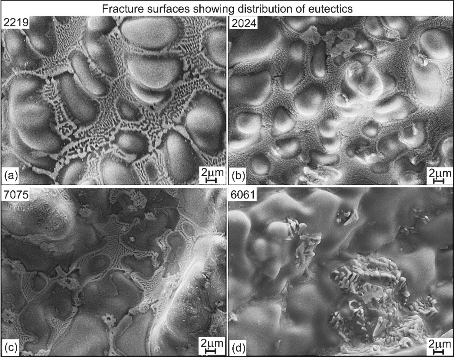
Explanation for crack susceptibility and backfilling
Since the dendrite root radius R is proportional to (fS)1/2and since temperature T increases with increasing axial distance z, the outer contour of a columnar dendritic grain during terminal solidification can be represented by the curve of T vs. (fS)1/2 [3, 5]. The T-(fS)1/2 curves in Figure 8, calculated using Pandat [22] and PanAl [23] assuming Scheil solidification [1, 2], show widest shortest liquid channel in 2219, easiest for liquid feeding, and narrowest longest ones in 6061, most difficult for liquid feeding. This is consistent with the change from the wide backfilled cracks in 2219 to the narrow open cracks in 6061 shown in Figures 3–6.
Curves of T vs. (fS)1/2 showing liquid channels between grains, from wide short channel easy for feeding in 2219 to narrow long channel difficult for feeding in 6061, consistent with wide backfilled cracks in 2219 Al (Figure 3) and narrow open cracks in 6061 Al (Figure 6). Steepness of tangent (white dotted line), i.e. predicted crack susceptibility, is in the order of 2219 < 2024 < 7075 < 6061.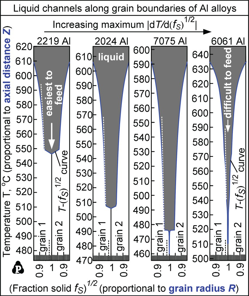
Critical strain rate near crack
When the critical strain rate is exceeded, solidification cracking can occur. The critical strain rate is not an intrinsic property of an alloy. It can be affected by sheet thickness, welding conditions, and whether filler metal is used. Yet, in-situ observation and measurement during welding have been developed to determine the critical strain rate [24-28], even with advanced hardware and software [29, 30]. In view of this significant interest, the possibility of estimating the critical strain rate using welds in the TMW test of Al alloys was explored.
As already shown in Figures 3–6, numerous minor cracks tend to exist in a narrow region in the weld metal next to the main crack but not elsewhere in the bulk weld metal. This suggests nonuniform tensile strain in the mushy zone, highest in the narrow region just before cracking occurs. Thus, as illustrated in Figure 9, the critical local average strain rate near the crack can be expressed as follows:
Critical strain rate within the mushy zone near the crack.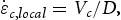
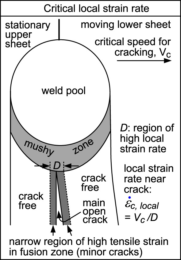
Taking 2219 Al in Figure 3 as an example, V = Vc =0.20 mm/s. At each level D is represented by the sum of the lengths of two white horizontal lines, i.e. 911, 760 and 901 µm. The average D is 857 µm and
 = Vc /D = 0.233/s or 23.3%/s. For 2024 Al in Figure 4, Vc = 0.15 mm/s. The fine cracks more parallel to V than normal might be caused by the bridge across the main crack and thus are not considered. The average D is 1.262 mm and
 = Vc /D = 0.119/s. For 7075 Al in Figure 5, Vc = 0.10 mm/s and D is 1.039 mm, thus
 = Vc /D = 0.096/s. As for 6061 Al in Figure 6, Vc = 0.05 mm/s and D is 0.580 mm, thus
 = Vc /D = 0.086/s.
Figure 10 shows
 in the order of 2219 Al > 2024 Al > 7075 Al > 6061 Al, just like Vc in the TMW test [19]. The lower the
 or Vc is required to cause cracking, the higher the crack susceptibility is. Thus the crack susceptibility is in the order of 2219 < 2024 < 7075 < 6061. In Figure 8, the steepness of the tangent (white dotted line) represents the crack susceptibility index, i.e. the maximum |dT/d(fS)1/2| up to (fS)1/2 = 0.99. It is 1649°C for 2219, 3309°C for 2024, 4152°C for 7075 and 4848°C for 6061 [5]. Thus the predicted crack susceptibility is in the order of 2219 < 2024 < 7075 <6061. Thus for Al alloys the examination of the microstructure near the main crack in the TMW test may be a simple alternative to in-situ observation for determining the critical strain rate.

Conclusion
Microstructural analysis of Al welds in the TMW test has shown wide backfilled cracks in 2219 consistent with its low crack susceptibility and narrow open cracks in 6061 consistent with its much higher crack susceptibility. The T-(fS)1/2 curves near (fS)1/2 = 1 show in 2219 wide short liquid channels between grains easy for liquid feeding and in 6061 narrow long channels difficult for liquid feeding. The tensile strain inside the mushy zone is not uniform but much higher in the narrow region near the crack where minor cracks exist. The critical local strain rate, approximated by
 = Vc/D, has been found much higher in 2219 (23%/s) than in 6061 (9%/s), consistent with the much lower susceptibility of 2219 than 6061 in the TMW test. Since the critical local strain rate is not an intrinsic property of an alloy, these strain rates are relevant only to welding conditions and workpiece dimensions involved in the present study.
Footnotes
Disclosure statement
No potential conflict of interest was reported by the author(s).