
Abstract
This paper investigates the influence of collision angle on the interface characteristics and mechanical properties of magnetic pulse welded AA4014 tubes/Cu rods. It is shown that the collision angle, which affects the collision velocity, plays a crucial role in controlling the thickness of intermetallic compounds (IMC) layer and defect formation at the weld interface. The creation of a thin and continuous IMC layer at the weld interface is responsible for the higher load-bearing capacity of the sample welded under a collision angle of 4°. The welds made at higher collision angles are featured by a thick IMC layer containing defects such as micro-cracks, pores and cavities, which reduced the load-bearing capacity of the joint.
Keywords
Introduction
Dissimilar welding of aluminium to copper provides crucial opportunities for power generation, electronics and transportation industries by combining the improved mechanical, thermal and electrical properties of the copper with the low density and cost of the aluminium [1, 2]. Owing to tremendous differences between thermal, metallurgical and mechanical properties of aluminium and copper, welding these metals using conventional welding methods is not practical. The formation and growth of intermetallic compound (IMC) at the interface is the critical metallurgical challenges during dissimilar Al/Cu welding. The brittleness of IMC coupled with the presence of internal stress created during the thermal joining process due to large differences between thermal properties of Al and Cu makes their dissimilar joint very susceptible to cracking and brittle failure during loading [3-6]. This challenge prevents successful fusion welding of the Al/Cu combination. This problem can be minimised by using solid-state welding processes [7]. For example, there are some reports on successful dissimilar Al/Cu joining using ultrasonic welding [8] and friction (stir) welding [1, 9, 10]. However, making tubular welded joints (e.g. tube to rode welding) using these processes is challenging to set up. Magnetic pulse welding (MPW) as a solid-state high-velocity impact welding process provides a further opportunity for fast welding of dissimilar Al/Cu combination. The superior asset of MPW as a cold welding process is that it can minimise the formation of intermetallic compounds by lowering the time and temperature of interaction between two metals during the welding process [11]. Moreover, electromagnetic force can be directed with precision resulting in minimum distortion of original part dimensions [12].
Recently, several studies have been conducted to investigate the effect of the MPW parameters on the microstructures and mechanical properties of dissimilar Al/Cu joints. Raoelison et al. [13] joined Al tubes to copper rods. They showed that with increasing input voltage in the initial gap, the thickness of the IMC layer at the interface is improved. Besides, with the increase of the initial gap, more transverse micro-cracks are formed across the intermetallic layer, which leads to random fracture at the welded interface. Itoi et al. [14] welded Al sheets to Ni-coated Cu sheets and indicated that with increasing discharge energy, the volume fraction of the intermediate layer is increased. Further, the presence of Ni fragments in the IMC layer was attributed to localised melting and rapid solidification of molten Ni during the welding process. Faes and Kwee [15] reported that the change of the morphology at interface of Al1050/Cu sheet joints is related to the continuous variation of the impact velocity and impact angle. Moreover, hardness at the interfacial layer is higher than that of the base materials because of the phase transformations. Also, high tensile forces are obtained at higher discharge energies and lower stand-off distances. Wang et al. [16] reported that an inhomogeneous layer of intermetallic compound is formed in the different welding regions of Al–Cu joints. They found that temperature and pressure are important parameters which determine the phase stability of intermetallic compounds. Sarvari et al. [17], in their work on the dissimilar welding of Al/Cu sheets, reported that the collision angle could affect morphology and waviness of the weld interface.
Although dissimilar joining of aluminium and copper using MPW has been investigated, the influence of collision angle on the interface morphology and mechanical properties of tubular joining have been inadequately investigated in the previous works. Therefore, the aim of this work is to investigate the effect of collision angle during MPW on the joint interface microstructure and mechanical properties of tubular AA4014 Al alloy to copper.
Experimental methods
Equipment setup
In this work, a 10-kJ magnetic pulse welding apparatus made by the Shetabgaran Fanavary Golestan Company was utilised. The range of discharge voltage was from 3 to 11 kV, and the maximum discharge frequency was 18 kHz. Two capacitors with a capacitance of 150 µF were connected in a parallel design. A 6-turn solenoid coil made of pure copper was employed. The diameter and length of the coil were 20 and 30 mm, respectively. Figure 1(a) shows the position of flyer and target metals inside the coil and Figure 1(b) represents the joining assembly.
(a) Position of flyer and target metals inside the coil and (b) representation of the tubular joining assembly.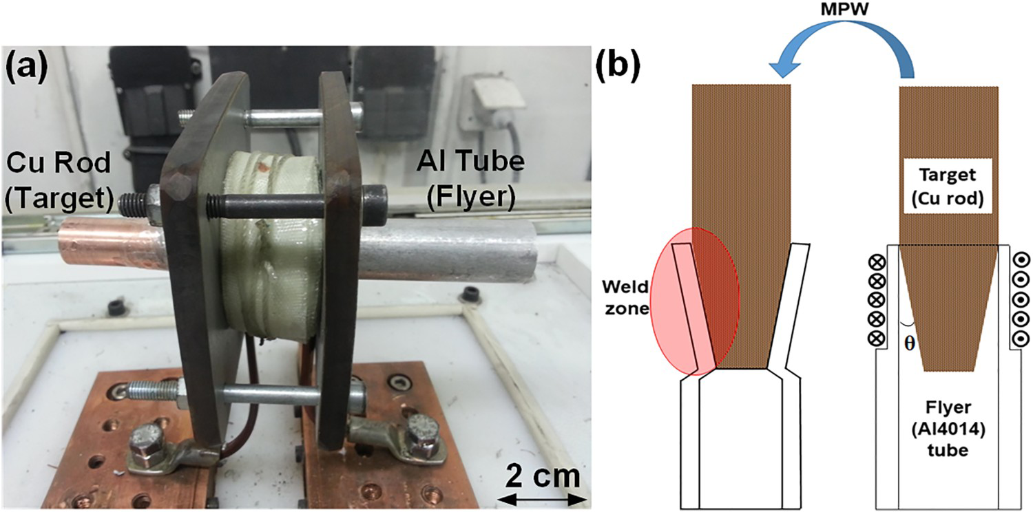
Weld specimens and parameters
AA4014 aluminium alloy tube as moving metal and Cu (99.9% pure) rod as target metal were selected for the experiment. AA4014 tubes had an inner diameter of 16 mm, an outer diameter of 20 mm and a length of 50 mm. The size of Cu rods was 20 mm in diameter and 70 mm in length. The thickness of the first 30 mm of the flyer length was reduced from 2 to 1 mm by the machining process. Welding tests were carried out using a constant charging voltage of 8 kV with different initial collision angles. Conical target parts were prepared to set the collision angle in the range of 4°, 8° and 12°. Because of the conical collision angle, the increase of stand-off distance between the inner rod and the outer tube occurred during the welding process [18].
Structural and mechanical characterisations
The cross-section of welded samples was investigated after cutting along the axial direction of the weld area. The microstructure of the weld interfaces was inspected by an optical microscope (OM) and scanning electron microscopy (SEM). A Vickers microhardness tester was utilised to measure the hardness of the weld interface. The mechanical strength of the welded specimens was measured by a tensile tester machine using a specially designed fixture.
Results and discussion
The microstructure of weld interfaces
The collision angle affects the collision velocity, which in turn controls the interface temperature [19]. Increasing the collision angle increases the collision velocity causing the increase of the joint interface temperature [20]. The interface temperature controls the microstructure evolution and defect formation at the joint interface. In this section, the effect of the collision angle on the interface microstructure is investigated.
Figure 2 shows the interface morphology of the welded sample under a collision angle of 4° and a charging voltage of 8 kV. A wavy interface with small waves and a thin IMC layer at the onset of the weld zone is observed (Figure 2a). It is well established that the IMC layer is mainly composed of Cu2Al phase [13, 21]. It can also be seen that the thickness of the intermetallic compound layer is increased in the middle of the weld interface and reaches about 20 µm (Figure 2b). Finally, towards the end of the weld zone, a small wavy interface with thin and dispersed intermetallic pockets is observed (Figure 2c).
Morphology of Al/Cu joint interface from the start to the end of the welded zone under various collision angle of (a–c) 4°, (d–f) 8° and (g–i) 12°.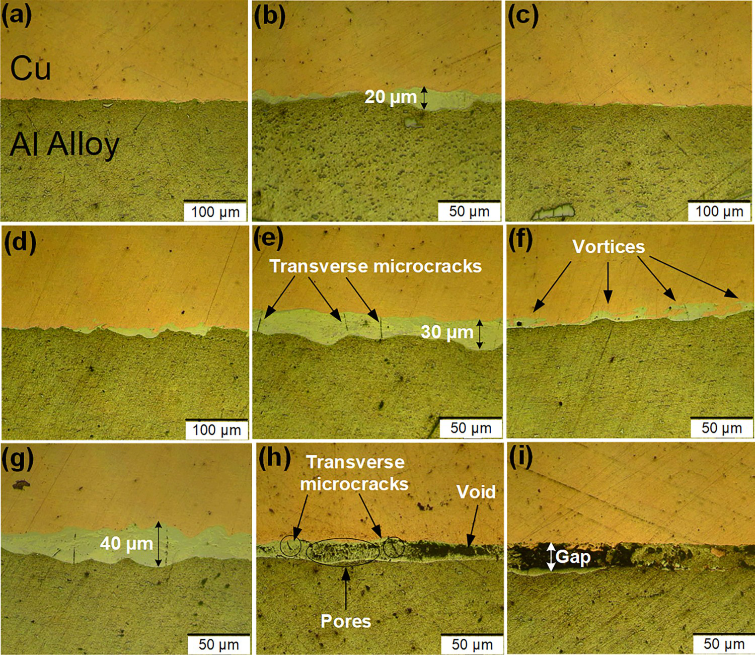
With the increase of the collision angle to 8°, it is observed that the IMC emerges at the start of the weld zone (Figure 2d). Also, the thickness of the IMC layer is significantly increased along the middle zone, which has a wavy morphology. The thickness of the intermetallic layer changed from a few micrometres to about 30 µm. Some transverse micro-cracks appeared within the IMC layer (Figure 2e). The formation of transverse micro-cracks in the IMC layer can be explained as follows. When most of the kinetic energy of moving metal is transformed into the heat in the contact zone, the temperature locally rises at the weld interface. It causes that temperature becomes higher than that of the melting point of one of the parent metals, and consequently melting happens [20]. Moreover, because of a high-temperature gradient between two metals, high thermal stress and huge plastic deformation, tensile stresses are extended during cooling. They might become more elevated than the strength of the intermetallic phase. Therefore, cracking of IMC layer can occur [22]. Near the end zone, a wavy interface associated with several vortices is revealed at the interface (Figure 2f). The vortex zone consists of an IMC in whorled shape. The vortex phenomenon has been defined by the Kelvin–Helmholtz instability mechanism [23]. According to this model, if two materials with various horizontal velocities collide together, instabilities will be created as a consequence of interferences. The instability with a direction and specified energy causes motion of material from one side of the interface to the other, and instantly a motion of material from the other side back for complementing the energy. This condition generates a mass flow from the higher density material to the lower one. This whirling kinematic flow forms the vortex, which has its characteristic direction. The weld interface twists and rolls inside the vortex area, which can lead to the local melting of metals induced by intense plastic deformation. The IMC observed at the vortex location is typical evidence of such melting in the restricted region [4, 23]. It is of note that the waviness of the joint interface is increased by increasing the collision angle from 4° to 8°. It has been reported that when collision velocity rises, the probability of occurrence of transition from straight to wavy interface with vortices increases [24].
The interface of the welded sample under a collision angle of 12° is a wavy interface with a continuous intermetallic layer at the start zone of the weld (Figure 2g). The maximum thickness of the intermetallic phase is increased to 40 µm. It is followed by a porous structure with accidentally dispersed porosities in various sizes at the middle zone. Additionally, the number of micro-cracks that are confined at the interface is increased with the increase of the intermetallic phase thickness. Subsequently, pores coalescence leads to the formation of voids (Figure 2h). These voids become more significant in the end zone of the interface, which is like a gap between two metals (Figure 2i). The formation of the porous structure at the welding interface can be related to the dissolution of gases [25] as a result of a very high collision velocity, which causes a local rise of temperature at the weld interface. Hence, melting can occur.
Moreover, gases may trap and nucleate into gas bubbles and spread with the rapid solidification rate of the molten region. It can be concluded that due to intense pressure in the MPW process, the Al part of the intermediate phase can vaporise at temperatures less than vaporisation temperature [25]. Consequently, the radial growth of vaporised pores can result in the spherical shape of the porosities [19]. The other mechanism is associated with the cavitation phenomenon. Whenever a liquid phase is exposed to rupture tensions, a hole is formed. This can happen during the beginning of shrinkage due to the temperature decrease before the solidification. Then, the nucleation and coalescence of bubbles with the increase of tension level will take place [26].
Figure 3(a) shows the SEM micrograph of the weld interface under the collision angle of 12°, which reveals the network of micro-cracks inside the intermetallic inclusion. The formation of a surface micro-cracks network can be attributed to the ultra-rapid solidification of the molten layer, which can be considered as an indication for large tensile stress and high brittleness of these areas [27]. Figure 3(b) exhibits two kinds of cracks that are formed at the weld interface during welding. The number of cracks formed in the joint interface of welds made using a collision angle of 12° is higher than that of welds made using a collision angle of 8°. The tensile wave intensity depends on the kinetic energy loss at the interface upon collision, which is disclosed in the form of plastic deformation and shock wave. Thus increasing the collision angle leads to an increase in the collision velocity, which raises the energy of the tensile wave. Consequently, more cracks can be formed at the interface. According to Figure 3(b), the cracks have two morphologies: the plane cracks and the transverse cracks caused by the tensile wave. The plane cracks are situated parallel to collision direction, whereas the transverse cracks are formed perpendicular to impact direction. The plane cracks emerge like a continuous void layer that shows ordered or disordered gaps. Both types of these cracks are limited to the intermediate zone and do not propagate across the base materials, either in the copper rod or in the aluminium tube.
SEM micrographs of sample welded under collision angle of 12°: (a) network of micro-cracks inside the intermetallic region and (b) plane and transverse cracks at the welded interface.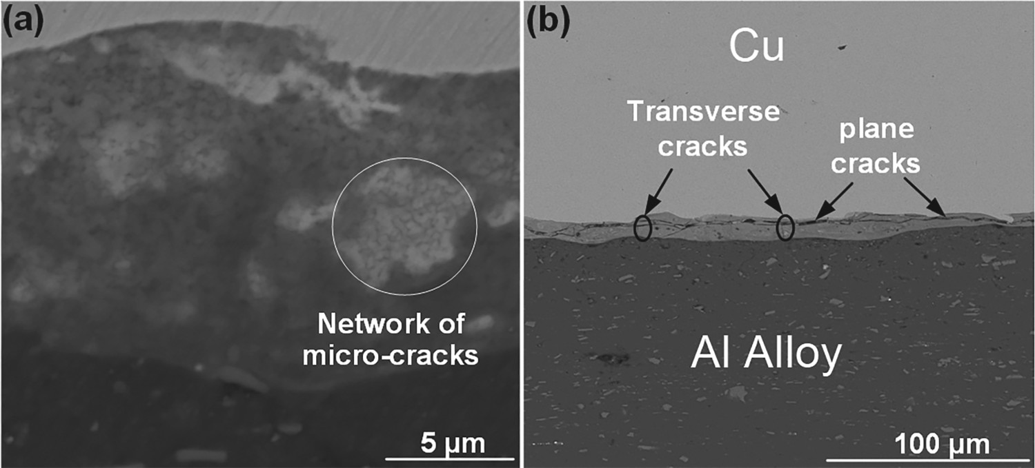
Microhardness
Figure 4 represents the microhardness imprints of the weld interfaces and base metals for two different collision angles. The hardness of the intermediate phase is higher than those of Al and Cu. The measured hardness values of intermediate phases for collision angles of 4° and 12° are 231 and 381 HV, respectively. The high hardness of the interfacial layer can be related to the formation of brittle intermetallic compounds at the weld interface [13, 21, 26, 28]. Moreover, the fine grained microstructure of the interface layer is also reported as a reason for high hardness of the interfacial layer [28].
Microhardness indentations in the intermetallic compound layer and the base metals of two interfaces welded under collision angles of (a) 4° and (b) 12°.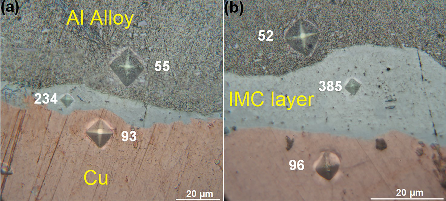
Weld strength
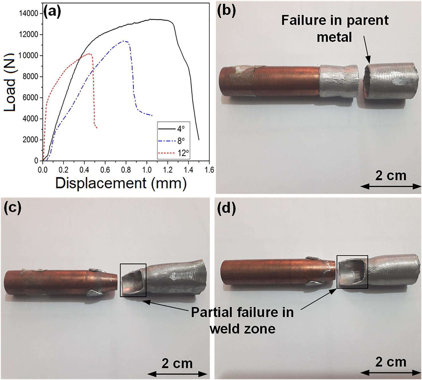
Figure 5(a) illustrates the load–displacement curves of the welded samples. The welds made at a collision angle of 4° exhibited the highest load-bearing capacity. In the welded sample under a collision angle of 4°, failure occurred in the aluminium tube during the tensile test (Figure 5b). Therefore, it can be inferred that this joint has adequate strength. This is a function of the formation of a thin, continuous and defect-free IMC layer. However, increasing the collision angle beyond 4° decreases the joint peak load. The failure of joint made at a collision angle of 8° and 12° occurred partially through the joint interface (Figure 5c and d). The reduction of the load-bearing capacity of welded joint at higher collision angle can be related to several factors:
Increased thickness of the IMC layer: According to Figure 2, the maximum width of the IMC layer increased from 20 to 40 by increasing the collision angle from 4° and 12°. The presence of a thick IMC layer provides a low-fracture toughness easy crack growth path along the interfacial layer, which is accompanied by a lower failure load. Formation of micro-cracks in the IMC layer: According to Figure 2, the micro-cracks are formed in the IMC layer in welds made using a collision angle of 8° and 12°. These micro-cracks facilitate the failure process. Formation of voids, pores and un-bonded zones at the joint interface: According to Figure 2, at a collision angle of 12°, a significant amount of voids and pores are formed in the interfacial layer. Moreover, there are some un-bonded zones at the joint interface. For collision angles of 4°and 8°, the joint is continuous, and the length of the bonding zone is almost 2 cm. However, for a collision angle of 12°, since there are gaps at the interface, the joint is discontinuous, and the weld length is shorter (about 1.5 cm). The presence of voids, pores and un-bonded zones reduces the effective load-bearing area and hence results in reduced joint strength. (a) Load–displacement curves of Al/Cu magnetic pulse welded samples at various collision angles, welded samples after the tensile test for collision angles of (b) 4°, (c) 8° and (d) 12°.
It is of note that increasing the collision angle increases the waviness of the joint interface. A wavy interface can enhance joint strength by improving the mechanical interlocking [7]. However, as it is seen in this work, the formation of a high-amplitude wavy interface is associated with higher interface temperature, which promotes the creation of a defective joint interface with a thick IMC layer.
According to the results presented in this paper, the collision angle plays a crucial role in controlling the interface temperature, IMC thickness, interface waviness, defect formation, and hence the joint strength during MPW of Al/Cu dissimilar weld.
Conclusion
In this work, the MPW technique was successfully conducted to join AA4014 tubes to Cu rods. It is shown that controlling the collision angle is critical to achieving a strong metallurgical bond. The weld made at collision angle to 4° exhibited the highest load-bearing capacity, and the failure occurred outside of the joint interface at the aluminium tube. However, welds made at collision angles of 8° and 12° were featured by a decreased load-bearing capacity, and their failure occurred partially in the weld zone. The decrease in peak load of the welds made higher collision angles was a function of increased thickness of the intermetallic layer, the formation of micro-cracks in the intermetallic layer, and the formation of the un-bonded zone at the joint interface.
Footnotes
Disclosure statement
No potential conflict of interest was reported by the author(s).