
Abstract
This work aims to study the microstructure and mechanical properties of stainless steel/carbon steel clad plate joints with three welding types: welding without transition layer, welding with transition layer using tungsten inert gas arc welding and shielded metal arc welding, respectively. Both of transition layer-weld metals contain ferrite + austenite phases obtained by different solidification modes. The brittle martensite zone is formed in the stainless steel weld metal without the transition layer because of the excessive diffusion of Cr, Ni elements. The clad plate joints with transition layer welded by shielded metal arc welding achieved the best welding quality without excessive alloy element dilution or formation of brittle phase, which reveals a perfect welding joint without obvious hardness gradient and obtains outstanding mechanical properties.
Keywords
Introduction
Stainless steel clad plate consisting of carbon steel substrate and stainless steel cladding has widespread met the increasing demand for industrial applications, especially due to its excellent weldability, high corrosion resistance and superior mechanical properties [1-4]. Meanwhile, it saves the expensive strategic Cr and Ni elements and reduces the fabrication cost, offering a wide range of development prospects [5, 6]. Welding of stainless steel clad plate is an indispensable process to fabricate separators, pressure vessels, pulp digesters, heat exchanger shells and tube plates in gas, petrochemical industry and other fields [7-11]. Moreover, stainless steel clad plate often forms defects and cracks during the manufacturing or service process, which should be repaired by multiple welding to guarantee the integrity, safety and lifetime of the equipment [7, 12].
However, the welding of stainless steel clad plate is much more complicated in operation technology and bonding behaviour than traditional materials, which is attributed to the large differences in chemical composition, microstructure, mechanical and physical properties between the substrate and the cladding metals [13]. Thus, the weld joint between carbon steel and stainless steel behaves plenty of welding defects during the welding process. The excessive alloy elements (Cr, Ni) diffusion from stainless steel weld metal (SSWM) to carbon steel weld metal (CSWM) causes the excessive dilution of alloy elements as well as the disappearance of δ-ferrite in the SSWM zone near the welding interface, which degrades the mechanical properties and corrosion resistance of weld joints [14]. In addition, the following reacted hard and brittle phases are harmful to the mechanical and physical properties of the welding joint. For example, Hajiannia et al. [15] and Venkateswara et al. [16] found that the excessive alloying element diffusion resulted in the formation of Cr3C7 and Cr23C6 carbides at the welding interface, leading to the severe intergranular Cr-depletion and intergranular cracks. Moreover, the high welding heat input always introduces the formation of a large amount of hard martensite phase on the weld metal (close to the fusion line), resulting in severe microstructure and hardness gradients. This phenomenon may lead to crack initiation and in-service failure [17]. Therefore, stabilising the Cr and Ni elements, generating a certain amount of δ-ferrite phases, as well as avoiding the formation of local martensite hardening zone, are beneficial to the welding quality. In the present work, in order to solve these difficulties, the microstructures and mechanical properties of SUS304/Q345 clad plate weld joints using three welding processes were studied, and the optimum welding process of clad plate welding joint to ensure high welding quality was analysed.
Experimental procedures
The stainless steel clad plate containing SUS304 stainless steel cladding and Q235 carbon steel substrate was fabricated by vacuum hot rolling. The carbon steel plates with the dimension of 200 × 240 × 60 mm and 304 stainless steel plates with the dimension of 160 × 200 × 12 mm were prepared, and the surface rusts of steels were polished by abrasive papers. After heated at 1200°C for 40 min, the stainless clad plate was hot-rolled to a final thickness of 7.2 mm with a total reduction of 90%, and the detailed procedures have been reported in our previous works [18]. The hot-rolled stainless steel clad plate was initially cut into pieces with a size of 240 mm(length) × 150 mm (width) × 7.2 mm (thickness), and then the ladder-shaped V-groove with the angle of 60° in these plates were prepared for welding as shown in Figure 1.
The schematic diagrams of stainless steel clad plates welding joints and corresponding welding sequence. (a) NT sample; (b) T-TIG sample and (c) T-SMAW sample.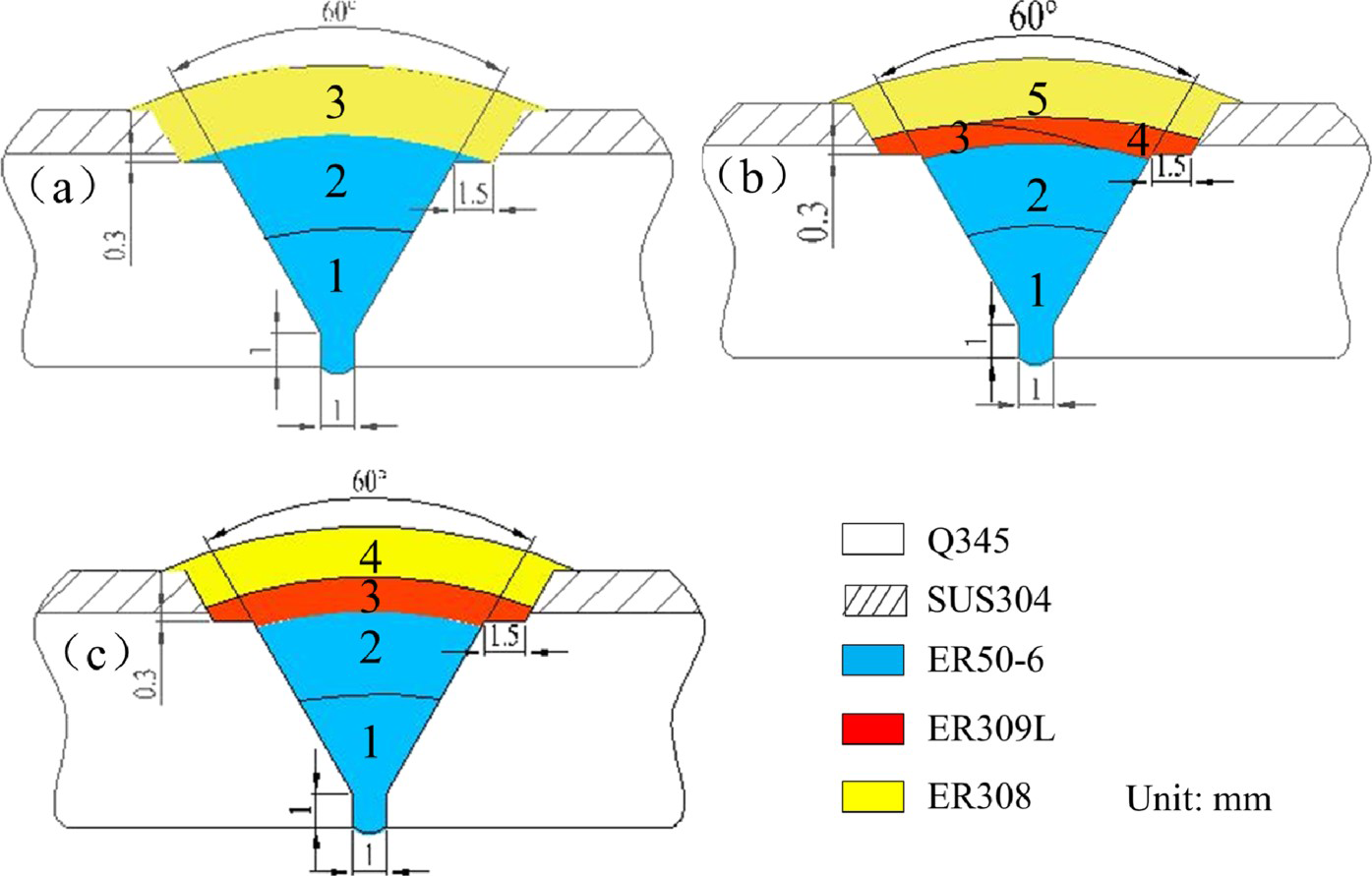
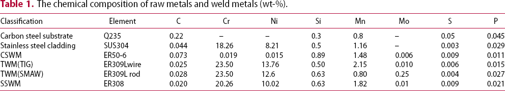
The chemical composition of raw metals and weld metals (wt-%).
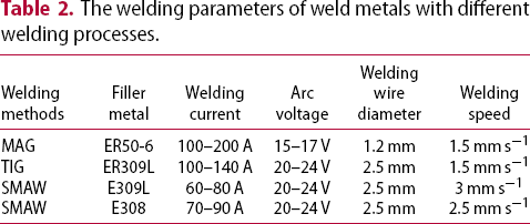
The welding parameters of weld metals with different welding processes.
The microstructure characterisation was observed and analysed by optical microscope (OM), ultra-depth three-dimensional microscope, scanning electron microscope (SEM) and transmission electron microscope (TEM). The penetrant inspections (PT) were carried out after welding to inspect the continuities and qualities of the entire welding joints. Vickers microhardness measurements were performed using a 100 g load for 15 s and a 100 mm spacing, the testing data were taken approximately at the centre of the weld cross-section (per sample). In addition, tensile testing was carried out on the bone-type tensile specimens with a gauge length of 75 mm and a width of 10 mm as illustrated in Figure 2(a), and the tensile tests were conducted with a crosshead speed of 2 mm min−1 at room temperature. The Charpy V-notch impact samples with a dimension of 7.2 × 10 × 55 mm were tested at different temperatures of −40°C, −20°C, 0°C and 25°C, and the specimens were carried out along three different notch directions, whose notches were located at SSWM (I1), CSWM (I2) and divider (I3) directions, respectively, as shown in Figure 2(b).
The schematic diagrams of testing specimens. (a) Tensile sample and (b) impact sample.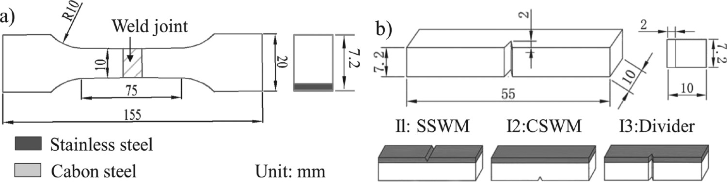
Results
Microstructure observation
Figures 3–5 show the optical microstructures of three welding joints in different areas of SSWM, CSWM, transition layer-weld metals (TLWMs) and the corresponding heat-affected zone (HAZ). All the welding zones and corresponding interfaces were well bonded, and the cracks, pores, unfused zone, incomplete weldment and slag inclusions were not found in the whole area, which are in agreement with the result of penetrant inspections (PT) of the entire welding joints. All the SSWMs contain austenite matrix and dendritic δ-ferrite phases, while the CSWMs mainly consist of grain-boundary ferrite (GBF), ferrite-side-plate (FSP) and acicular ferrite (AF). The -HAZ of NT sample contains GBFs and FSPs, while the HAZs of the other two welding joints are mainly composed of AF and nibble-like or equiaxed ferrites. The TLWM of the T-TIG sample consists of three zones: the central area is composed of intercellular ferrite formed at a faster cooling rate; the region near the SSWM consists of ferrite particles located at the three-point intersection and cells and the zone near the CSWM contains columnar ferrites along the solidification direction. However, the TLWM of the T-SMAW sample consists only of columnar ferrites as shown in Figure 5(b, C). The different TLWM microstructures of T-TIG and T-SMAW samples are attributed to the different chemical compositions, cooling rates and solidification modes of the two welding joints. It is worth noting that the SSWM bottom of the NT sample contains a certain amount of lath martensite (enlarged image of Figure 3(a)). It is because that welding the SSWM and CSWM of the NT sample directly causes the excessive diffusion of Cr and Ni elements from SSWM into CSWM [20]. However, the Cr and Ni contents at the SSWM bottom of T-TIG and T-SMAW samples are stable due to the protection of TLWM. Hence, there is no brittle martensite formed in the SSWM.
Optical microstructures of the whole welding joints without transition layers. (a) Interface between SSWM and CSWM and (b) interface between CSWM and HAZ. Optical microstructures of the whole welding joints of T-TIG sample. (a) Cross-sectional OM images; (b) interface between SSWM and TLWM; (c) TLWM; (d) interface between TLWM and CSWM and (e) interface between CSWM and HAZ. Optical microstructures of the whole welding joints of T-SAMW sample. (a) Cross-sectional OM images; (b) interface between SSWM and TLWM; (c) interface between TLWM and CSWM and (d) interface between CSWM and HAZ.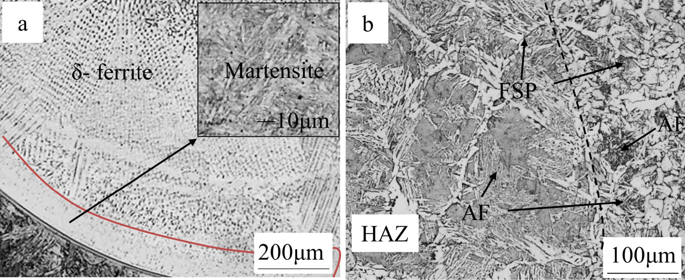
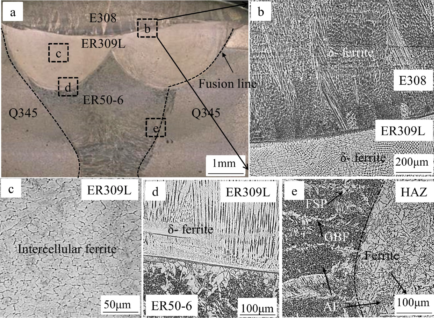
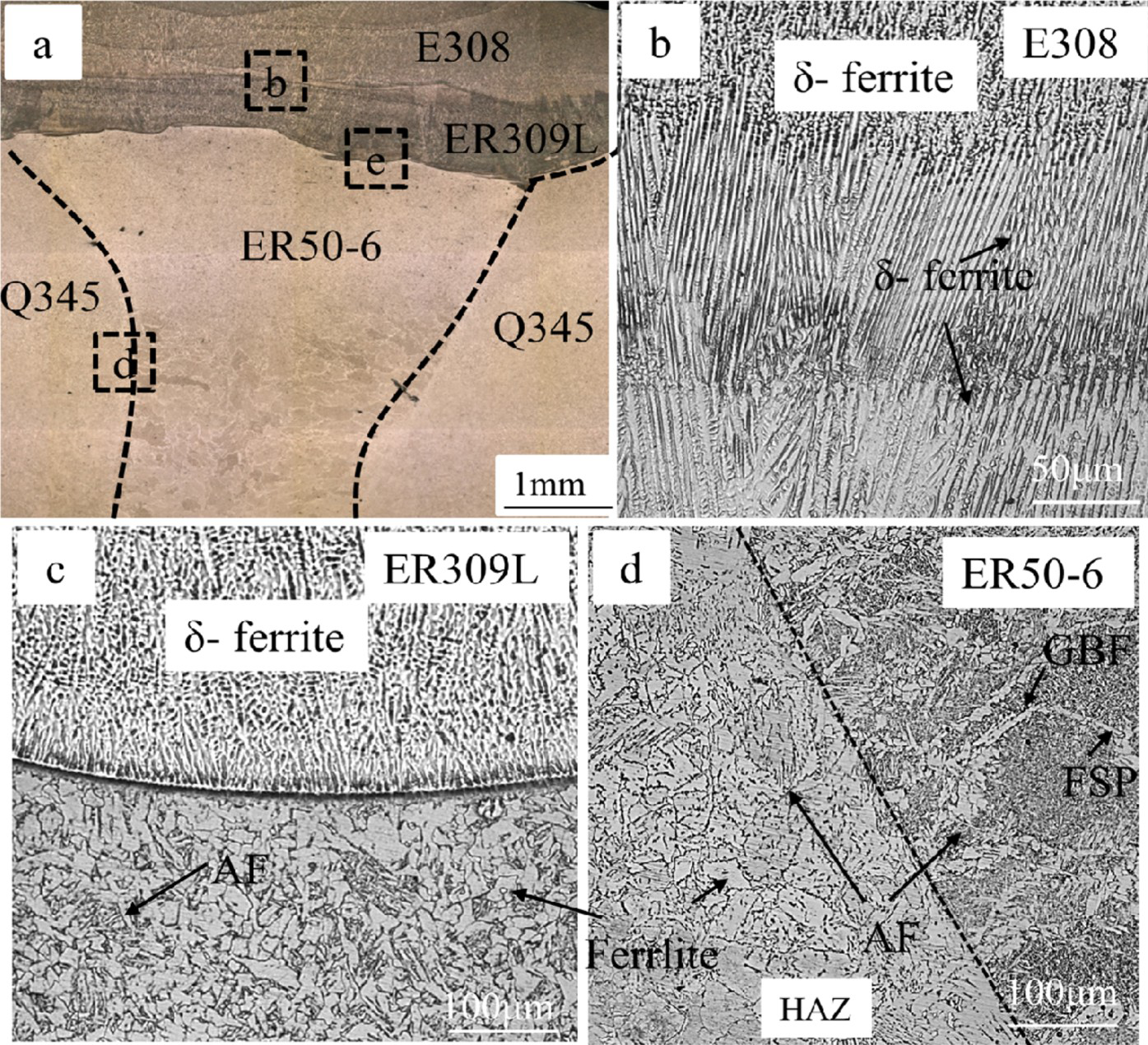
Figure 6 shows the EPMA mapping distribution of Cr, Ni elements for NT welding joints. The SSWM near the interface behaves a band-like element concentration distribution, which indicates a severe dilution behaviour of alloying elements during the welding process. The SSWMs of the T-TIG and T-SMAW welding joints are not excessively diluted by CSWMs due to the protection of transition layer, which is beneficial to the formation of enough δ-ferrite, thereby stabilising Cr element and improving the corrosion resistance [21].
The EPMA mapping distribution of Cr, Ni elements for NT welding joints.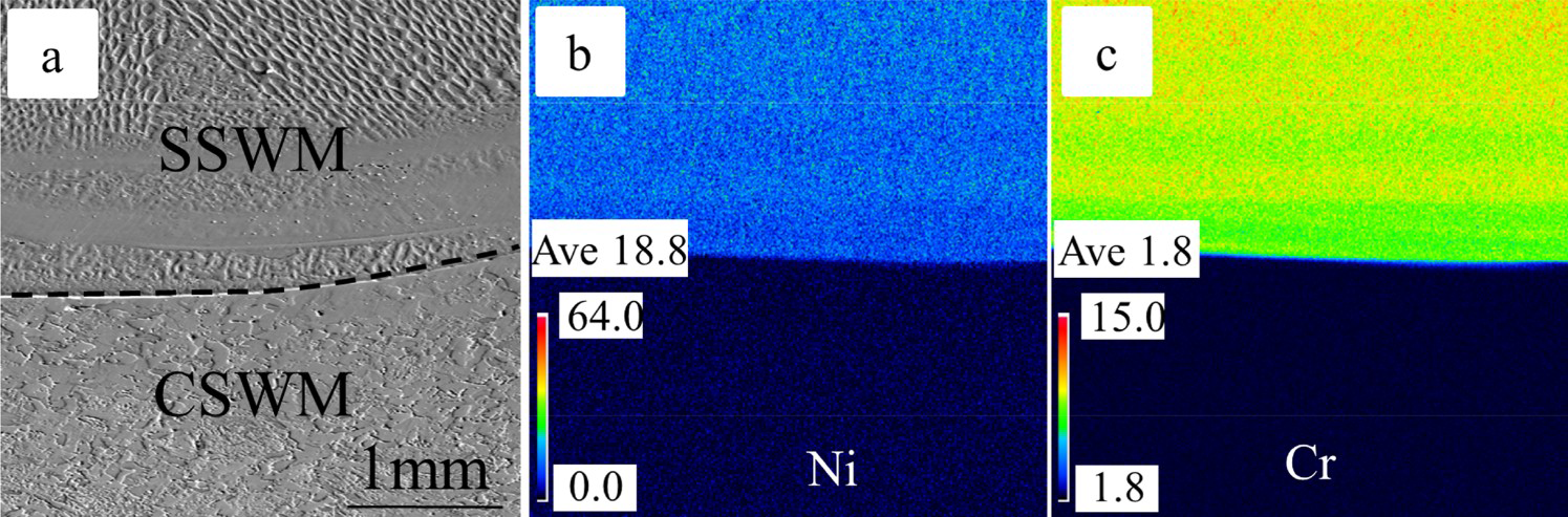
Mechanical properties
Figure 7 shows the microhardness distribution of three welding joints. For NT and T-TIG welding joints, the microhardness of both SSWM and CSWM away from the interface reaches approximately 250 HV. However, the hardness value of SSWM of NT welding joints near the interface reaches 524 HV, which may be attributed to the formation of martensite zone. The average TLWM hardness value of T-TIG welding joints is significantly higher than that of the SSWM. This may be attributed to that the high heat input causes a large amount of C element to diffuse from carbon steel substrate into TLWM, leading to the formation of hard Cr carbides [16], while the hardness value of the T-SMAW welding joint is basically maintained in the range from 210 to 240 Hv.
Microhardness distribution of three welding joints (a) NT; (b) T-TIG and (c) T-SMAW.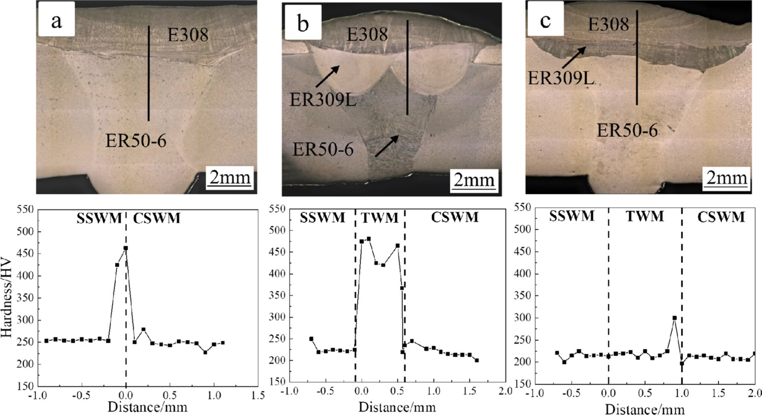
Figure 8(a) and Table 3 show the tensile properties of raw metals, stainless steel clad plate and stainless steel clad plate welding joints. These data indicate that the tensile strength and elongation of T-TIG and T-SMAW samples beyond that of raw carbon steel plate. The carbon steel plate and stainless steel clad plate have a yielding platform, which is not formed in other samples, and the same phenomenon appeared in Ref. [22]. In addition, the fracture positions of all the tensile specimens (as shown in Figure 8(b)) are located at the raw base clad plate rather than welding positions, which indicates that the welding joints achieved equivalent strength matching and good mechanical properties balance. Figure 8(c) shows the impact toughness vs. testing temperature relationship of T-SMAW samples notched along different directions, and the impact toughness of all the samples decreases with the decreasing testing temperature. At 25°C, the impact toughness of I1, I2 and I3 samples reached the maximum value of 190, 215 and 171 J cm−2, respectively. At the testing temperatures of 0°C and 25°C, the impact toughness of samples complies with the following order: I2 sample > I1sample > I3 sample. It is worth noting that at the testing temperatures ranging from 0°C to −40°C, impact toughness of all the samples decreases sharply with the decreasing temperature, and the fracture modes transform from ductile fracture to brittle fracture as shown in Figure 9, indicating that a significant ductile–brittle transition in this temperature range. Moreover, the impact toughness of the I2 sample decreases faster than the other two samples from 0°C to −20°C, indicating that the I2 sample has higher low-temperature sensitivity and ductile–brittle transition temperature to impact toughness.
The tensile and impact properties of samples. (a) Stress–strain curves, (b) macro pictures of tensile samples and (c) impact toughness vs. testing temperature curves of the T-SMAW sample along different notch directions. The impact fracture characteristics of T-SMAW welding joints along I3 direction at 25°C ((a–c) and −40°C (d–f)). (a), (d) The whole welding joints; (b), (e) SSWM and (c), (f) CSWM. The tensile properties of the raw carbon steel, raw stainless steel, stainless steel clad plate and stainless steel clad plate welding joints.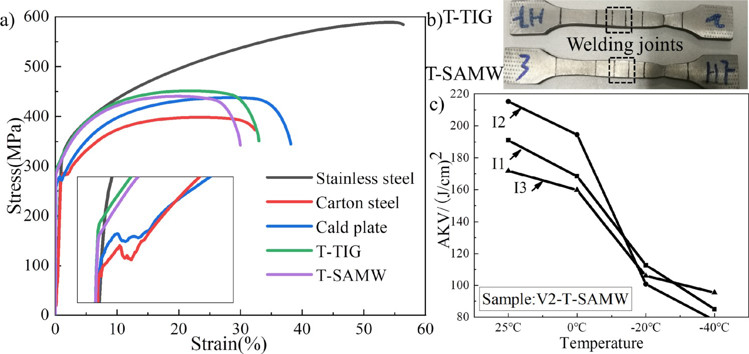
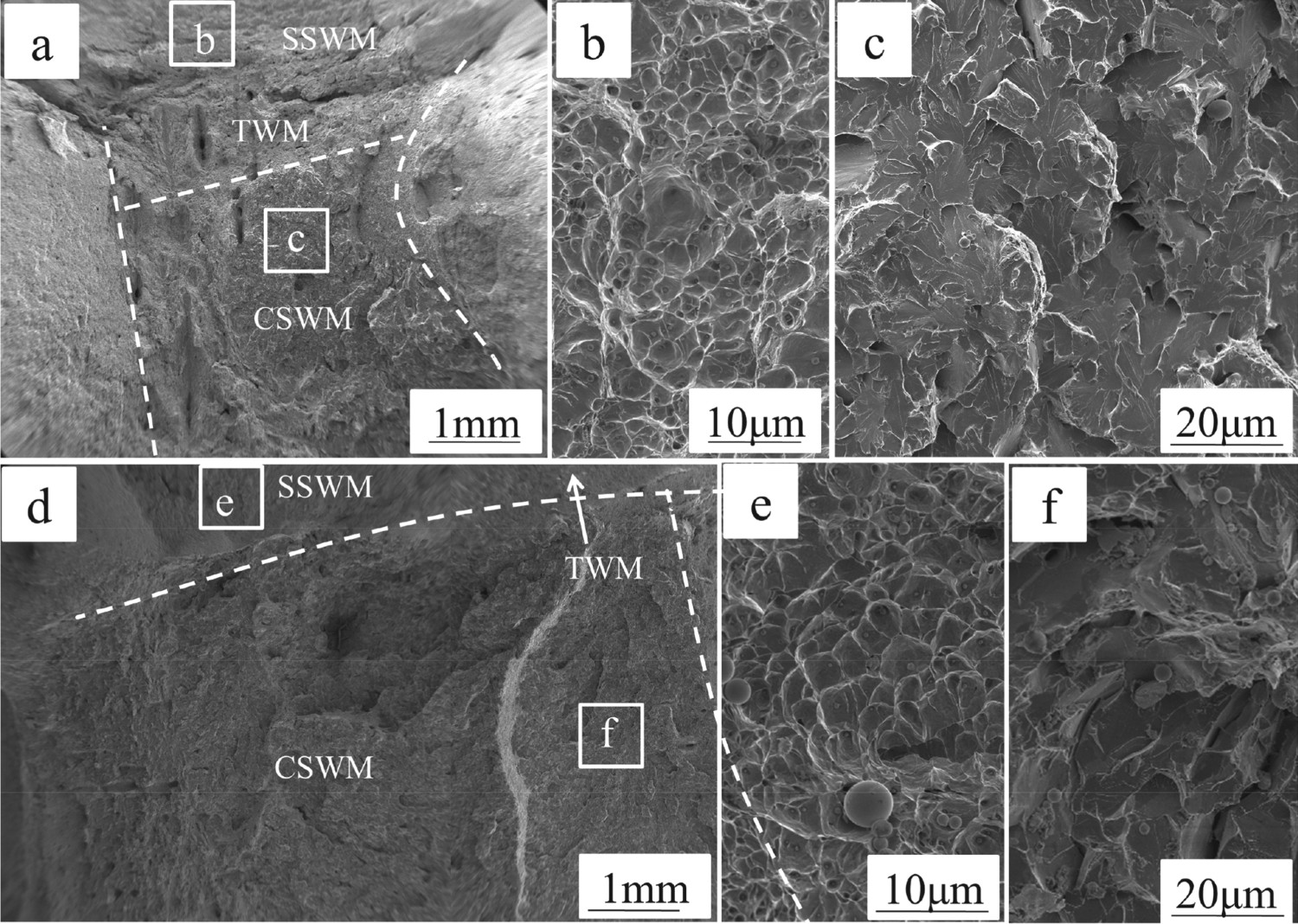
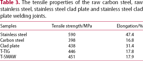
Figure 9 shows the impact fracture characteristics of T-SMAW welding joints along I3 direction at different temperatures of −40°C and 25°C, respectively. The obvious larger fibrous zone and shear lips are presented in the fracture surface of impact sample tested at 25°C. The fibrous zone represents a typical plastic fracture mode characterised by many fine and deep dimples. The impact fracture characteristic of the partial CSWM contains cleavage-like planes, small tearing ridges and microvoids, indicating a typical quasi-cleavage fracture mechanism. However, the fracture surface of the impact sample tested at −40°C appears larger flat plane, as well as smaller fibrous zone and shear lips. The dimples of SSWM become shallower and larger, and the CSWM zone presents a typical brittle fracture characterised by river-like cleavage fracture. Hence, the fracture mode transforms from ductile fracture and quasi-cleavage fracture to brittle cleavage fracture with the decrease of testing temperature.
Discussions
Figure 10 shows TEM microstructures of filler metals about welding joints. Herein, the SSWM microstructure near the interface (dotted line in Figure 3(a)) of NT sample consists of lath martensite with a width of 0.25 µm as shown in Figure 10(a). The formation of martensite is due to the excessive diffusion of alloy elements (such as Cr, Ni) from SSWM to CSWM. For the T-TIG sample, the central area of TLWM mainly contains intercellular ferrites with a width of 2.5 µm, which are uniformly distributed in the austenite matrix (as shown in Figure 4(c)). However, the intercellular ferrite is not formed in T-SMAW sample because of different chemical compositions, cooling rates and solidification modes.
The TEM microstructure of filler metals about NT welding joints. (a) Dotted line of SSWM, (b) EDS analysis in martensite, (c) TLWM microstructure of T-SMAW welding joints and (d) corresponding diffraction pattern of (c).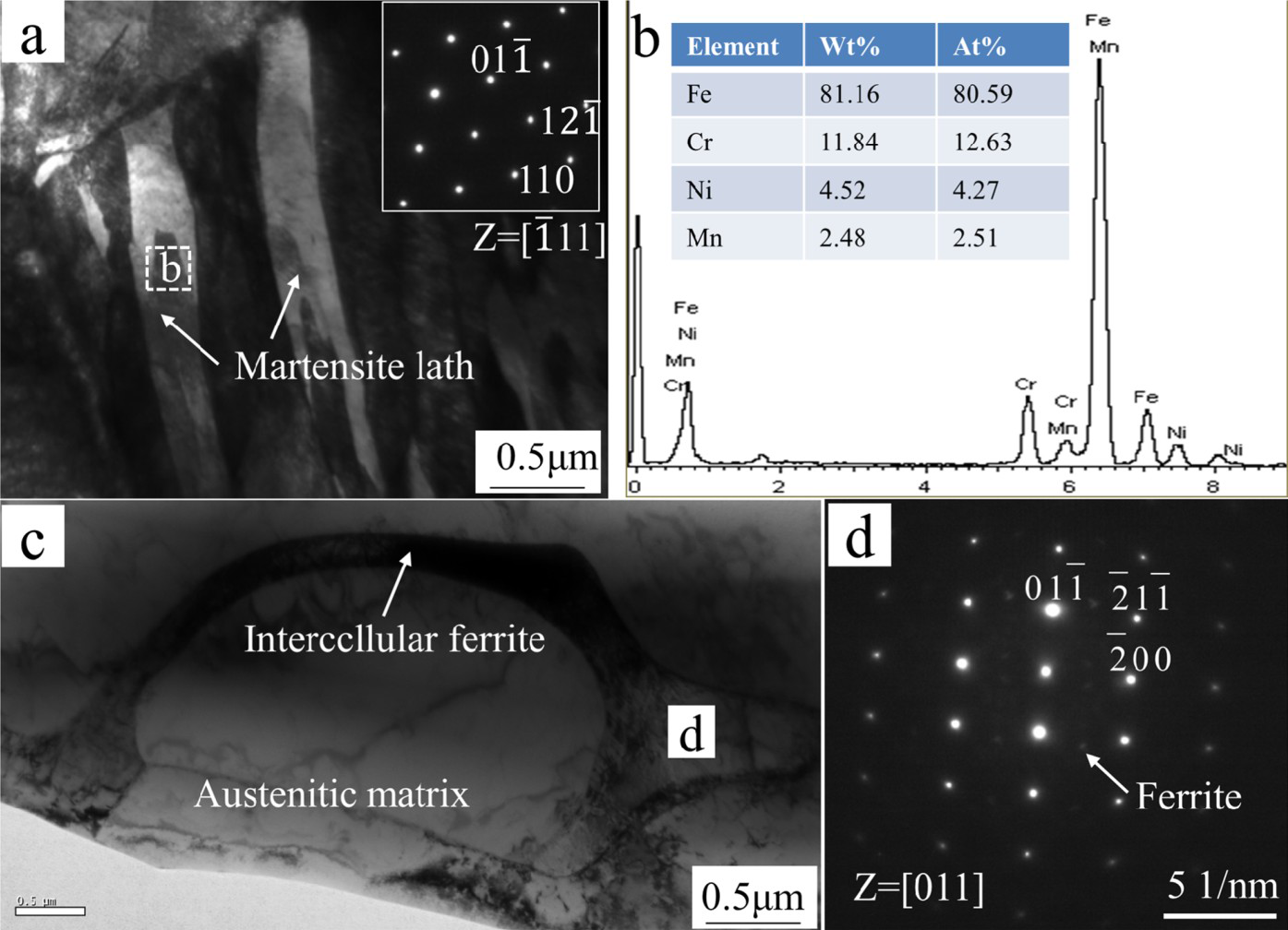
The different SSWM and TLWM microstructures of welding samples mainly depend on chromium equivalent/nickel equivalent (Creq/Nieq) value factors and cooling rate, and the corresponding Creq and Nieq of weld metals can be calculated using Schaeffler equations [23]:


The Cr, Ni equivalent value of weld metals of T-TIG and T-SMAW samples.
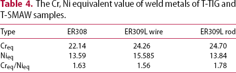
Figure 11 shows the cooling rate-chemical composition map and solidification microstructures with four principal modes [28, 29], and three solidification modes of weld metals were marked in the cooling rate-chemical composition map by squares. The room temperature microstructures of all the SSWMs were mainly developed from AF solidification mode, and the δ-ferrite was restricted to the cellular wall. Herein, the phase transformation sequence of alloying element depleted zone is as follows: L→L+γ→L+γ+δ→δ+γ. Moreover, the TLWM microstructure of the SMAW sample behaves in a FA solidification mode, which shows a typical cellular-like subgrain growing characterisation along the solidification direction. This solidification sequence is as follows: L→L+δ→L+γ+δ→δ+γ. In addition, the whole TLWM microstructure of the TIG sample follows the A + AF solidification modes → FA solidification mode → A solidification mode, and the solidified single-phase austenite corresponds to A mode as follows: L→L+γ→γ. The interface between SSWM and TLWM of the T-TIG sample consists of single austenite formed through A mode, and ferrite + austenite phase formed through AF mode. However, the interface between SSWM and TLWM of the SMAW sample consists of ferrite and austenite, which follows FA mode or AF mode. Therefore, the uniform microstructure transformation of the SMAW sample results in high impact toughness.
Cooling rate-chemical composition map [26, 29] and microstructures of the four principal solidification modes. (a) Cooling rate- chemical composition map; (b) interface between CSWM and TLWM(SMAW); (c) CSWM and TLWM(TIG); (d) CSWM; (e) interface between CSWM and TLWM(TIG); (f) TLWM(TIG) central area and (g) TLWM(TIG) area near SSWM.
Conclusions
The stainless steel/carbon steel clad plates were successfully welded by MAG arc welding, TIG arc welding and SMAW, respectively. The microstructure and mechanical properties of welding samples were investigated in detail. The main results are summarised as follows:
The microstructures of all SSWMs contain austenite matrix and dendritic δ-ferrite phases, corresponding to primary austenite with second-phase ferrite solidification mode. The microstructures of TLWMs welded by SMAW or TIG arc welding contain ferrite + austenite phase, but differ in the solidification mode. The former is only formed through primary ferrite with second-phase austenite mode, while the latter follows three solidification modes: single-phase austenite, primary austenite with second-phase ferrite and primary ferrite with second-phase austenite. The sample with the transition layer welded by SMAW has no obvious hardness gradient compared to other two samples. The SSWM without transition layer behaves excessive diffusion of Cr, Ni elements and the formation of brittle martensite zone, which can deteriorate corrosion resistance and mechanical properties of welding samples. The tensile strengths of clad plates with transition layer welded by TIG arc welding and SMAW, respectively, are both generally equivalent to that of raw stainless steel clad plate. The impact fracture mode transforms from ductile fracture to brittle cleavage fracture as the temperature decreases from −40°C to 25°C. The stainless steel clad plate welding joint with a high welding quality can be obtained by adding a transition layer using the SMAW method. The excessive alloy element dilution or brittle phase is absent in the SSWM. It has a perfect interface without an obvious hardness gradient, which is beneficial to high tensile properties and impact resistance.
Footnotes
Acknowledgements
This work is financially supported by the National Natural Science Foundation of China (NSFC) under grant number [51601055], the Natural Science Foundation of Hebei Province under grant number [E2018202245], the Joint Fund for Steel Research of National Natural Science Foundation of China and Baowu Steel Group Corporation Limited [U1860114], the Technology Innovation Strategy Funding Project of Hebei Science and Technology Department and Hebei University of Technology [20180106], the ‘One Belt and One Road'Technology Innovation Cooperation Project of Tianjin [18PTZWHZ00220], the Key Research and Development Program of Hebei Province, China [17391001D], the Foundation Strengthening Program [No:2019-JCJQ-142].
Disclosure statement
No potential conflict of interest was reported by the author(s).