
Abstract
Magnesium-lithium alloys are among the lightest commercially-available structural alloys. However, the reactive nature of Mg and Li makes fusion welding of this family of alloys very difficult, if not impossible. The solid-state joining processes are considered suitable alternatives since the joining can be carried out at temperatures well below the melting of these alloys. Refill Friction Stir Spot Welding (Refill FSSW) of 2.2 mm thick Mg-Li plates, using air and argon as the cooling gas, was investigated. Initial examinations revealed formation of adherent oxides-based residues on the tool shoulder. The microstructural examination of the air-cooled samples showed the presence of oxide inclusions within the weldment. As expected, the argon-cooled welding process reduced oxide formation and additionally resulted in flat and smooth welded surfaces. Nevertheless, and somehow unexpectedly, the presence of oxide inclusions in the air-cooled samples had no noticeable effect on the shear strength or microhardness of the joints.
Keywords
Introduction
Magnesium-lithium (Mg-Li) alloys have potentially broad applications in aerospace, aviation, transportation, electronic and defence industries due to their high strength-to-weight ratio, excellent anti-vibration performance and penetration resistance against high-velocity projectiles [1]. However, fusion welding of Mg-Li alloys results in very poor joints mostly due to cracking, decomposition, oxidation and grain coarsening. Therefore, low-temperature solid-state joining processes are regarded as suitable alternatives, to overcome the predicaments associated with fusion welding techniques [2].
Refill Friction Stir Spot Welding (Refill FSSW) is a relatively new solid-state joining process. The most significant advantage of Refill FSSW is that, unlike Friction Stir Spot Welding (FSSW), no keyhole is remained on the welded surface. The main stages of Refill FSSW process are illustrated in Ref. [3].
Microstructure and mechanical properties of the aluminium and magnesium alloys, spot welded by Refill FSSW, have been investigated in previous work. Li et al. [4] reported the presence of defects at or vicinity of thermal-mechanically affected zone (TMAZ), which proved to weaken the Refill FSSW joints. Xu et al. [5] concluded that the voids and incomplete refilling can be attributed to (1) insufficient flow of materials in the stir zone during refilling stage, (2) poor metallurgical bonding and/or (3) presence of residual stresses.
‘Hook’ is a common terminology used to refer to an upward bending of the original lap interface in Refill FSSW. Cao et al. [6] found that the ‘hook’ height correlated with the rotational speed, joining time and plunge depth, whereas the joint shear strength decreased with increasing the ‘hook’ height. Shen et al. [7] reported that defect-free welds could be fabricated using a modified tool with three grooves or notches on the shoulder.
Previous work also showed that the shear strength of Refill FSSW joints is severely sensitive to the heat input. Sajed & Bisadi [8] reported that a lower rotational speed resulted in a higher welding strength of Refill FSSW joints due to reduced slippage between the tool periphery and adjacent materials. Contri et al. [9] concluded that the ‘hook’ morphology and thermal input had a strong influence on the strength of Refill FSSW joints of AZ31 magnesium alloy. ‘Hook’ and voids are normally act as crack nucleation sites, and once a crack is formed, it propagates along the welded zone and results in final rupture of the joint. However, De Castro et al. [10] found that higher strength was correlated to larger stir zone area, which resulted from higher rotation speeds and deeper plunges of the welding tool. Shen et al. [11] found that the overlap shear strength increased with increasing the welding time and plunge depth.
To date, few reports were found on Refill FSSW of Mg-Li alloys despite their promising applications in various industries. A set of comparative experiments, using various different welding conditions, were performed to assess the influence of cooling gases (air and argon) on the microstructure and mechanical properties of the joints. The formation mechanism of the oxide inclusions and their effects on the mechanical properties of Refill FSSW joints were also studied. The novelty of this work is due to the facts that no prior reports were found on either Refill FSSW of this group of Magnesium Lithium Alloys or the use of argon and its effect on the joint strength.
Experimental procedure
Nominal chemical composition (wt. %) of LZ91 Mg–Li alloy used in this work.
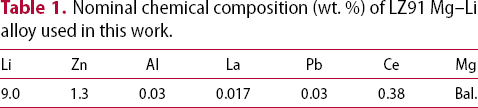
The welding tool had an 18 mm diameter clamping ring, 9 mm diameter shoulder and 5.2 mm diameter probe. In order to dissipate the frictional heat and avoid overheating of the welding tool, a cooling gas (compressed air or argon) was injected into the cooling channels of the welding tool during and after welding, as shown in Figure 1. The Refill FSSW joints were made using a standard Refill FSSW RPS 100 machine made by RIFTEC in Germany. All welding trials were carried out under a welding force of 15kN.
Built-in cooling system of Refill FSSW tool used in this work.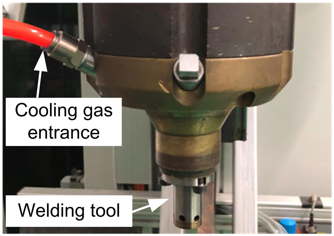
Before welding, alumina-based sandpapers were used to carefully polish the faying surfaces followed by rinsing in alcohol. The maximum time gap between the surface preparation and welding was 15 minutes. The dimensions of samples and test setup are shown in Figure 2 and welding parameters are given in Table 2. The welding time shown in Table 2 is the total time including all the stages of the welding process.
Specimen dimensions and welding setup used for preparation of lap shear test samples. Welding parameters of Refill FSSW experiments.
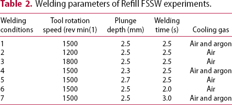
The lap shear tests were carried out using a universal tensile testing machine. The micro-hardness distribution across the weld spot was measured on Vickers scale under 200 g load for 20 s. Three specimens were prepared in each of the seven conditions shown in Table 2 (i.e. 21 samples in total) and all were shear tested. The average value of three shear tests was used when analysing the results.
The metallographic samples were ground and polished using conventional methods and etched in 5% nitric acid. Microstructural examinations of all samples were carried out using conventional optical microscope and FEI NOVA450 field emission scanning electron microscope (SEM) equipped with an EDS analyser.
Results and discussion
Defects and microstructures
A typical cross-section of the Mg-Li alloy Refill FSSW joints is shown in Figure 3. Based on the observed variations in the grain morphology and size, the weld zone can be classified into five distinctive regions: base material (BM), heat affected zone (HAZ), thermal-mechanically affected zone (TMAZ), shoulder affected zone (SAZ) and probe affected zone (PAZ).
Cross section of a typical Mg–Li alloy Refill FSSW joint consists of 5 distinctive regions.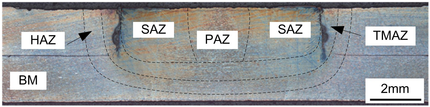
Figure 4(a) shows the grain morphology in the heat affected zone (HAZ), which are quite similar to those of the BM except less precipitates in the β phase due to high-temperature dissolution during the welding process. The elongated and textured grains in the thermal-mechanically affected zone (TMAZ) are the result of concurrent thermal cycle and moderate plastic deformation - see Figure 4(b). Figure 4(c) shows the shoulder affected zone (SAZ) which contains very fine and equiaxed α and β grains. This could be due to severe stirring of material and the dynamic recrystallization (DRX). The probe affected zone (PAZ) is located beneath the centre of the rotating probe and undergoes less materials movement and turbulence; resembling the clam zone in the eye of a hurricane. As can be seen in Figure 4(d) partial dynamic recrystallization (DRX) in PAZ resulted in a mixture of deformed and fine equiaxed grains.
Microstructures of the sample shown in Figure 4: (a) heat affected zone HAZ, (b) thermal-mechanically affected zone TMAZ, (c) shoulder affected zone SAZ and (d) probe affected zone PAZ.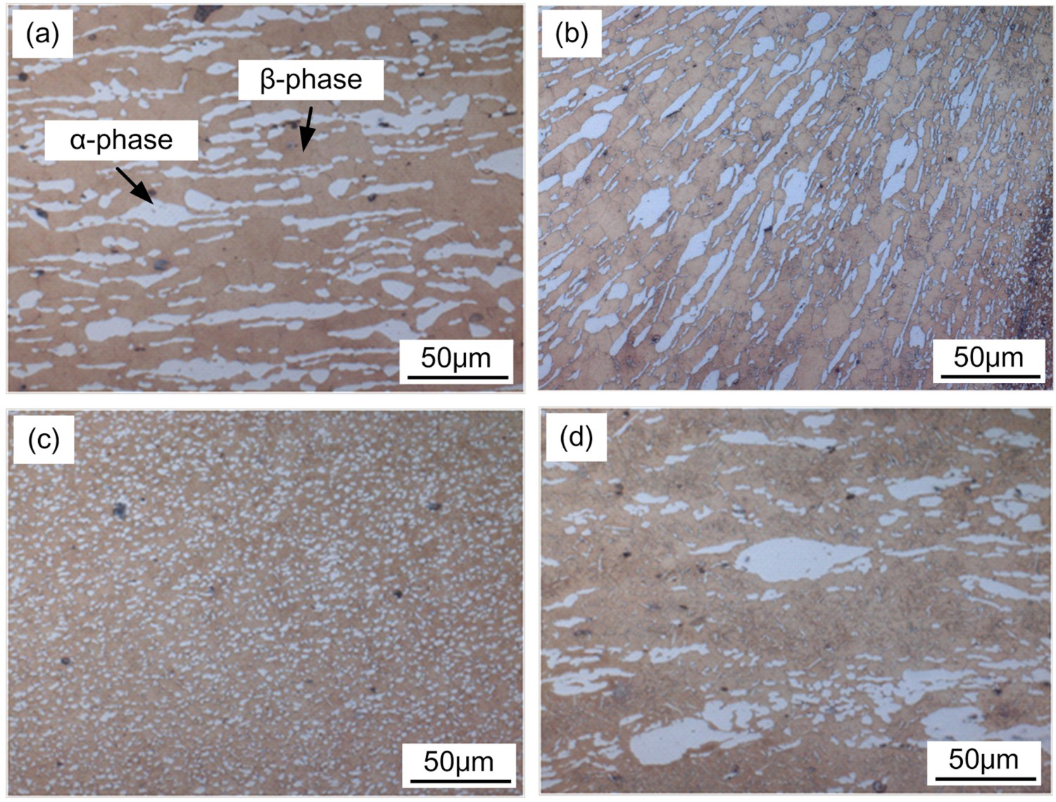
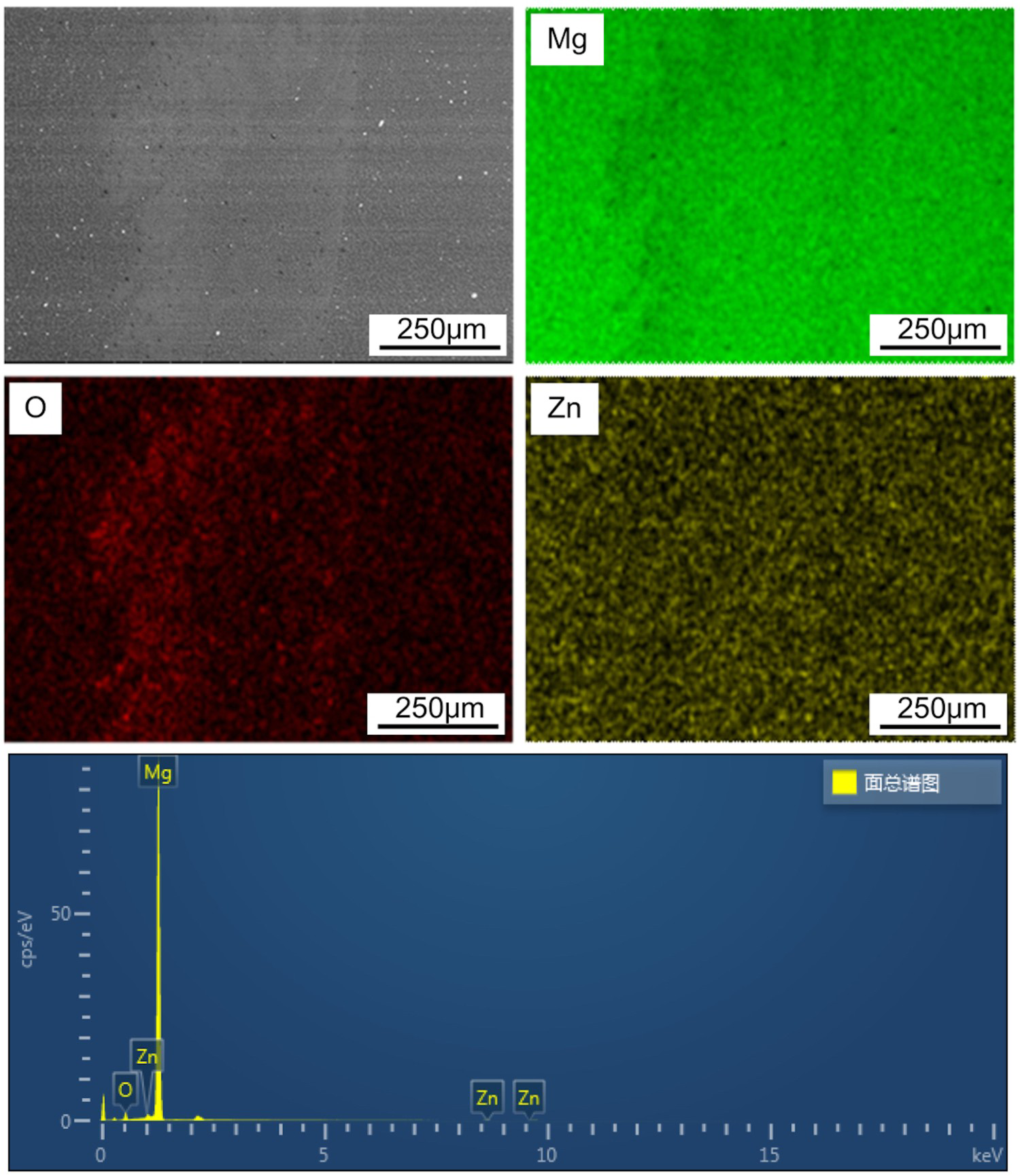
Figure 5 shows common types of defects found in the samples made in this work. The corresponding back-scatter SEM micrographs and elemental mapping (Figure 6) indicated that the dark zones, seen in Figure 5(a), are mainly oxide inclusions. This was confirmed by the EDS analysis which shows the presence of about 4.6 wt.% oxygen in dark zones. It should be noted that Li element cannot be detected by EDS due to its light atomic weight. These inclusions were abundant around the TMAZ and SAZ boundary regardless of the welding conditions used. The strong affinity of Mg and Li to oxygen is the main cause of the formation of oxide-based inclusions. The formation mechanism of the oxide inclusion is discussed in the following Section 3.2. A ‘hook’ with about 0.3 mm height was only found in the joint with a plunge depth of 2.7 mm (see Figure 5(b)), which is attributed to the excessive material flow during the refill stage. Partial bonding was observed in all the specimens (see Figure 5(c)). Contri et al. [9] has stated that the partially bonded zones and ligaments contain large amounts of the oxide film remained from the initial faying surfaces. Interestingly, such continuous defects were mostly found in the joints made using a low rotational speed of 1200 RPM, probably due to insufficient heat and material flow.
Defects observed in Mg–Li alloy joined by Refill FSSW; (a) oxide inclusion (b) ‘hook’ and (c) partially bonded zone and ligaments containing oxides and voids. Back scatter SEM micrograph, elemental maps and EDS analysis indicate high concentrations of oxygen (4.6 wt-%) and magnesium (94.2 wt-%) in the TMAZ and SAZ interface of sample shown in Figure 5(a).
Effect of using different cooling gas on formation of oxide inclusions
The chemically active nature of Mg and Li makes the alloy prone to oxidization during Refill FSSW process. In order to investigate the oxidisation mechanism, a new Refill FSSW tool, was used in the work (shown in Figure 1).
The first welded spot, when using an air-cooled ‘clean’ tool, contained a limited amount of oxide at the TMAZ and SAZ interface. However, more and more inclusions were found in the subsequent welding attempts using the same tool already covered with the debris left from previous welding attempts. Figure 7 shows build-up of very adherent oxide residues on the welding tool. Close examinations suggested that most of oxidation occurred when the tool is detached from the first spot, allowing the heated probe and shoulder to be exposed to ambient oxygen. During the subsequent welding cycles the oxide-contaminated welding tool plunges into the plates and injects oxides into the weldment. Therefore, in order to minimise oxide inclusions within the joint interface, the Refill FSSW tool must ideally be kept free of any debris. However, it is not feasible to clean the welding tool after every and each spot-welding cycle. A practical solution proved to be the use of argon instead of air as the cooling gas, which resulted in formation of far less oxide residues on the tool. It would be of interest to try nitrogen which is a much cheaper gas than argon.
Use of argon as the cooling gas prevented the formation of excessive debris and oxides on the welding tool.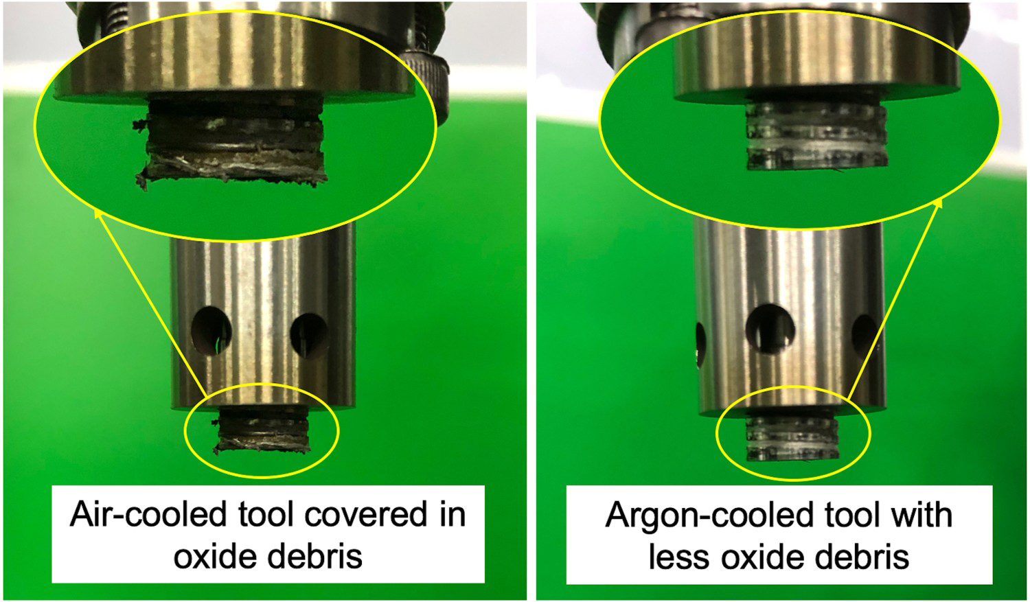
As shown in Figure 7, far less oxide inclusions and debris were stuck on the argon-cooled welding tool. This led to more effective sealing between the rotating shoulder and plasticised materials and hence less exposure to ambient oxygen in the subsequent welds. In short, the less the debris stuck on the welding tool the less the oxidation in the following weldment.
The surface morphologies of the welded spots produced using air and argon, as the cooling gas, are shown in Figure 8. The welded spots with air cooling exhibited rough features with black spots containing oxides on the surface, whereas the argon cooling improved the smoothness of the weldment considerably.
Surface morphologies of the welds made under three welding conditions (rotational speed/plunge depth/time) and using two different cooling gases.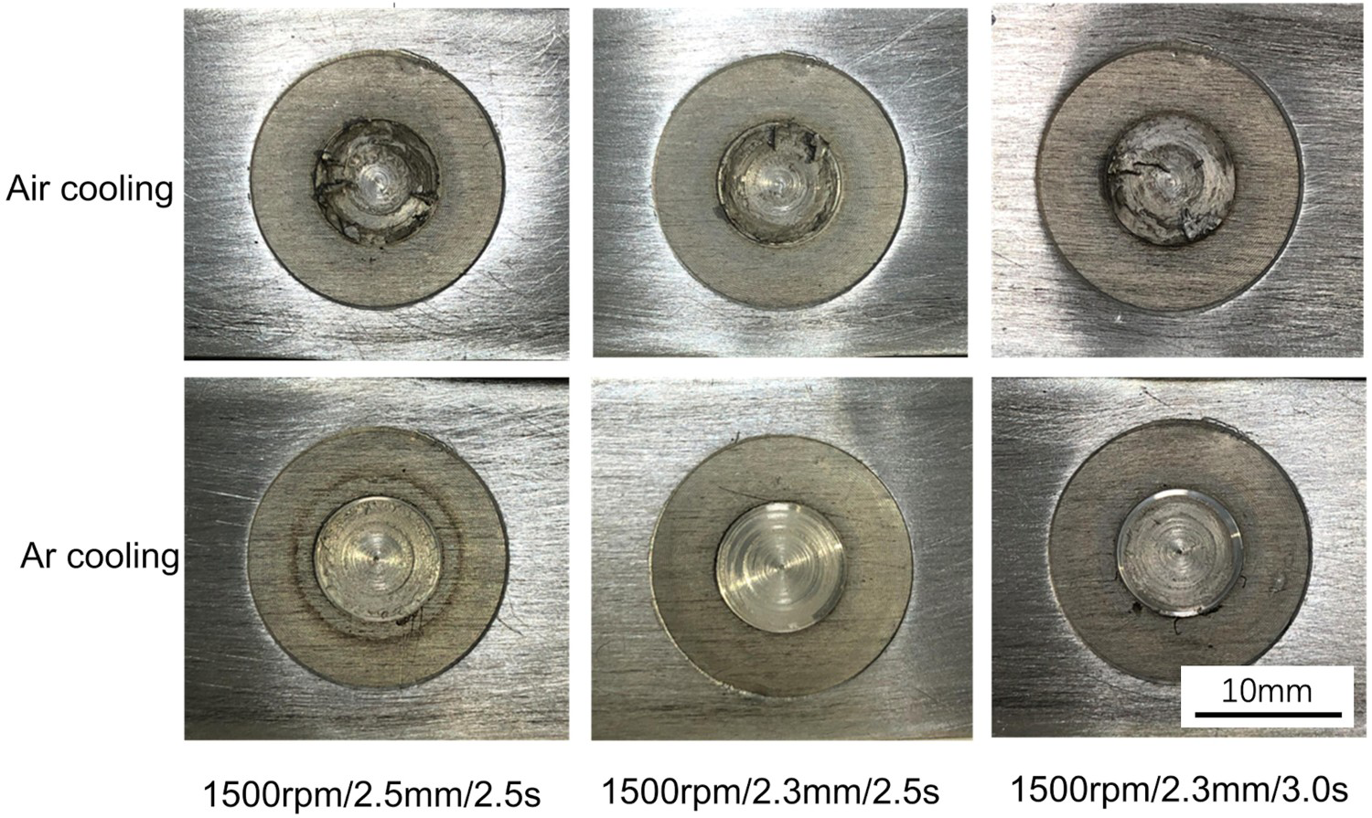
The microstructures around the TMAZ and SAZ interface in the joints obtained using air and argon-cooled tools are shown in Figure 9. The microstructural analysis show there is a substantial reduction in the oxide content around the TMAZ and SAZ interface when using argon instead of air. Therefore, it was concluded that the use of argon improves both surface smoothness and joint microstructure.
Microstructures of TMAZ and SAZ interface of the samples shown in Figure 8; use of argon resulted in less oxidation throughout the weldments.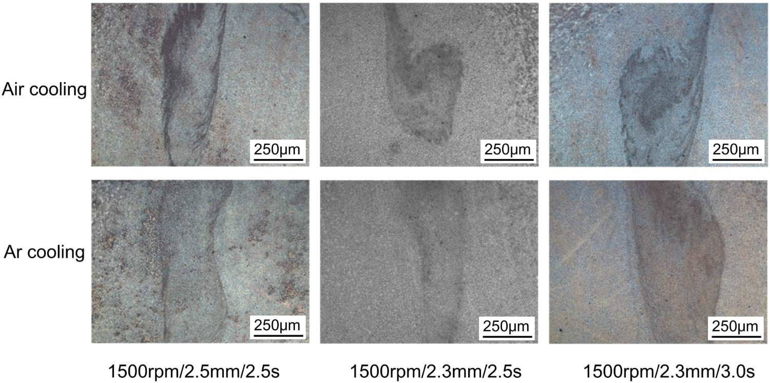
Mechanical properties and fracture modes
The results of shear tests carried out on the joints made using various conditions and air or argon are shown in Figure 10. Quite unexpectedly, the variation in the shear strengths is rather small and within the experimental error. Therefore, it can be concluded that the welding conditions used in this work and the type of cooling gas had no noticeable effect on the shear strength of the Refill FSSW joints.
Shear strength of the joints made under various welding conditions (rotational speed/plunge depth/time) and using different cooling gases.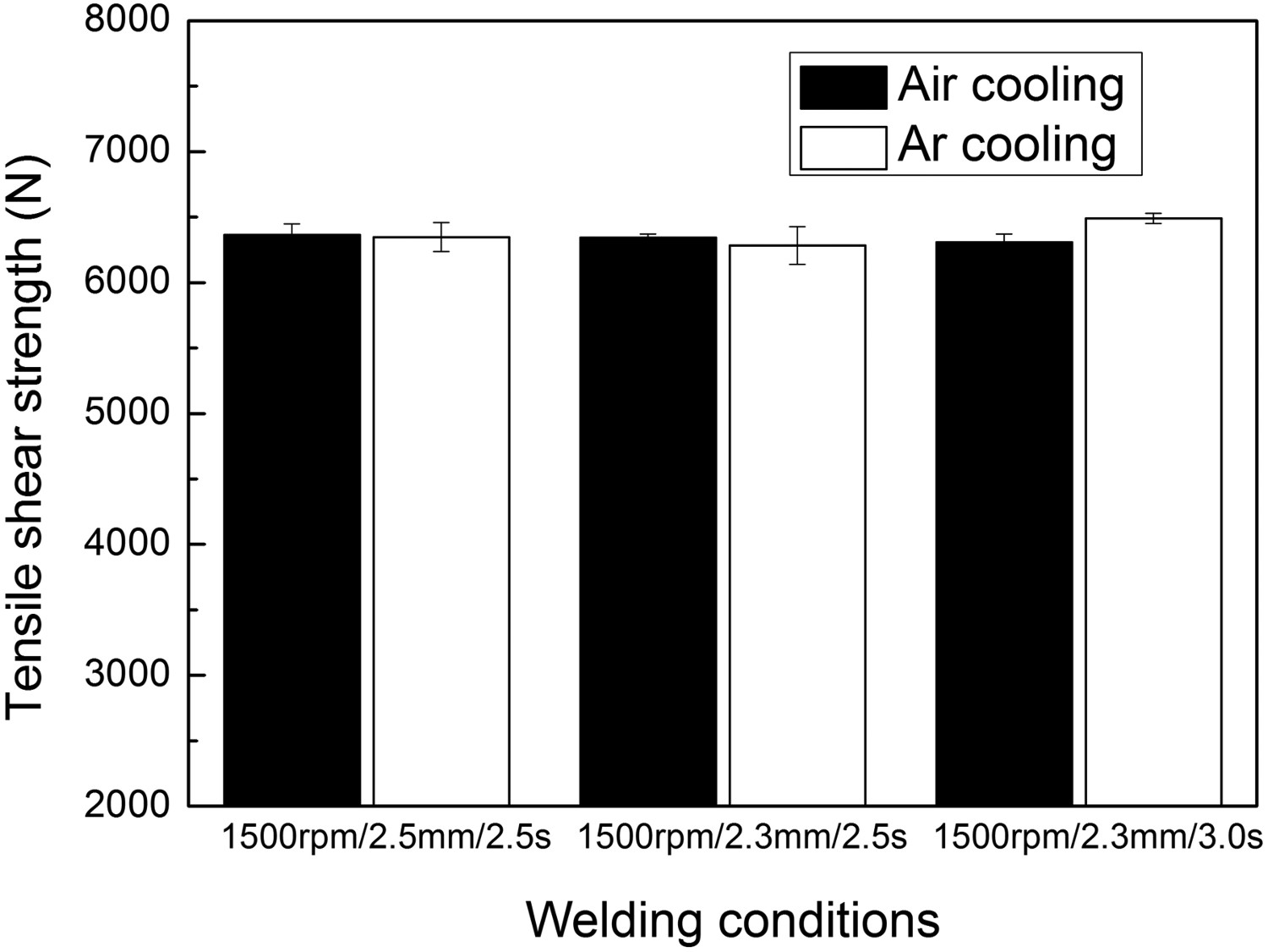
Two types of fracture mode were found in the shear tested samples. Type I fracture, seen in Figure 11, is a cohesive failure which occurred in the HAZ of the upper plate with no effect on the lower plate. Type II fracture is also a cohesive fracture, but the rupture occurred in the HAZ of both upper and lower plates. Clearly, in both fracture types, the crack nucleated around the tip of the ‘hook’ or partially bonding area before propagating into the HAZ. Therefore, the areas around ‘hook’ and partially bonded zone are considered as the weakest points, despite the presence of oxide inclusion around the TMAZ and SAZ interface. It should be noted that type I fracture was only found in the samples made using Condition 7 (see Table 2), in which a longer welding time resulted in higher shear strength. Also, it is worth mentioning that the fracture mode was the same for air and argon cooled samples provided the same welding conditions were used. Since none of the tested samples was fractured in its joint interface, it was not possible to conduct a comparative fractography on any of the welded samples.
Fracture modes of shear tested Refill FSSW samples. Type I fracture always occurred in upper plates whereas both upper and lower plates failed in Type II fracture.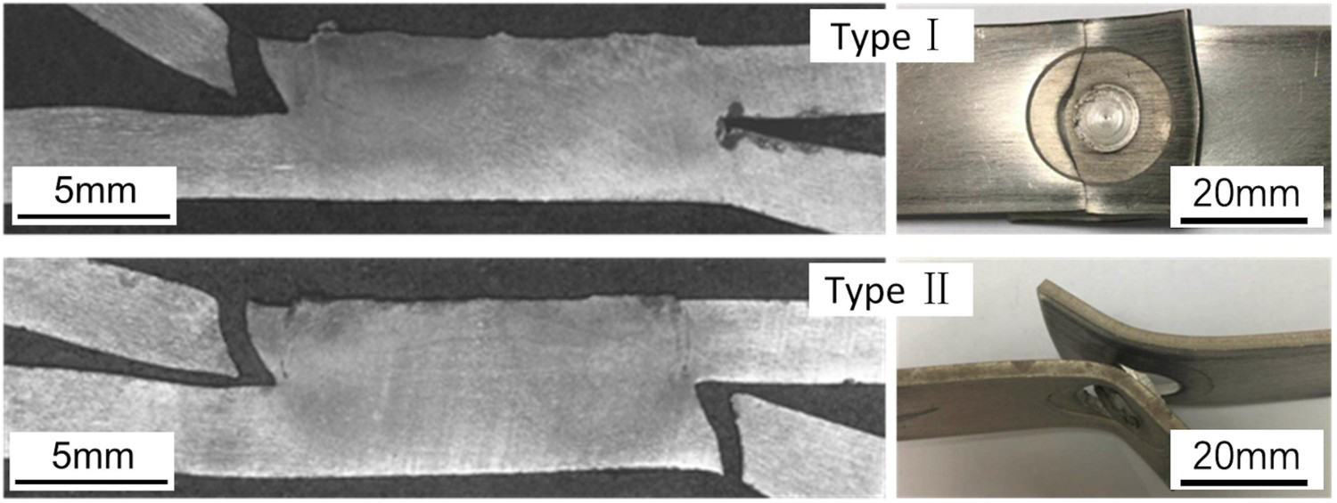
Figure 12 shows small variations in the microhardness across the Refill FSSW joints of Mg-Li alloy with hardly any benefit from using argon rather than air as the cooling gas. The results of microhardness tests shown in Figure 12 are in good agreement with the result of shear tests seen in Figure 10. The hardness of the welded zone is slightly higher than that of Base Materials (BM), probably because of the grain refinement of the welded zone due to dynamic recrystallization.
Microhardness in the Refill FSSW joints of Mg–Li alloy made using different cooling gases.
Conclusions
The effects of using air and argon, as a cooling gas, on the microstructure, shear strength and microhardness of the Refill FSSW joints in Mg-Li plates were investigated. Based on the experimental results the following conclusions were confidently made.
Oxide inclusions were found in the refill-friction-stir-spot-welded Mg-Li plates due to the high affinity of Mg and Li to oxygen. Use of argon as a cooling gas resulted in the formation of flat and smooth surfaces as well as reduction in oxide inclusions in the joint area. Unexpectedly, the high content of oxide inclusions, when using an air-cooled tool, had no major effect on the shear strength or microhardness of the welded Mg-Li plates.
Footnotes
Acknowledgements
The authors would like to acknowledge the technical assistance, helpful discussion and advice received from Mr Zhijun Li, Mr Chunsheng Sha and Mr Songbin Li.
Disclosure statement
No potential conflict of interest was reported by the authors.