
Abstract
In this study, copper/steel composite tubes were produced by an underwater explosive welding process. Scanning electron microscopy, energy dispersive spectroscopy, electron backscatter diffraction and hardness tests were performed to analyse the microstructure and properties of the composite tubes. It was shown that by using an aqueous medium as a constraint, the inner tube cladding surface could be protected, shape distortion was reduced and the stringent requirements on the outer steel die were reduced. The results show that the copper/steel bond interface has a high-strength fine grain layer and that work hardening occurs near the interface after tube lamination.
Keywords
Introduction
In recent years, composite pipes have developed rapidly in the fields of petroleum, aviation, military and nuclear industries [1, 2]. With the massive consumption of petroleum resources and the consumption of large conventional oil and gas fields, oil and gas fields are developing towards harsh environmental conditions. Conventional energy is being replaced by nuclear energy, and these environments are usually accompanied by high corrosiveness [3-5]. In addition, the use of nuclear energy has made long-term nuclear waste management an important research topic [6, 7]. One current solution for nuclear waste is to bury spent nuclear fuel in deep underground storage [8]. The reactor fuel bundles are packaged in used fuel containers and the copper/carbon steel composite structure is made into a structural containment and then placed in underground rock formations [8, 9]. A few millimetres of copper layer can keep the fuel container intact for 1 million years.
Many coating technologies based on cold spraying and thermal spraying usually do not provide adequate corrosion and wear protection, and it is difficult to produce coatings on the inner surface of long pipes [10, 11]. Many metal materials with excellent corrosion resistance are used, but they are not suitable for mass use due to the high cost [12]. Studies demonstrated that the use of composite pipes is the effective way, which is relatively safe, economical, reliable, and solves a reasonable match between corrosion resistance and strength under severe corrosion conditions [13-16].
Composite pipes are made of a combination of a high-strength inexpensive material in the outer layer and a relatively thin corrosion-resistant material in the inner layer, whose cost can be significantly reduced relative to the use of a single expensive material [17]. Composite tubes are divided into mechanically compacted tubes and metallurgical composite tubes [18, 19]. Mechanically bonded is less expensive and has a wider range of applications, but has lower strength relative to metallurgical bonding and the mechanically bonded seam is a weak site for corrosion [20]. Owing to the large difference in physical properties between the base tube and the inner tube, some coatings prepared by many coating technologies have poor adhesion to the steel substrate, and problems such as cracking and low corrosion resistance are prone to occur after welding [21, 22]. Moreover, the conventional explosive welding process is easy to cause serious distortion or even fracture of the composite pipe [23].
Therefore, this paper proposed an underwater pipe explosive welding process, which is based on the experience of existing underwater plate explosion welding to improve the process. In this process, water as a pressure transfer medium makes the explosion act on the metal tube shock wave more uniform, while its advantages include no ablation of the metal due to the heat of the explosion, water restrains the distortion of the composite tube, high welding strength of the interface and low cost of tube underwater explosive welding. In addition, weld joint in explosive welding is created in solid-state with high strain rate collision and plastic deformation along the overlapping metallic materials interface. In this paper, an internal underwater explosive welding process was used to successfully prepare a Cu/Fe composite tube with a metallic luster and non-destructive surface. Then, the organisation and mechanical properties of the explosion welded interface were studied using scanning electron microscopy (SEM), energy dispersive spectroscopy (EDS), electron backscatter diffraction (EBSD) and microhardness.
Materials and method
In this study, copper and mild steel composite tubes were fabricated by an underwater explosive welding process. In order to promote this fabrication method in the field of explosive welding, mass-produced tubes with standard diameters and thicknesses were chosen here as raw materials (without additional machining and without unnecessary material losses). As shown in Figure 1, the copper tube was used as the inner tube with an outer diameter of 60 mm and a wall thickness of 2 mm, while the mild steel tube was used as the outer tube with an outer diameter of 85 mm and a wall thickness of 10 mm. The copper tube and the steel tube were placed concentrically with a fixed gap of 2.5 mm between them. In addition, a steel mold with an inner diameter of about 88 mm and a wall thickness of about 10 mm is placed in the outermostlayer.
Layout of the underwater explosive welding configuration and schematic diagram.
Components of the emulsion explosive used in Cu/Fe tube explosive welding.
EDS point scan results (at.-%) and corresponding test areas marked in Figure 5.
Then, the inner and outer tubes are placed concentrically by keeping a gap of 2.5 mm, the bottom is sealed with glue, and then 25 wt-% HGMs mixed with emulsified matrix are put into the paper tube and placed in the centre of the inner tube to obtain the final structure of the explosive welding configuration. Finally, the device is detonated before being placed in water.
In order to understand the microstructure and mechanical properties, samples with different welding conditions were evaluated. According to Figure 1, in order to fabricate copper/steel clad tubes, the surfaces were cleaned with alcohol after grinding the received material. The samples were observed with SEM (JSM-7800F) equipped with an EDS according to standard metallographic procedures, sanded and polished at different locations parallel to the burst direction (RD). The variation of hardness with distance from the interface is given in a Vickers hardness test with an applied load of 200 g. The EBSD samples were prepared by grinding and polishing followed by polishing with a precision ion milling (IB-19530CP). The interface was then tested for EBSD (Nordly max 3).
Results and discussion
Macromorphology
The results of the copper–steel composite tube fabricated by the underwater explosive welding process and its contours are shown in Figure 3, which examines the changes in the shape and dimensions of the tube after the explosion welding (Figure 2). During explosive welding, the inner copper tube is accelerated outward towards the outer steel tube, and collision takes place [25]. As shown in Figure 2, the outer diameter of the outer tube and steel mold tube after the explosive welding is larger than the original size. In addition, the sparse wave effect on both ends of the tube is relatively small explosive energy, thus the deformation is relatively small [26]. Notably, the inner diameter of the steel die size used in the test was larger than the inner diameter of the outer tube, and the outer tube was not tightly bound to the steel die. However, the composite tube remained intact after the explosive welding and did not fracture due to the tensile stress during the increase of the outer diameter (Figure 3). In addition, the outer diameter of the composite tube after explosive welding was even lower than the original size of the inner diameter of the steel die, which allowed the Cu/Fe composite tube to be removed directly from the integral steel die after explosive welding. This may be attributed to the incompressibility of the water between the outer tube and the die, which allows the water that is squeezed during the explosive welding to act as a restraint on the deformation of the composite tube [27].
Dimensions of components before and afterexplosive welding. Welding results of Steel/Cu composite tube.
As shown in Figure 3, the inner surface of the Cu/Fe composite tube has a smooth surface and still possesses a metallic luster after the explosion welding. This indicates that the use of water is also beneficial to protect the surface of the composite tube from ablation by explosives, which facilitates the manufacture of high surface quality composites reducing the cost of secondary processing [28, 29]. Therefore, the shape and surface of the composite tube after welding changes indicate that the underwater environment is conducive to improving the quality of the explosive welded tube.
Microstructures at different locations
The interface morphology was observed along the explosion welding direction (longitudinal section), and the SEM images of the bonding interface of the Cu/Fe composite tube are given in Figure 4. As shown in Figure 4(a,c,e), the front and middle interfaces have no obvious waveforms close to flat. After magnified observation as in Figure 4(b,d,f), the bonding interface of Cu/Fe bond has continuous small waves below 20 μm, and the wave amplitude and wavelength change significantly at different parts: at the front part, the wavelength is from about 42 μm and the wave amplitude is about 10 μm (shown by red dashed lines). In contrast, the wave period at the Cu/Fe interface observed from the middle part is about 48 μm and the amplitude is about 13 μm, and the waves are more irregular, even with a melting band transition layer at the Cu/Fe interface. However, this irregular wavy interface with melting bands gradually changes to a small wavy interface with a wavelength of about 30 μm and an amplitude of about 10 μm in the rear part of the sample, and the size and morphology are similar to those in the front part.
BSE images and enlarged view of Cu/Fe welded interface from (a,d) the front-end part; (b,e) the middle part; (c,f) the back-end part.
Microhardness distribution
Microhardness measurements were performed on cross sections through Cu/Fe specimens so that the change in hardness from the outer surface of the copper to the Fe substrate at different locations could be determined. These results show that the microhardness of the different sections does not differ significantly after the explosion welding (Figure 5(a)). The highest hardness of the two joining alloys appears directly after the explosion near the Cu/Fe composite interface. From Figure 5(b), it is evident that the highest values of microhardness were obtained near the bonding interface, for copper of about 143 HV and for Q235 steel of about 230 HV. The high microhardness values close to the bonding interface indicate a large plastic deformation of both alloys in this region [17, 30]. The hardness values fluctuate more in the steel side of the composite tube after underwater explosive welding, while the hardness data on the copper side fluctuate less (Figure 5(b)). All three locations have similar hardness, so in this case, the explosive welding does not cause significant differences in the performance of different parts of the joint.
Hardness distribution: (a) different position; (b) statistics.
Microstructure evolution
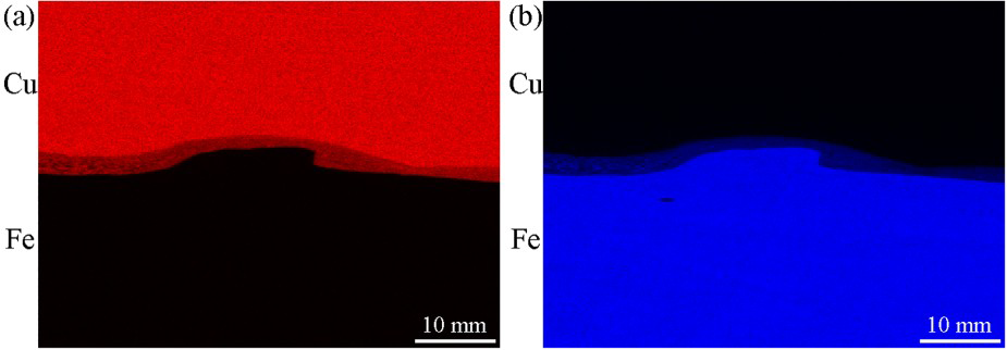
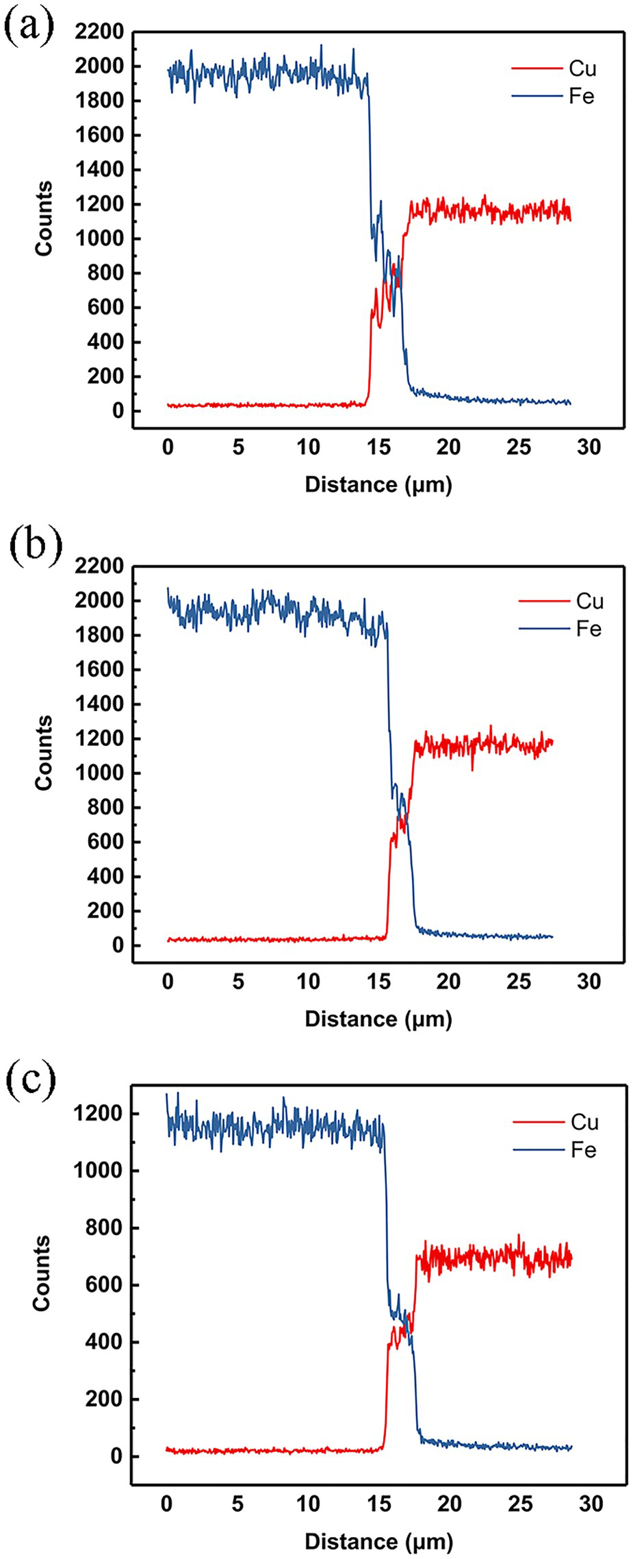
In order to study the microstructure of the interface of underwater explosion welded copper/steel composite tubes, EBSD observation and EDS analysis were performed. The test positions are shown in Figure 6 and the corresponding results are shown in Figures 7–9. The element mapping given in Figure 7 shows the transition layer region with thickness of 1–2 μm at the copper/steel interface and distribution along the interface. Figure 9 shows the inverse pole figure (IPF), recrystallisation distribution figure and kernel average misorientation figure (KAM) near the interface, respectively, where the overlapping areas of Cu and Fe element distribution in Figure 7 are strong evidence of the chemical composition change between the parent material and the transition layer. In order to reveal the trend of chemical element changes, EDS line scans were performed at the test positions L1, L2 and L3 marked in Figure 6. It can be seen from Figure 8 that different locations show different element distribution characteristics, which well reflects the element distribution characteristics of the transition layer, with relatively slow element changes in the middle of the transition layer, while near the matrix is the element content will change sharply. The point scan in Figure 6 shows a single element of the matrix on both sides of the transition layer, while the transition layer has nearly equal proportions of Cu and Fe elements (Table 2). The appearance of the transition layer can be explained by the explosive welding interface formation mechanism, in which the elemental demarcation evident on both sides of the transition layer is mainly the result of the metal strongly bonded to the base under extreme temperature and pressure conditions, while the interior of the transition zone is the result of atomic diffusion after experiencing strong melting [10, 31].
EBSD test area and EDS test location Element mapping: (a) Cu; (b) Fe. Line scan results span the transition layer in Figure 5: (a) L1; (b) L2; (c) L3. The designated area observed by EBSD: (a) IPF,(b) recrystallisation distribution figure (c) KAM.
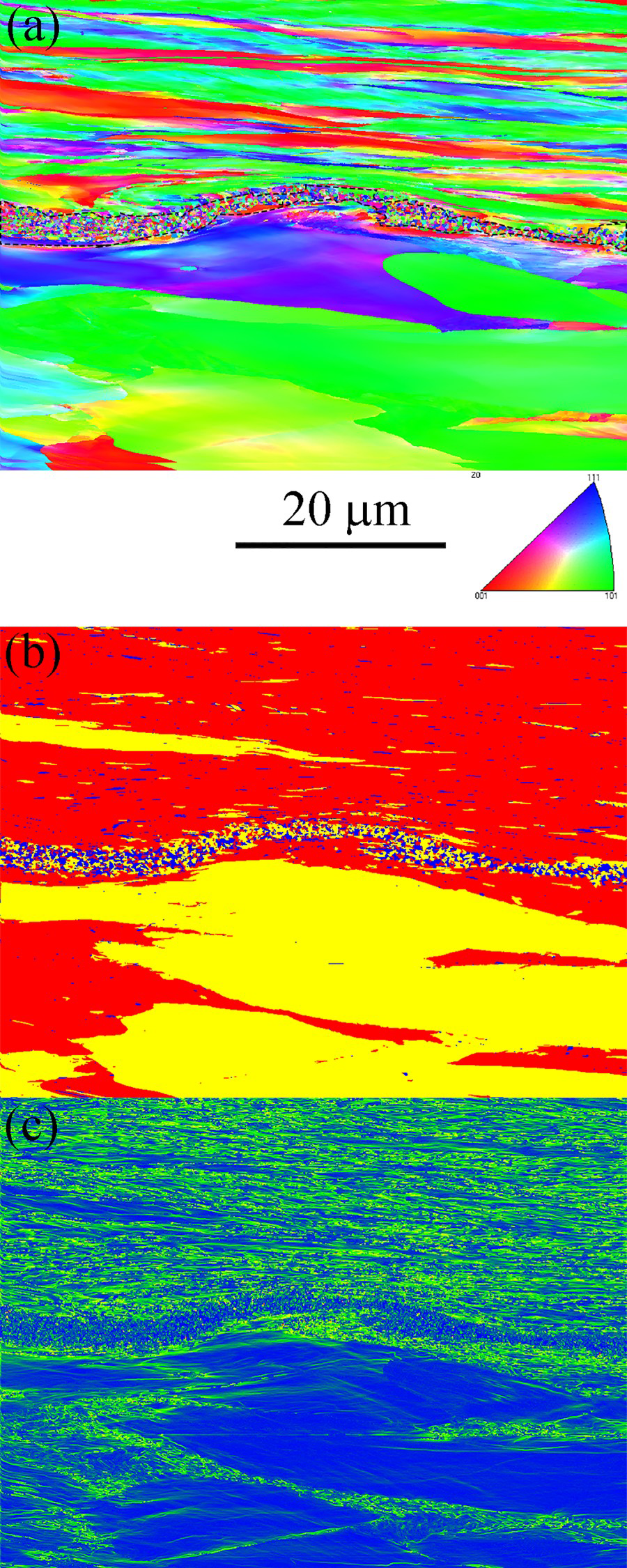
EBSD tests were conducted to further study the microstructure of the interface near the transition layer, and the corresponding results are shown in Figure 8. From Figure 8 can be clearly seen in the explosive welding process of high-speed collision welding, the grain structure near the interface has changed significantly. The transition layer produced at the interface between copper and steel, clearly visible in the 1–2 μm width of the fine grain layer, as shown in the black dashed line. The percentage of nanocrystals below 400 nm in the EBSD test region is as high as 76%, and these fine grains are concentrated in the transition layer and exhibit a uniform isometric crystal, with smaller grains in this region than those formed at any other location (Figure 10). The formation of this feature is due to extremely high heat and large deformation near the interface, which causes dynamic recovery and recrystallisation in the transition layer [32, 33]. The results of the recrystallisation distribution in Figure 9(b) and the results of the local misorientation (KAM) in Figure 9(c) provide evidence of dynamic recovery and recrystallisation, demonstrating that large plastic strains occur in the material adjacent to the interface, while the local misorientation in the transition layer is low due to high temperature effects [34]. In this case, the newly formed ultrafine grains in the transition layer nucleate directly from the liquid and their growth is inhibited by the rapid cooling process [12, 35]. It should be noted that the region where this fine-grained transition layer appears corresponds to a much smaller waveform amplitude than the one that corresponded to it previously in the case of welded Cu/Fe plates [36]. In addition to the longitudinal oblique collision process, circumferential tensile deformation occurs during the expansion of the tube. The combined effect of these two motion processes may be the reason for the formation of the small wave interface. The smaller amplitude and larger wavelength increase the contact area with the copper substrate, while the high thermal conductivity of copper facilitates the rapid cooling of the interface, resulting in fine grains [37]. In contrast to the Cu substrate, only a small amount of refined grains were detected on the Fe side near the interface. Instead, a grain deformation layer with significant curvature characteristics was formed on the Fe side near the interface along with the wave interface. This is due to the fact that during the formation of the interface, according to the Bahrani-Black-Crossland indentation mechanism, the material near the interface experiences interactions of jets in different directions, leading to perturbations of the interface [35, 38, 39]. It should be noted that in previous studies on welding of plate, highly curved grains were also observed near the interface [17]. The grains at the material matrix away from the interface have a columnar structure without deformation or recrystallisation, which indicates that the underwater explosive welding process of the tube still has solid-state welding properties that do not affect the properties of the matrix material. This property is consistent with the dimensional change in Figure 2 and the hardness change in Figure 5.
The statistical results corresponding to EBSD region: (a) grain size, (b) misorientation.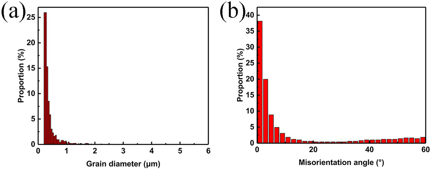
Conclusion
Underwater explosion welding process is employed to joining copper/steel tube. After explosive welding, composite tube distortion is small and no damage to the surface. Copper/steel interface appears fine crystal layer and a high hardness, thus the underwater explosive welding composite tube process is conducive to improving the interface bonding strength to fabricate high-performance composite tube.
Footnotes
Disclosure statement
No potential conflict of interest was reported by the author(s).