
Abstract
Wire arc additive manufacturing (WAAM) process is widely used in large steel components. However, WAAM severe heat accumulation reduced the accuracy of the products, its microstructure and mechanical properties also deteriorate. Compared with common steel, it is more difficult to get complicated stainless steel components with WAAM due to its weak heat dispersion. To efficiently mitigate the heat accumulation, this paper presented a water-medium active cooling additive manufacturing system to complete a 304 stainless steel thin-walled structure. As a result, taller and narrower thin-walled parts could be gotten with 7% increase in average height and 13% decrease in average width. Simultaneously, the surface waviness is reduced, grains are refined and fracture properties of thin-walled parts are improved.
Introduction
Additive manufacturing (AM) is a technology for manufacturing complex three-dimensional objects by stacking layers, which allows for flexible distributed manufacturing, multiple material combinations and shortened processes [1-3]. Wire arc additive manufacturing (WAAM) is considered to be the most suitable candidate for manufacturing large components with relatively simple shape because of the high deposition rate, low cost and good material adaptability [4, 5]. WAAM has been successfully implemented for producing some large components in the fields of aviation, aerospace and ships [6]. Three kinds of heat resources are often used in WAAM and they are tungsten inert (TIG), metal inert gas (MIG) and plasma arc welding (PAW) [7
Austenitic stainless steel has been widely used in aerospace, marine, chemical and nuclear industries because of its outstanding corrosion resistance and mechanical properties in room and elevated temperature [12]. To pursue high production efficiency, high energy deposition of metals is often required. However, the thermal conductivity of stainless steel is only one-third of carbon steel, and the microstructure of stainless steel is more sensitive to the thermal cycling process [13]. The repeated heating and cooling during high power deposition makes it difficult to stabilise the microstructure and properties of austenitic stainless steels. Meanwhile, the heat input is much greater than the heat dissipation, which can also lead to deviations in product dimensions and even failure [14-19]. It is found that with the accumulation of parts, more and more heat can only be lost to the surrounding atmosphere through thermal radiation and thermal convection [20], which are far less efficient in heat transfer than heat conduction. Therefore, the upper layers of metal will be more difficult to shape as the number of layers increases. Without proper thermal management strategies, the flow behaviour of molten droplets and pools will be difficult to control, thus affecting the integrity and performance of the product.
To reduce the heat accumulation effect, researchers usually use methods that increase the dwell time between layers [21]. The approach keeps the deposited layer surface at a lower temperature before deposition and therefore prevents heat accumulation. However, due to the increased interval between layers, the production efficiency of the product is significantly sacrificed [22]. To optimise the cooling efficiency, several methods have been used to accelerate the heat dissipation process. One special idea is based on thermoelectric active cooling technology. This method converts thermal energy into other forms of energy and compensates the residual heat in the molten pool with additional cooling, saving 42% to 54% of the interlayer dwell time [23]. The most popular method is achieved by accelerating the thermal convection between the gas and the part. Jetting cold air or CO2 cooling gas is applied in the interlayer cooling process of WAAM [20, 24], which not only optimises the cooling conditions in production but also slightly improves the performance of the product. Owing to the limited rate of heat dissipation by thermal convection, neither extended interlayer cooling time nor active gas cooling methods can solve the problem of heat accumulation during high power deposition. More efficient method is proposed by introducing a liquid cooling medium to change the form of heat exchange. Initially, the workpiece is deposited on a substrate with the lower half immersed in water [25], which can improve the quality of thin-walled parts with few layers. However, the cooling effect became gradually worse as the number of layers increased. The concept of near-immersion active cooling (NIAC) is thus proposed [26]. NIAC can actively control the rise of water level. With the method the aluminium alloy wall was made which has stable dimension and low porosity without dwell time.
Theoretically, the NIAC method allows the majority of heat to be transferred to the cooling medium in the form of heat conduction, maximising the speed of the heat exchange process. Meanwhile, NIAC coolant is cost effective, recyclable and worth applicating to other higher heat input depositing methods. At present, NIAC mainly assists in the deposition of aluminium alloys with low-power CMT additive manufacturing process [26-30
The NIAC technology is used in producing stainless steel thin-walled parts through WAAM with high-power MIG process in this paper. The effects of water cooling conditions on the forming efficiency, microstructure, mechanical properties and fracture behaviour of the products are studied.
Experimental procedure
Experimental setup and working principle
The experimental tests are carried out with a robot welding system and NIAC system. Figure 1 shows the schematic diagram of the GMAW-based additive manufacturing system.
WAAM system with an auxiliary cooling device.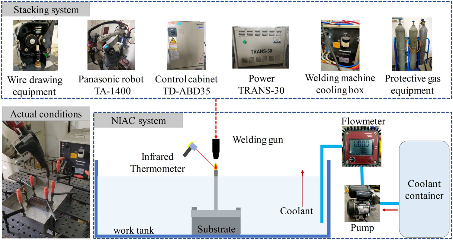
The main equipment of the stacking system includes six-axis Panasonic robot TA-1400, TD-ABD35 control cabinet, TRANS-30 power source, welding machine cooling box, wire drawing equipment, protective gas equipment and workbench. The welding torch is connected to the robot and moves by according to the controller. The substrate is fixed in the centre of the work tank by the clamping device, and the robot controls the welding gun to perform cladding on the surface of the substrate. During the deposition process of the active cooling experiment, the robot travels according to the program setting. At the same time, the pressure vessel pumps the coolant into the work tank at a preset flow rate to ensure that the liquid level is kept at a certain distance from the highest cladding layer. After each layer has been deposited, the robot and the water pump will stop working until the top surface temperature of the workpiece has cooled to a safe temperature [24, 31], and then they will be turned on at the same time. During the cladding process, the upper surface temperature is measured using an IR thermometer and the dwell time is thus controlled between deposition of the layers.
Material and process parameters
ER304 element composition.
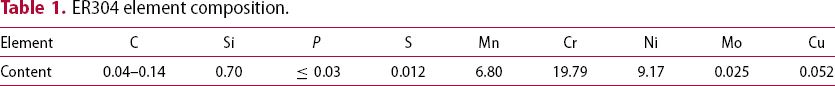
Deposition assignment.
Deposited parts and sampling methods
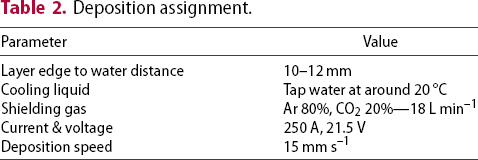
Deposited walls with water and air cooling method are shown in Figure 2. Both deposited parts use the same process parameters and reciprocating path to deposit 60 layers.
Deposited walls with water and air cooling method.
To compare the cooling effect, several specimens were removed from the wall for analysis and evaluation. The schematic diagram of the sampling location is shown in Figure 3.
Sampling position of tensile parts.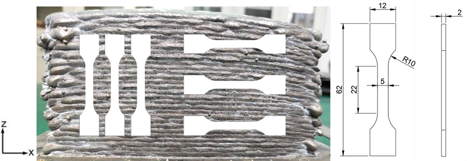
Three X-axis (transversal) and three Z-axis (longitudinal) tensile specimens as well as several metallographic specimens are taken from each thin wall. The microstructure of the metallographic specimens is analysed by optical microscopy. In the tensile test, the universal mechanical testing machine KY-100KN is used for the test, all tests are performed at room temperature with a stretching rate of 2 mm min–1. During the hardness test, the maximum load of the diamond-shaped indenter is 100 g and the holding time is 15 s.
Results and discussion
Deposition geometry and efficiency
The unstable size due to excessive flow of the molten pool is a visual expression of the heat accumulation effect. The cooling effect of the two methods is characterised by the width–height distribution and surface waviness. The height distribution of the thin-walled parts under the two cooling methods is shown in Figure 4. The morphology of the deposited layer depends on the competition of melt pool flow and solidification rate. With the influence of cooling water, the melt pool temperature gradient increases, prompting an enhanced Marangoni effect of Molten pool flow, but at the same time the solidification rate of the liquid metal is accelerated. The thin-walled parts all undergo reciprocal path deposition, showing low sides and high centre, but the NAC method has severe undercuts at the ends of the parts. From the results it is clear that the NIAC piece is higher than the other, indicating that the active cooling method of the high power WAAM overcomes the Marangoni effect and makes the shape more stable.
Height distribution of thin-walled parts.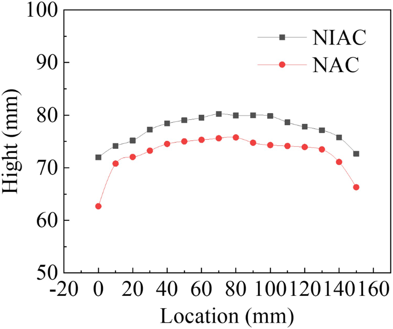
Figure 5(a and b) shows the vertical section morphology of the steel wall deposited under different cooling conditions. In the vertical cross-section of the two walls, the deposited layers regularly form a ‘braided’ state deflected to the sides. This condition may be a special phenomenon caused by the periodic rotation of the welding wire with the sixth axis of the robot. The water-cooled parts in Figure 5(c) are relatively uniform without excessive flow, whereas the overflow phenomenon in Figure 5(d) is obvious. The average height of the thin wall deposited by the active cooling method is 77.34 mm and the width is 7.88 mm, while the average height of the part under air cooling conditions is 72.69 and the width is 8.96. In comparison, the height of the part deposited by the NIAC method increased by 7% and the width decreased by 13%. To further characterise the dimensional accuracy of the thin-walled parts, the surface waviness is defined; Figure 5(e and f) are the outer contours of the two thin-walled parts, and the largest rectangle tangent to the inner contour is taken at the middle position.
(a and b) Overall and partial vertical section. (c) is a partial enlargement of the NIAC part, (d) is a partial enlargement of the NAC part, (e) is the outer contour of the NIAC part, (f) is the outer contour line of the NAC part.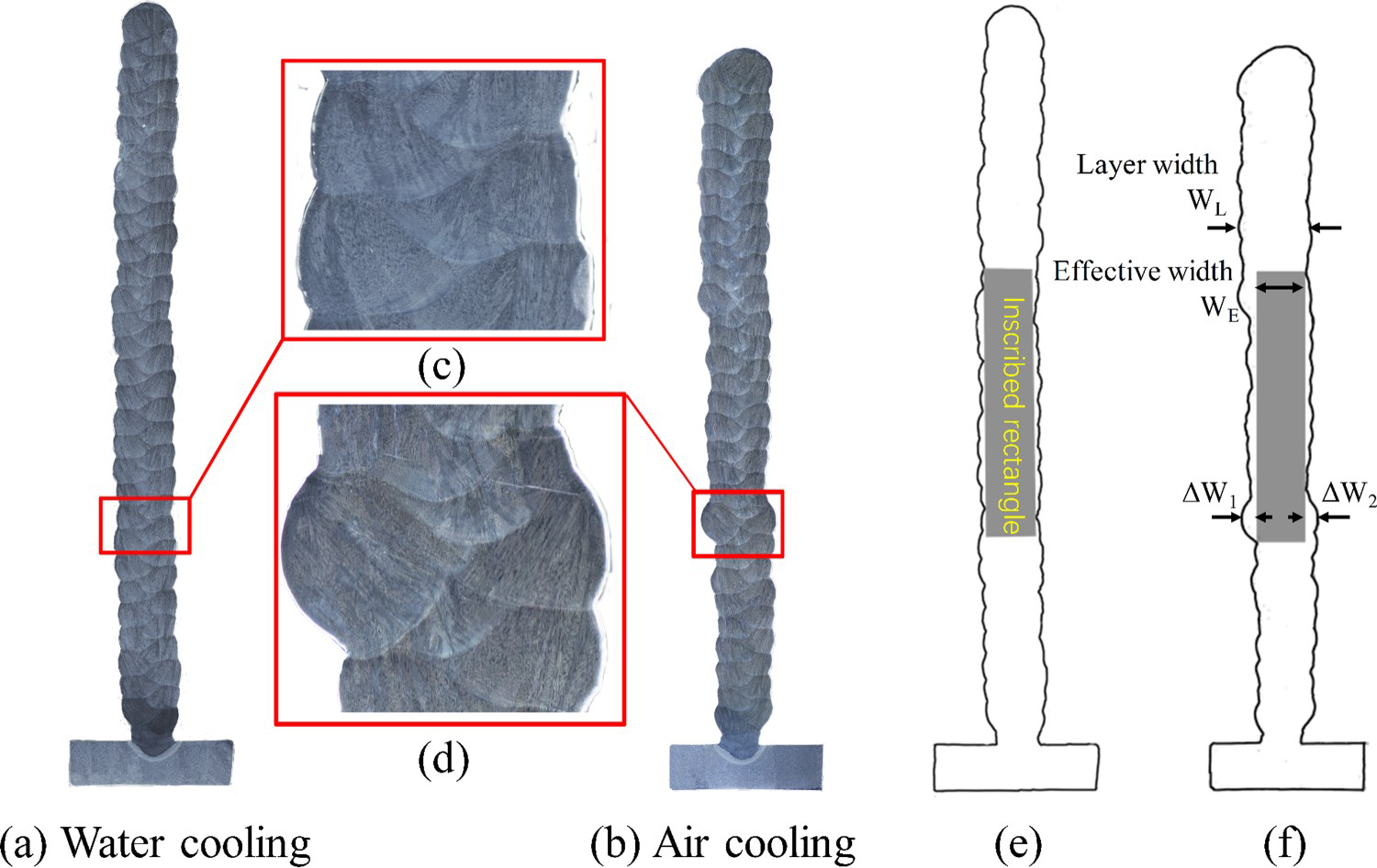
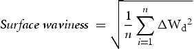
The width of the rectangle is defined as the effective width of thin-walled parts, and the calculation formula for surface waviness is

The image in Figure 6 shows the elapsed time for each layer to cool to 120°C under two different processes. It can be seen from the figure that the time required for each layer of the active cooling method to cool to a specific temperature gradually increases from a lower value and reaches a peak value of about 80 s, then gradually decreases and finally stabilises at about 40 s; NAC methods require much longer cooling time than water-cooling methods. As the number of layers increases, the time required for cooling also increases greatly. The final cooling time is stable at about 480 s, which is 12 times of active cooling methods. The NIAC method consumes less than one-ninth of the time to complete a 60-layer deposition as the NAC method, which means that NIAC has a high engineering value in the efficient deposition of stainless steel.
The inter-pass cooling time for fabricating wall parts with active cooling and air cooling.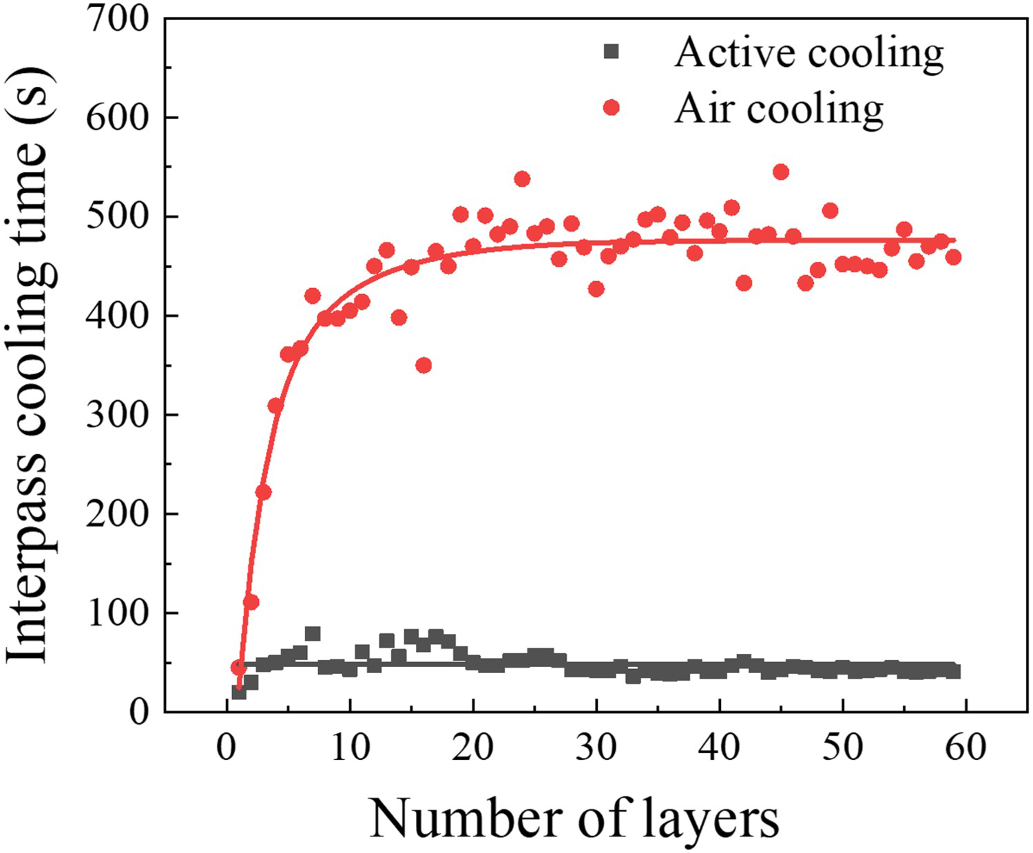
Metallographic analysis
To investigate the possible negative metallurgical effects of water vapour under NIAC conditions, the microstructure and defect distribution under the two conditions are compared. The vertical cross-sectional microstructures of the thin-walled parts under both cooling conditions are shown in Figure 7.
Macroscopic and microscopic microstructures of longitudinal sections of thin-walled parts under NIAC and NAC conditions (two dividing lines are formed between the layers, marked with red and green dotted lines respectively. The yellow dashed lines outline the two columnar crystals under the NIAC and NAC methods).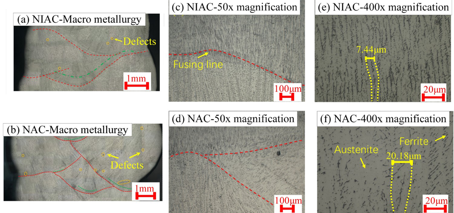
Although the interlayer dwell time of NIAC can reduce the influence of water vapour to a certain extent, the negative effect that water vapour may bring to the product cannot be ignored. Therefore, defects and porosity in the macroscopic metallographic structure of the product under both conditions are marked to determine the sensitivity of defects under both processes, as marked with yellow circle in Figure 7(a and b). The results show more defects and porosity under air-cooled conditions, while only a small amount of porosity under water-cooled conditions, which indicates that the porosity of the part does not increase under NIAC conditions.
Figure 7(a and b) both show the presence of two re-melting lines in the same cladding layer. The formation of this particular phenomenon can be explained by the special behaviour of the melt drop transition, when the melt droplet on the wire just enters the molten pool, a large crater appears on the cladding layer because of the large arc pressure re-melting (the bottom of this crater is marked by a red dotted line) as shown in Figure 7(a and b). As the arc moves toward the cladding path, the metal on the crater begins to solidify rapidly, and then the melt droplets fall off the wire and carry heat into the molten pool, where the re-melting phenomenon reappears again. Comparing the relative positions of the red and green lines, it can be found that the green dotted line in the NIAC condition is more complete and the distance between the two re-melting lines is wider, while the two dotted lines in the NAC condition are close together and partially overlap. This indicates that the NIAC method absorbs more energy at the stage of melt drop transition and reduces the depth of the re-melting pool, explaining why the overall height of the thin-walled parts is higher under NIAC conditions.
Figure 7(c and d) show enlarged views of the cladding boundary. The directionality of the grains can be observed in both methods, but there is a local disappearance of grain boundaries in the NAC part. Figure 7(e and f) are taken from the upper fusion line of the middle section of different thin-walled parts. It can be seen that the microstructures of the two products are mainly composed of austenite columnar dendrites (white) and residual ferrite (black), and the residual ferrite exists at the austenite boundary. The solid-state phase transition of the microstructure occurs according to the FA mode [32]: first, the primary ferrite phase is formed. Then, during the solid phase transformation, they are gradually replaced by the austenite phase. At the bottom of each layer under both processes, there are finer columnar crystals. As the distance from the bottom increases, the grains gradually thicken and secondary dendrites of austenite appear away from the bottom of the layer. It can be seen that the average secondary dendrite spacing under the NIAC method is 3.73μm, which is much smaller than the 10.09μm under the NAC method. Yin et al. also confirmed that the secondary dendrite spacing decreases with the increase of cooling rate [14, 33]. With the addition of cooling water, the heat dissipation state of the straight wall section changes from solid–gas convection to solid–liquid conduction. This change increases the degree of subcooling and accelerates the solidification of the molten pool, resulting in fine and narrow grains.
Mechanical property
To further investigate the effect of the NIAC on the mechanical properties, hardness tests, X-axis and Z-axis tensile tests are carried out. Figure 8 shows the hardness distribution on the centre line of the vertical sections of the wall under two processes.
Vickers hardness distribution.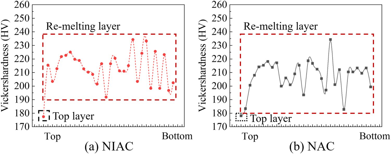
From Figure 8, it can be seen that the hardness on the top layer is lower due to the equiaxed grain. Since the top layer has not been re-melted, the top layer data needs to be removed to analyse the hardness variation pattern. The hardness of the bottom metal layer under both methods has a regular fluctuation phenomenon, the peak of the hardness corresponds to the centre of the clad layer, while the trough is located at the boundary between layers. The hardness of the bottom metal under the NAC method fluctuates much less, which is because the long time high-temperature condition promotes the diffusion of reinforced phase between layers, narrowing the difference between the hardness of the centre and the boundary. Hardness is higher when the indenter of the hardness tester is loaded with multiple grains that are subjected to more hindrance. When there is less distribution of reinforcing phases under the indenter, the hardness decreases. The hardness is relatively stable as the part remains hot for a long time in the air-cooled state, where a tempering-like heat treatment process occurs and the second phase dissolves into the grains. The hardness of the middle and upper parts of both parts increased and then decreased, but the overall hardness under the NIAC method was slightly higher than that under the NAC method, with an average hardness increase of 5 HV. This indicates the NIAC method does not have a significant effect on the average hardness of the product.
The hardness distribution of a single section cannot reflect the overall mechanical properties of the thin-walled part, so the specimens in both X and Z axes are taken for tensile testing. Figure 9(a) shows the average tensile strength and Figure 9(b) shows the displacement stress curves for different regions and directions under two cooling conditions.
Average tensile strength and displacement stress curve.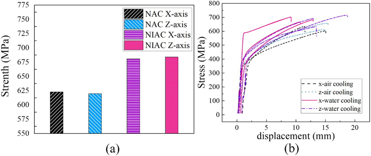
The mechanical properties of WAAM parts are generally weaker in the Z-axis than in the X-axis due to the pronounced directionality of the columnar crystals [4]. However, tensile specimens under the same method have comparable strength in both directions. The reason may be that the unique ‘braided’ structure increases the strength of the Z-axis tensile specimens during the high-power deposition process, thus showing isotropic characteristics. The average ultimate tensile strength of the air-cooled sample is 622 MPa, while the ultimate tensile strength of the sample under the water-cooled condition rises to 683 MPa. It can be explained that the shrinkage of the secondary dendrite spacing and the dispersion strengthening of the second phase under water cooling conditions can effectively improve the mechanical properties of the wall. It should be noted that although the strength is increased, the elongation of the sample will be reduced.
Fracture behaviour
The fracture characteristics can visualise the reason for the difference in mechanical properties and help to analyse the strengthening mechanism of the specimens under NIAC conditions. Figure 10(a and b) show the fracture morphology of the X and Z axes of the part under air cooling condition. Figure 10(d and e) show the fracture morphology of the X and Z axes of the part underwater cooling condition. It is observed from Figure 10(f) that the fracture has a clear dimple morphology, which is a typical ductile fracture, and a certain second phase particle is found in the centre of the dimple.
Fracture morphology characteristics.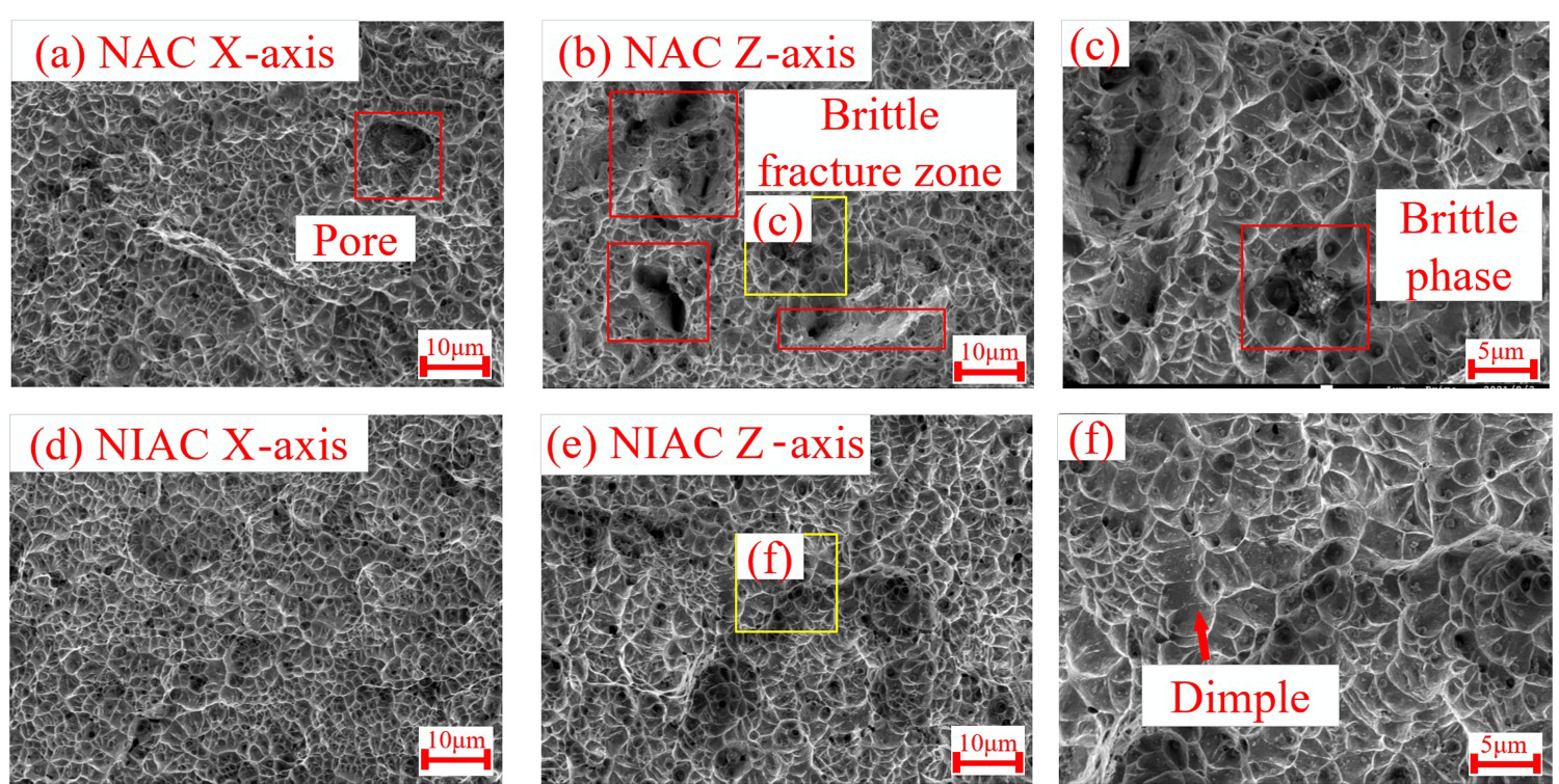
Owing to the difference in elasticity and plasticity between the second phase and the matrix (the binding force of the second phase and the matrix, the thermal expansion coefficient, the size of the second phase particles themselves, etc.), micropores are generally formed at the second phase first during the stretching process. Comparing the X-axis fracture morphologies in Figure 10(a and b), it can be found that the fracture morphology of the NIAC components is all small dimples, whereas there are large holes under the NAC. The longitudinal fracture morphology under the two heat dissipation conditions is different. There are many brittle fracture areas in the port under the air cooling condition. We can see in Figuer 10(c) that there is a clear aggregation of brittle phases in the red box. This is due to the long residence time of NAC parts at high temperatures, which leads to the precipitation and aggregation of harmful elements, resulting in local brittle fractures. In contrast, the fracture morphology of the thin-walled NIAC parts was homogeneous and no localised areas of brittle fracture were observed.
Conclusion
A liquid cooling platform for wire arc additive manufacturing is built with the active water cooling system, by which thin-walled 304 stainless steel structures were made. The following conclusions are reached.
The active water cooling method can effectively relieve the heat accumulation in the high-power arc additive manufacturing process, requiring only 1/12th the interlayer cooling time of natural air cooling to dissipate the same amount of heat. The natural cooling method has localised excessive flow in the molten pool during deposition, but the forced liquid cooling method can suppress the flow of the molten pool and reduce the re-melting depth, so that the overall width of thin-walled parts decreased by 7%, and the height increased by 10%. The regular offset of the cladding to the sides increases the surface waviness, but it improves the anisotropy of the arc additive manufacturing product. Active cooling method can refine the grain, reduce the precipitation of brittle phase caused by superheat, increase the average tensile strength of thin-walled parts from 622 to 683 MPa, significantly improving the performance of high-powered wire arc additive manufacturing products.
Footnotes
Data availability statement
All data generated or analysed during this study are included in this manuscript.
Disclosure statement
No potential conflict of interest was reported by the author(s).