
Abstract
In vacuum laser welding, a laser beam is irradiated into a chamber through a coupling glass exposed to contamination. A conical protective system for the coupling glass is suggested, and contamination is analysed via simulation and experiments based on the conical component height and the gas flow rate. Stable descending flow is a key to suppressing the contamination, which affects the particle ascending velocity, horizontal deflection of particles and number of residual particles. The laser transmission area can be protected using a gas flow rate of 1.0 L min−1 or a cone height of 90 mm for the conical component. The conical protective system demonstrates excellent contamination suppression capability. The simulation-based approach can provide an effective design for the protective system.
Keywords
Introduction
A high welding penetration depth and a low heat input are key aspects in laser welding. In the last two decades, vacuum laser beam welding (VLBW) has garnered significant interest [1-3]. Because VLBW is implemented under subatmospheric pressure, the boiling temperature of the material decreases, and sound deep penetration welding can be achieved owing to stable keyhole behaviours [4, 5]. Furthermore, a reduced ambient pressure causes less plasma and plume formation, which can reduce the interaction between the process laser beam and the plasma plume [6-8]. Observations of the weld pool and numerical simulations revealed that the upward flow along the rear keyhole wall in the molten pool reduced porosity defects, which are prevalent in deep penetration welding [1, 9-13].
In the earliest stage, VLBW was implemented using a CO2 laser [14, 15], which was then replaced by optical-fibre-deliverable lasers such as Nd:YAG, disk and fibre lasers. A fibre-delivered laser beam is focused by laser optics and irradiated into the vacuum chamber through a coupling glass, also known as a guard glass [6], an aperture window [16], a protection glass [9], a vacuum window [17], a transmission window [18] or a glass window [19]. Similar to the cover glass for open laser optics used in atmospheric pressure laser welding, the coupling glass protects the laser focusing optics from contamination by spatters and fumes. The contamination of the coupling glass or cover glass can result in thermal lensing, laser focus shift, and, in severe cases, glass breakage [20]. In VLBW, coupling lens contamination is a critical issue because the welding chamber is enclosed. Maintenance of the coupling glass is indispensable for ensuring quality consistency, and the maintenance period is one of the factors that determines the process productivity.
However, most studies regarding VLBW have only focused on the welding phenomenon instead of the coupling glass and its protection. Furthermore, protection systems including the coupling glass have not been investigated hitherto, except in our previous studies [21, 22]. In some studies, a cylindrical protective system and/or shielding gas supply have been adopted; however, the protection mechanism was not the research focus, and the protection mechanism was not investigated comprehensively. Reisgen et al. reported that the protection of the coupling glass is crucial to the welding stability, and that the welding quality was consistent for more than 150 welding trials without cleaning or changing the coupling glass by applying an appropriate protection system [16]. In a subsequent study, they developed a protective system known as ‘OptiShield’, which enabled more than 1000 welding trials per window [23, 24]. However, the details of the protective system employed were not reported. In general, a cylindrical protective system was used when required, and N2 or Ar gas was supplied to a gas curtain under the coupling lens.
The protective system was investigated both experimentally and analytically. In the experimental approach [21], the contamination index was defined using the coupling glass transmittance. The glass contamination behaviour was quantitatively investigated based on the shielding gas flow and gas nozzle diameter. In the analytical approach [22], a computational fluid dynamics model was developed to simulate fume particle movement and glass contamination. In the simulation, the cylindrical protective system and horizontal gas supply inside the protective system were modelled as in the experiments. The glass contamination predicted by the developed numerical model was consistent with the experimental results. The shielding gas supply formed dead zones caused by vortices near the bottom edge of the protective system, which inhibited the efficient discharging of welding fumes from the protective system. In the range of the simulated shielding gas flow rate and gas nozzle diameter, the internal flow field for all cases was insufficient to eliminate the dead zones. Therefore, approaches other than modifying the gas supply parameters must be identified.
In this study, we propose using a conical-shaped protective system with no edge at the bottom instead of a cylindrical protective system. Based on the numerical simulation model, the streamline of the fluid flow and the trajectory of the fume particles were investigated based on the height of the cone-shaped component and the shielding gas flow rate, and the fume particles that adhered to the laser transmission area were evaluated quantitatively. The effects of the driving forces in suppressing fume adsorption on the coupling glass were discussed based on simulated particle trajectories. The reliability of the numerical model was evaluated based on a comparison between numerically simulated contamination and experimentally measured results.
Methodology
Experimental condition
The vacuum chamber and optic system used to perform VLBW are shown in Figure 1. A fibre laser with a wavelength of 1070 nm and a maximum power of 3 kW was used in the experiment. A laser beam was transmitted through a fibre whose diameter was 200 µm and focal length was 300 mm. A laser beam was perpendicularly irradiated on the base materials through the coupling glass from outside the chamber. The diameter of the laser transmission region on the coupling glass was 10 mm, and the diameter of the entire effective area of the coupling glass was 39 mm.
The vacuum laser beam welding (VLBW) system.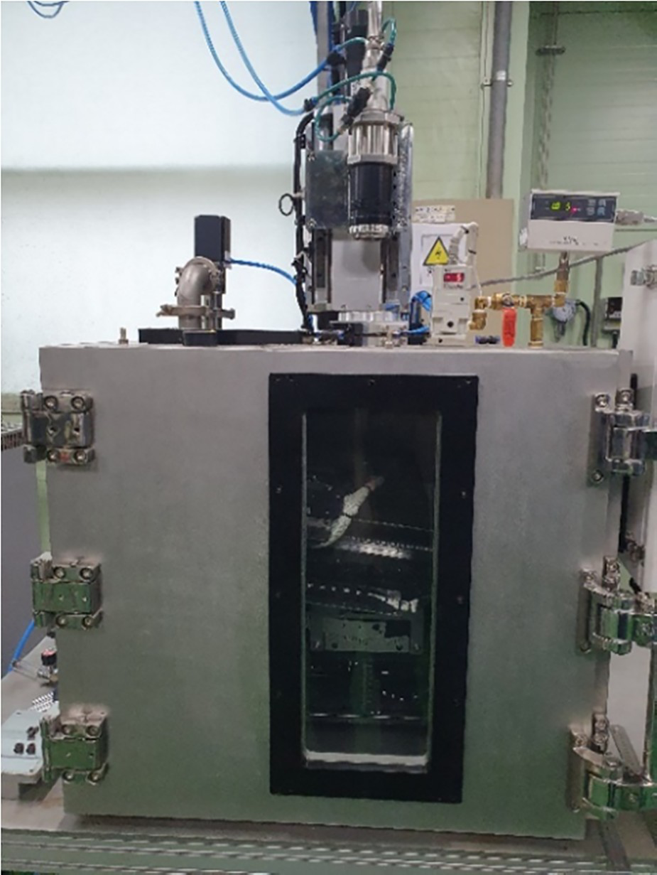
A protective system was installed below the coupling glass (Figure 2(a)) to prevent the contamination of the coupling glass by fumes and spatters. N2 shielding gas was supplied through a cylindrical nozzle whose diameter was 4 mm at the upper wall of the protective system. The shielding gas was supplied perpendicular to the direction of the laser transmission. The capacity of the vacuum chamber was 168 L, and the working pressure inside the chamber was maintained at 1 kPa during welding.
Schematic diagram of protective system in VLBW. (a) Coupling glass and protective system; (b) simulation domain.
The protective system applied in this study had a cylindrical top component and a conical bottom component. The height of the frustum, Hf, is an important parameter in addition to the gas flow rate. In this study, Hf included an aperture height of 8 mm and was varied as 50, 70 and 90 mm, whereas the gas flow rate was set to 0.5 and 1.0 L min−1. The shielding gas was supplied by the laser irradiation.
The base material was galvanised steel sheets with a thickness of 1.4 mm and Zn coating layers with a weight of 79 g m−2 on both sides. Because Zn evaporation from the coating layers accelerated fume generation, the glass contamination can be evaluated based on a relatively short welding length. The welding trials were performed for 5 s with a laser power of 600 W and a welding speed of 1.0 m min−1. The distance between the base material and the bottom of the protective system was fixed at 3 mm.
After welding, the transmittance of the coupling glass was quantified using a spectrum transmission meter with an IR peak wavelength of 940 nm and a resolution of 0.1%. The measured transmittance was converted to the contamination index using the following equation:

Numerical analysis
The momentum and continuity equations were solved to analyse the flow field and particle behaviour in the protective system using the commercial computational fluid dynamics software, Flow3D. The gas phase flow field that simulated the behaviour of the nitrogen (N2) shielding gas and air in the protective system was analysed via a two-fluid analysis. The fume particle trajectory was determined by the pressure field of the gas phase and gravity. The detailed equations and assumptions for the flow field analysis and the interaction between the gas phase and particles are described in a previous paper [22].
The pressure boundary conditions are presented in Figure 2(b). Only the aperture region on the bottom plane was involved a stagnation pressure boundary condition, whereas the other planes were imposed with wall boundary conditions. The initial pressure inside and outside the protective system was 1 kPa. Fume particles were generated in the aperture region at a generation rate of 1 kHz. The diameter, initial velocity and drag coefficient of the fume particles were assumed to be 1 μm, 340 m s−1 and 0.47, respectively. Justifications for these assumptions are available in the literature [22].
Figure 3 shows the three-dimensional (3D) numerical calculation domain and meshes used to calculate the particle trajectory based on the shielding gas supply. After calculation, the particle locations were indicated in the centre plane of the XZ-plane, where the Y-coordinates of the particles were visualised through a colour map. A heat map and streamline of the gas fluid flow were visualised based on the same plane [25]. Particle adsorption onto the coupling glass was analysed on the top surface of the XY-plane, and particles in contact with the coupling glass were indicated as contamination. The number of particles adsorbed within the laser transmission region for the initial 5 s in the simulation was compared with the contamination index measured in the experiment.
3D numerical model and meshes: model (left), mesh model on XZ-plane (middle), and mesh model on projection of XY-plane (right).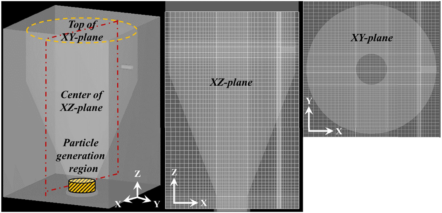
The following characteristics were analysed from the particle and gas fluid behaviours to account for the contamination suppression mechanism: the discharging velocity of the shielding gas across the aperture, particle ascending velocity within the protective system, horizontal deflection of the particles and the total number of particles remaining in the protective system.
The discharging velocity was analysed for the entire aperture region (region 1 in Figure 4). The average velocity was calculated at every 0.1 s during 1.5 s after the shielding gas supply. For the particle ascending velocity, the average velocity of the particles in region 2 shown in Figure 4 was plotted every 0.025 s for 1 s after the shielding gas supply. The analysis area selected excluded the upper cylindrical component to minimise the effect of horizontal deflection due to the shielding gas supply. The horizontal deflection effect was analysed in Region 3 shown in Figure 4. The average velocity in the X-direction was calculated for the first 50 particles passing through the analysis region to prevent interference from the re-entrainment particles by the internal flow circulation. The total number of particles within the protective system was counted after 5 s of simulation. In addition, the number of active particles with momentum was analysed to exclude the number of stationary particles on the walls.
Analysis domain for fume adsorption mechanism.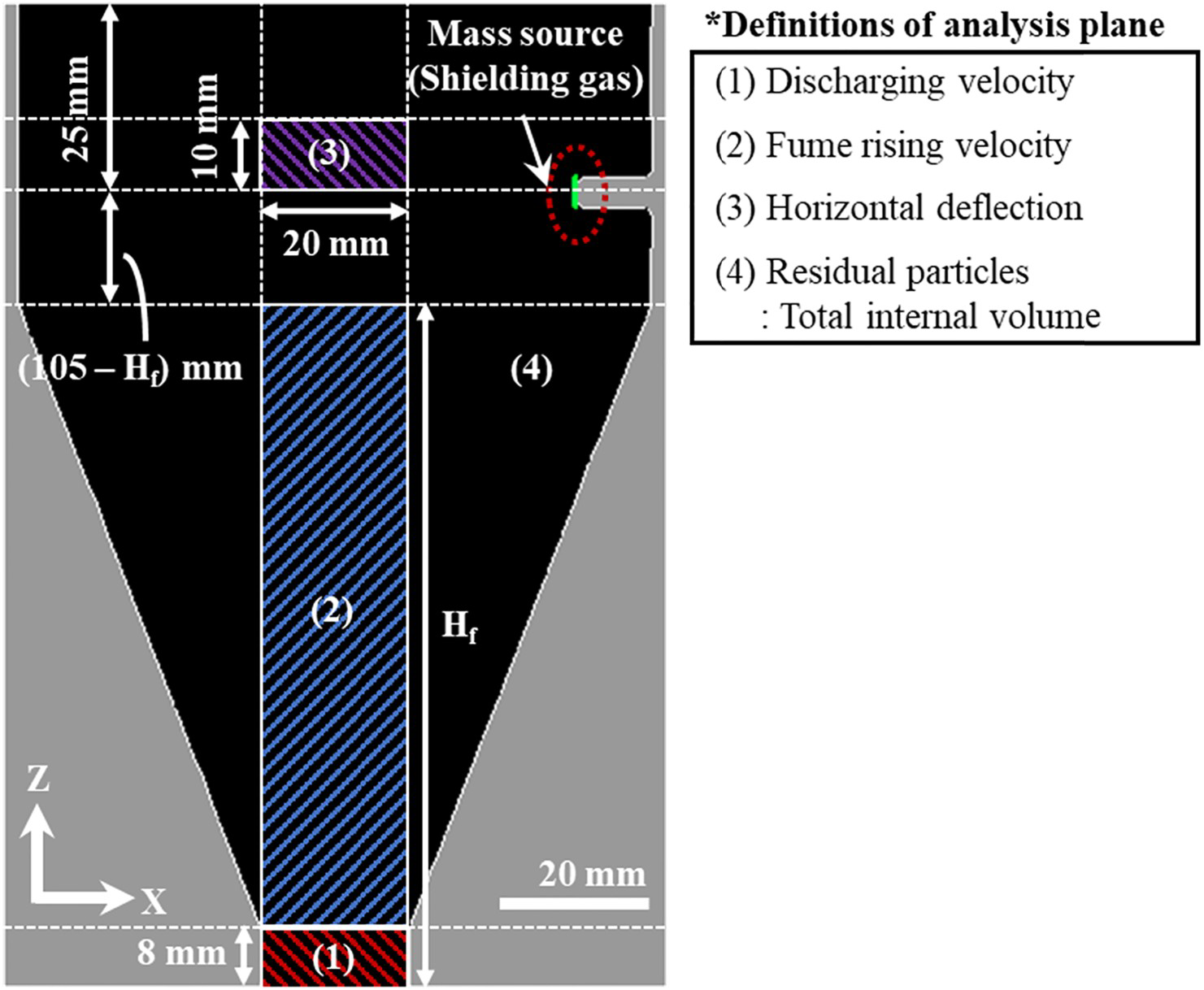
Results and discussion
Fluid flow field and particles behaviour
The fluid flow characteristics at the welding start period were compared for the cylindrical and conical protective systems, as shown in Figure 5. The time steps were selected for the left and right plots when the first ascending particle reached 1/6 and 2/6 of the system height, respectively. Comparing the time steps in Figure 5(a,b), the ascending movement of particles in the conical protective system was slower than that in the cylindrical system. In the cylindrical system, a descending flow was observed along the side wall, and the momentum of the fluid decreased at the corner of the bottom plane. In comparison, the descending flow was concentrated towards the aperture in the conical system, and the streamline distribution was dense in the vicinity of the aperture. In the conical protective system, the ascending movement of the particles in the central axis was impeded, and the descending particles along the tapered side wall discharged easily from the system. The size of the vortices causing the internal circular motion of the particles decreased in the conical protective system, which reduced the number of internally floating particles and the possible contact between the particles and the top plane.
Flow field in (a) cylindrical and (b) conical protective system (shielding gas supply: 0.5 L min−1).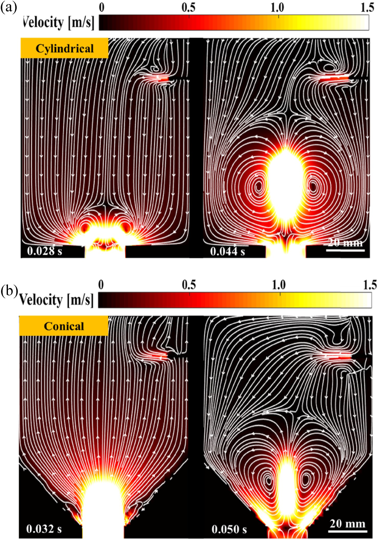
Figure 6 shows the simulation results at time steps of 0.1, 0. 25 and 0.5 s for the case with a shielding gas flow of 0.5 L min−1 and a Hf of 50 mm. At the time step of 0.1 s, an intense ascending flow was formed along the central axis, and a descending flow formed along the sidewall. The top section of the intense ascending flow in the central axis coincided with the location of the particles that were generated in the early time steps. Symmetric vortices and flow circulation were observed at the periphery of the intense ascending flow. At the time step of 0.25 s, the ascending flow interacted intensely with the horizontally supplied shielding gas. The descending flow was formed in the aperture area, which enhanced particle discharge from the system; however, vertices were formed near the top plane, which increased the contact between the particles and the top plane. The early generated particles had already established contact with the top plane, and the particles were clustered in the aperture area owing to the descending flow. At the time step of 0.5 s, the intense ascending flow spanned the entire central axis, and the vertices near the top plane remained. The particles were distributed along the central axis, and a number of particles appeared near the top plane.
Flow and particle behaviour at a gas flow rate of 0.5 L min−1 and 50 mm Hf: (a) Streamline and velocity magnitude and (b) behaviour and distribution of particles.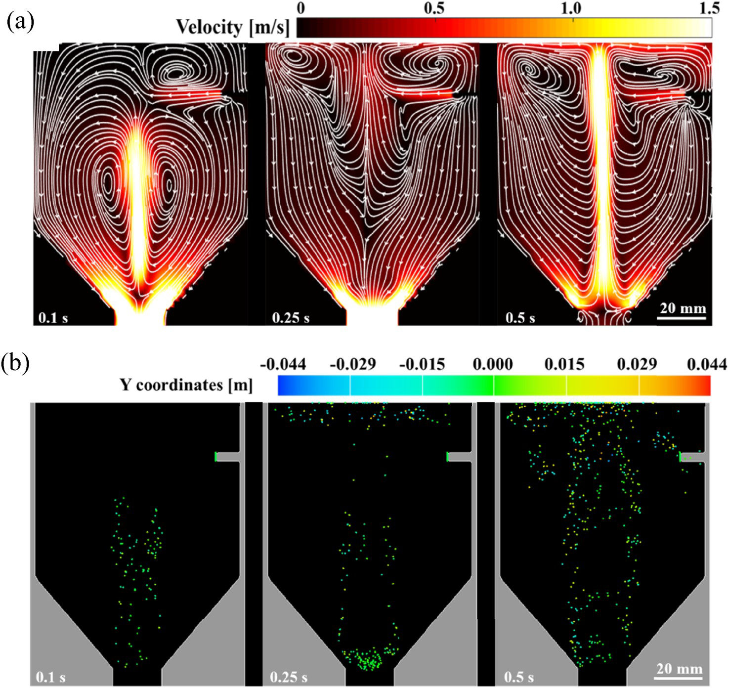
When the gas flow rate was increased to 1.0 L min−1, the ascending movement of the fluid flow was efficiently suppressed, as shown in Figure 7(a). The upper side vortices were deflected towards the side, thereby reducing the contact of the particles in the central region of the top plane. Although a vortex was generated between the gas supply plane and the top plane, the horizontal gas supply prevented most of the particles from approaching the laser transmission area in the centre of the top plane.
Flow and particle behaviour at a gas flow rate of 1.0 L min−1 and 50 mm Hf: (a) Streamline and velocity magnitude and (b) behaviour and distribution of particles.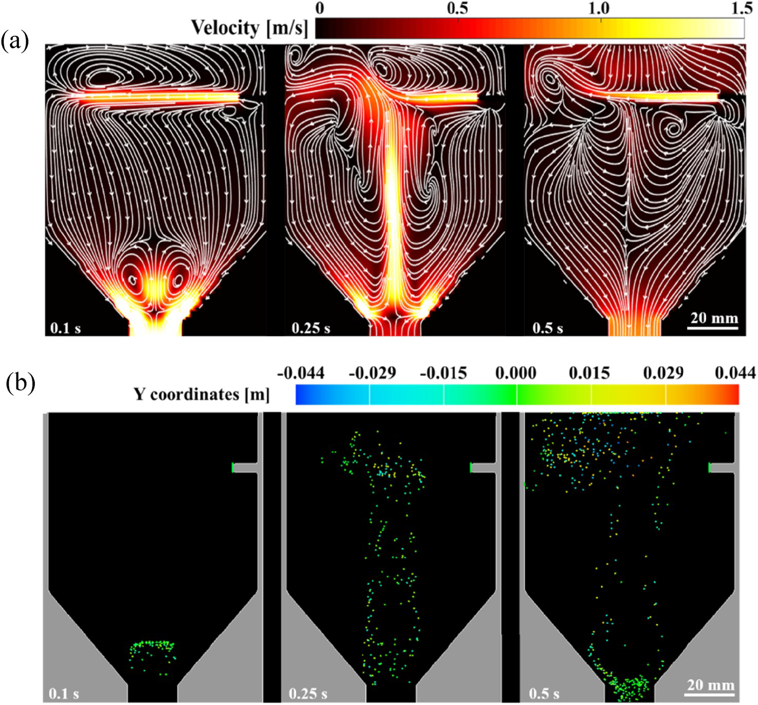
At the time step of 0.1 s, the particles were located much lower than those in the case involving 0.5 L min−1 of gas supply because of the descending flow formed along the central axis due to the gas supply (Figure 7(b)). The size and height of the peripheral vortices located at the lower conical component were smaller than those for the case involving 0.5 L min−1 of gas supply. The particles could not reach the top plane even at the time step of 0.25 s because the ascending flow was suppressed. At the time step of 0.5 s, the particle distribution was extremely dense in the vicinity of the aperture owing to the downward flow. The horizontal deflection of the particles was clearly observed at time steps of 0.25 and 0.5 s.
When Hf was increased to 70 mm at a fixed gas flow rate of 1.0 L min−1, a stable descending flow near the aperture was observed owing to the acute taper angle in the conical bottom (Figure 8(a)), whereas ascending and descending flows alternated near the aperture, as shown in Figures 6(a) and 7(a), respectively. At a time step of 0.1 s, the peripheral vortices located at the lower conical component were not observed because of the high descending flow. Compared with the case of 50 mm Hf, the suppression of ascending flow along the central axis was more evident, and the particles reached a lower height (Figure 8(b)). In addition, the horizontal deflection caused by the shielding gas supply was enhanced, which was clearly observed in the particle distribution at time steps of 0.25 and 0.5 s.
Flow and particle behaviour at a gas flow rate of 1.0 L min−1 and 70 mm Hf: (a) Streamline and velocity magnitude and (b) behaviour and distribution of particles.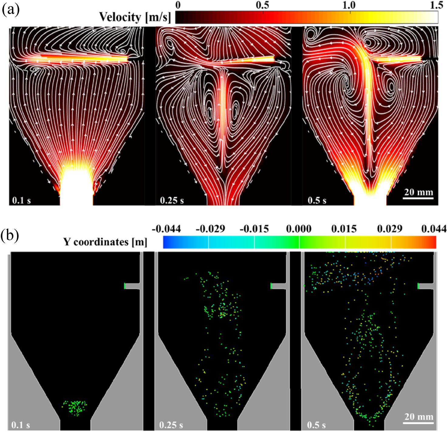
Mechanisms to suppress fume adsorption
The gas discharged from the aperture can prevent the infiltration of fume particles into the protective system. At a gas flow rate of 1.0 L min−1 and a Hf of 50–90 mm, the discharging velocity fluctuated at the start of the welding trials and then stabilised after approximately 0.7 s (Figure 9). In the early stage, the internal gas was discharged rapidly through the aperture, and the magnitude of the fluctuations in the discharging velocity decreased as Hf increased. A lower Hf allowed the fume particles to ascend faster at the early stage (Figures 6 and 7), which generated peripheral vertices and a descending flow along the side wall. However, the discharging velocity stabilised after 0.7 s and converged at approximately 0.05 m s−1 regardless of Hf. Considering the entire welding process time, the effect of the difference in the initial discharging velocity did not significantly affect particle adsorption. In addition, the gas pre-flow prior to the start of welding can reduce the initial fluctuation of the gas discharge velocity.
Discharging velocity based on time and Hf (Gas flow rate: 1 L min−1).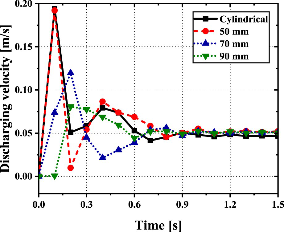
The conical protective system reduced the particle ascending velocity along the central axis of the system (Figure 10). Meanwhile, the decrease in the particle momentum can decrease the possibility of particle adsorption on the laser transmission area at a fixed gas flow rate. The ascending velocity decreased gradually as Hf increased, and the gas flow increased. When Hf was 90 mm and the gas flow rate was 1.0 L min−1, the particles could not ascend upward in the system. Compared with the case of a cylindrical protective system with 1.0 L min−1 shielding gas supply, the conical system with a 90 mm Hf exhibited an 81.7% lower ascending velocity under a 0.5 L min−1 gas supply. As Hf increased, the streamline of the fluid became denser in the vicinity of the aperture, and the ascending motion of particles was disturbed by the descending gas flow. The concentration of particles in the streamline was higher than that in the cylindrical system (Figure 5).
Particle ascending velocity based on the gas flow rate and Hf.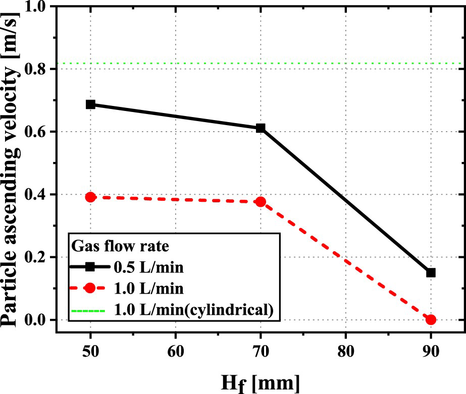
The horizontal gas supply deflected the particle trajectory near the coupling glass from the centre to the opposite side of the shielding gas nozzle, which shifted the particle adsorption location from the laser transmission area to the outside of the laser transmission area or to the outside of the coupling glass. The horizontal deflection of particles in Region 3 (shown in Figure 4) can be determined by the particle ascending velocity and the gas flow rate. By applying a conical protective system, the horizontal deflection increased by 311% with a Hf of 50 mm and 411% with a Hf of 70 mm under a 1.0 L min−1 gas supply (Figure 11), compared with the cylindrical system. When Hf was 90 mm, the deflection could not be evaluated because the particles did not ascend to the upper cylindrical component. When the shielding gas flow rate was 0.5 L min−1 and the Hf was 70 mm, the horizontal deflection was 176% of that in the cylindrical system where the gas flow rate was 1.0 L min−1.
Horizontal deflection of particles based on the gas flow rate and Hf.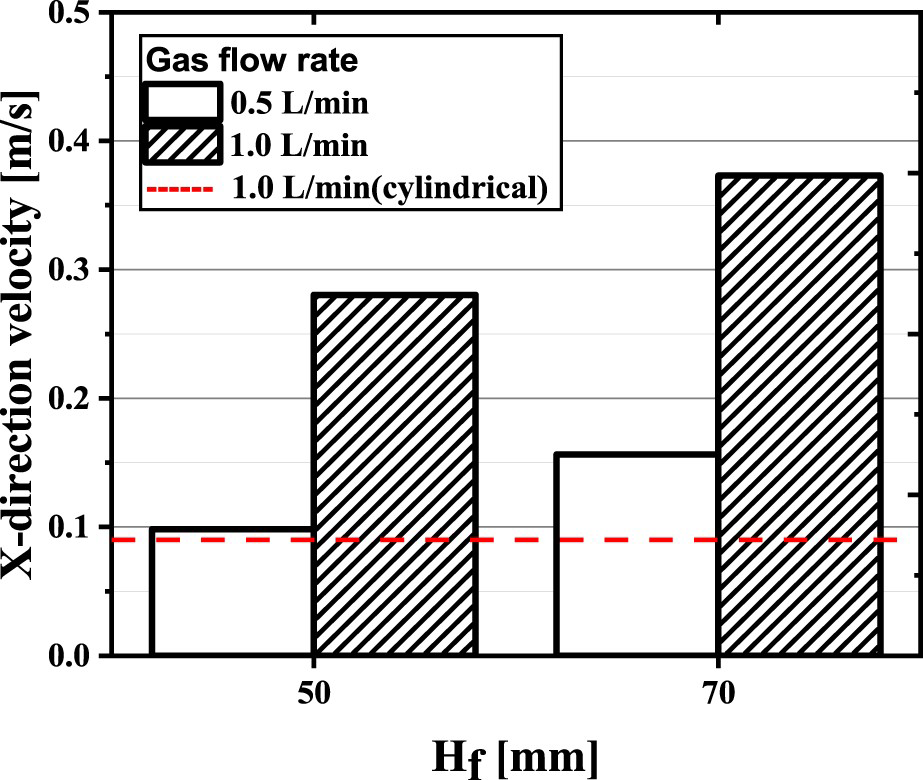
The number of particles remaining inside decreased as Hf increased at a gas flow rate of 0.5 L min−1 (Figure 12(a)). The number of residual particles was similar to that of the cylindrical system when Hf was 50 and 70 mm, and was lower by 13% at a Hf of 90 mm. At a gas rate of 1.0 L min−1, the number of particles decreased with Hf and then increased at 90 mm Hf, which was due to the absorption of particles on the conical bottom wall. As shown in Figure 8, at a high Hf, a dense streamline was formed in the vicinity of the aperture, and a number of particles were adsorbed on the bottom wall.
Residual particles inside protective system: (a) All particles, (b) floating particles with active momentum and (c) relative number of floating particles.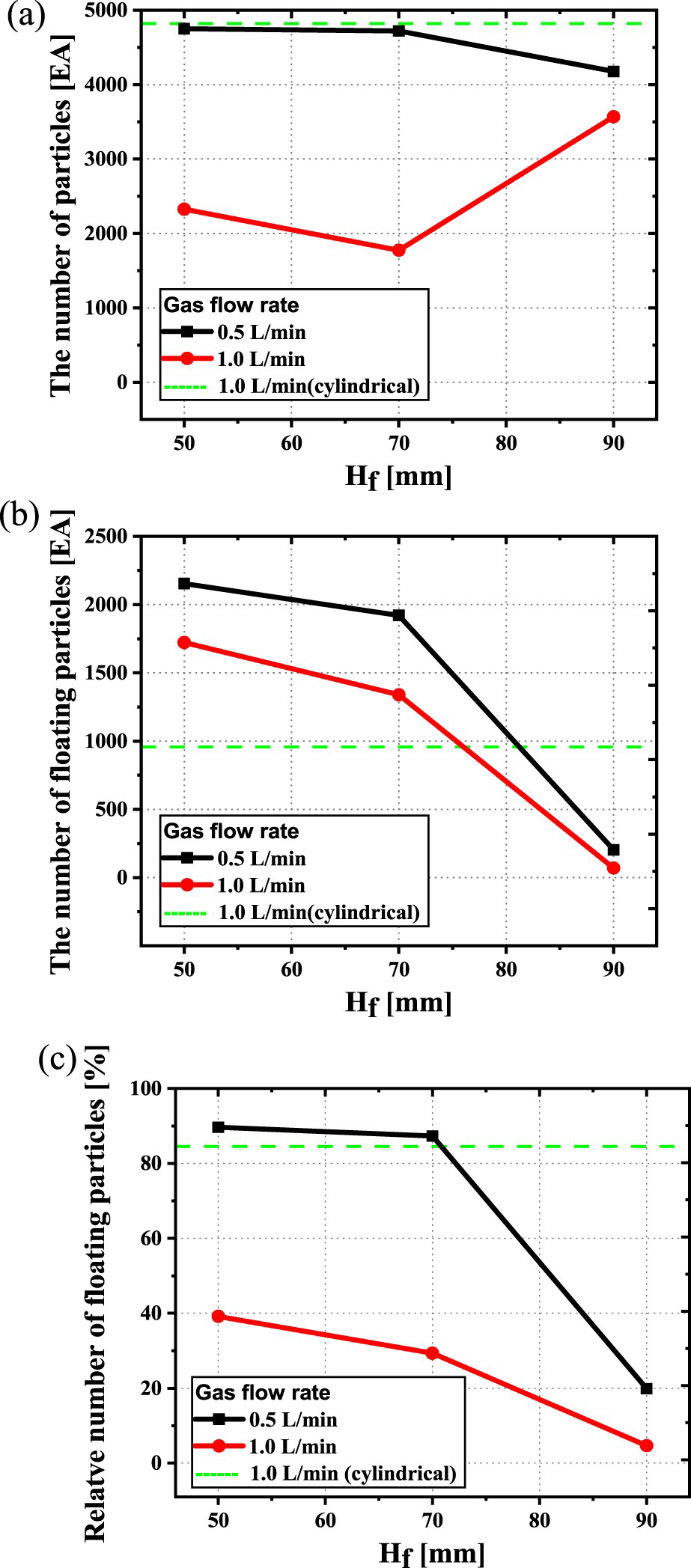
Floating particles were counted, except for particles discharged from the system or adsorbed on the top plane and the side wall, as plotted in Figure 12(b). The number of floating particles decreased with Hf and the gas flow rate. It is noteworthy that the number of floating particles in the cylindrical protective system was relatively small because approximately 80% of the particles were adsorbed on the boundary. Only 15% of the floating particles were discharged in the cylindrical protective system (Figure 12(c)). The ratio of floating particles to the total active particles, including the discharged particles, showed a similar tendency based on the gas flow rate and Hf.
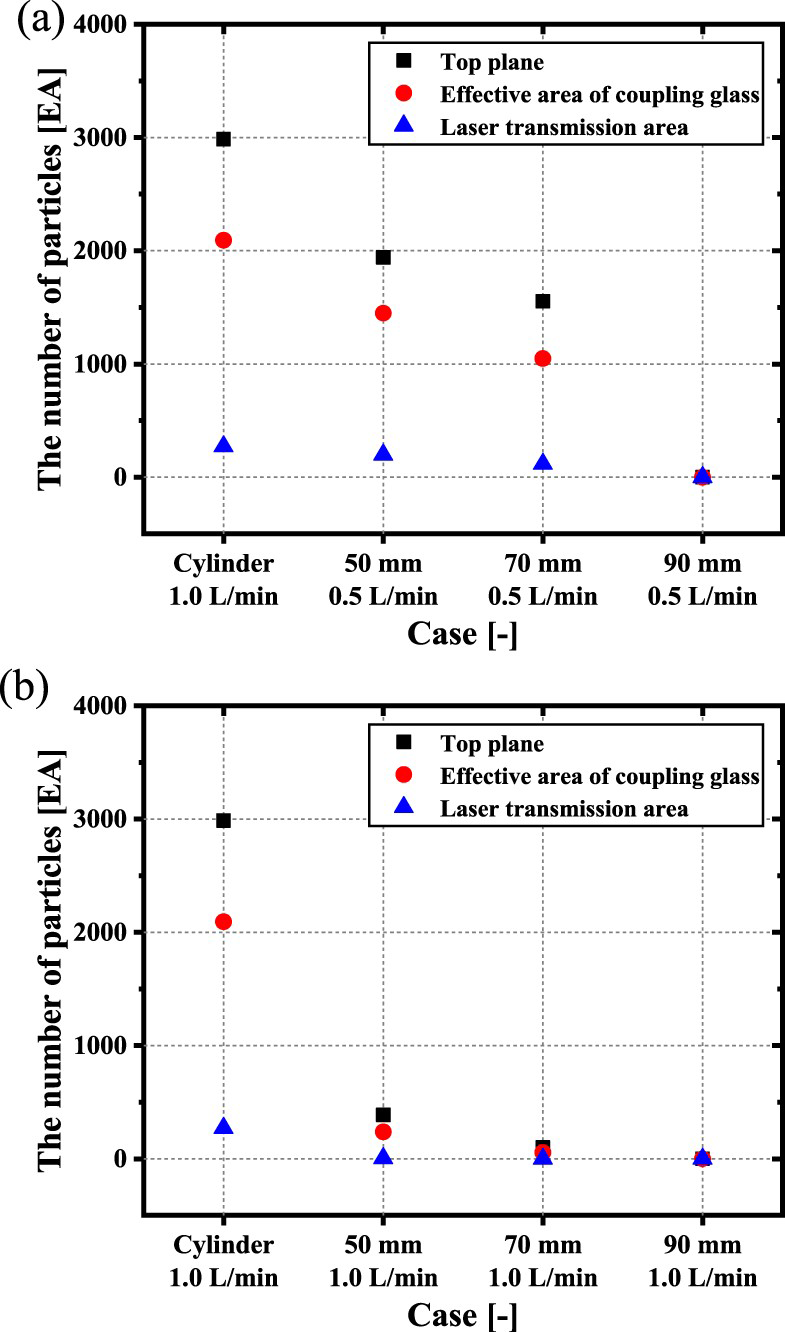
The particles adsorbed on the top plane for each condition are shown in Figure 13. The green circle denotes the effective area of the coupling glass, and the red circle denotes the laser transmission region. As summarised in Figure 14, a shielding gas flow rate of 1.0 L min−1 was able to suppress the fume adsorption compared with the case with a gas flow rate of 0.5 L min−1. At a gas flow rate of 0.5 L min−1, the particle absorption decreased linearly with Hf. By contrast, at a gas flow rate of 1.0 L min−1, only 0.1% of the generated particles were adsorbed on the laser transmission area for a Hf of 50 mm, and no particles were adsorbed for a Hf of 70 and 90 mm. When Hf was 90 mm, the particles could not ascend in the protective system, and no absorption was observed regardless of the gas flow rate. The shielding gas supplied along the X-axis (Y = 0) and the particle absorption along the X-axis was less than those along the other horizontal lines (Figure 13).
Distribution of adsorbed particles in the PTOP: Gas flow rates of (a) 0.5 L min−1 and (b) 1.0 L min−1. Number of adsorbed particles in each area of top plane: Gas flow rates of (a) 0.5 L min−1 and (b) 1.0 L min−1.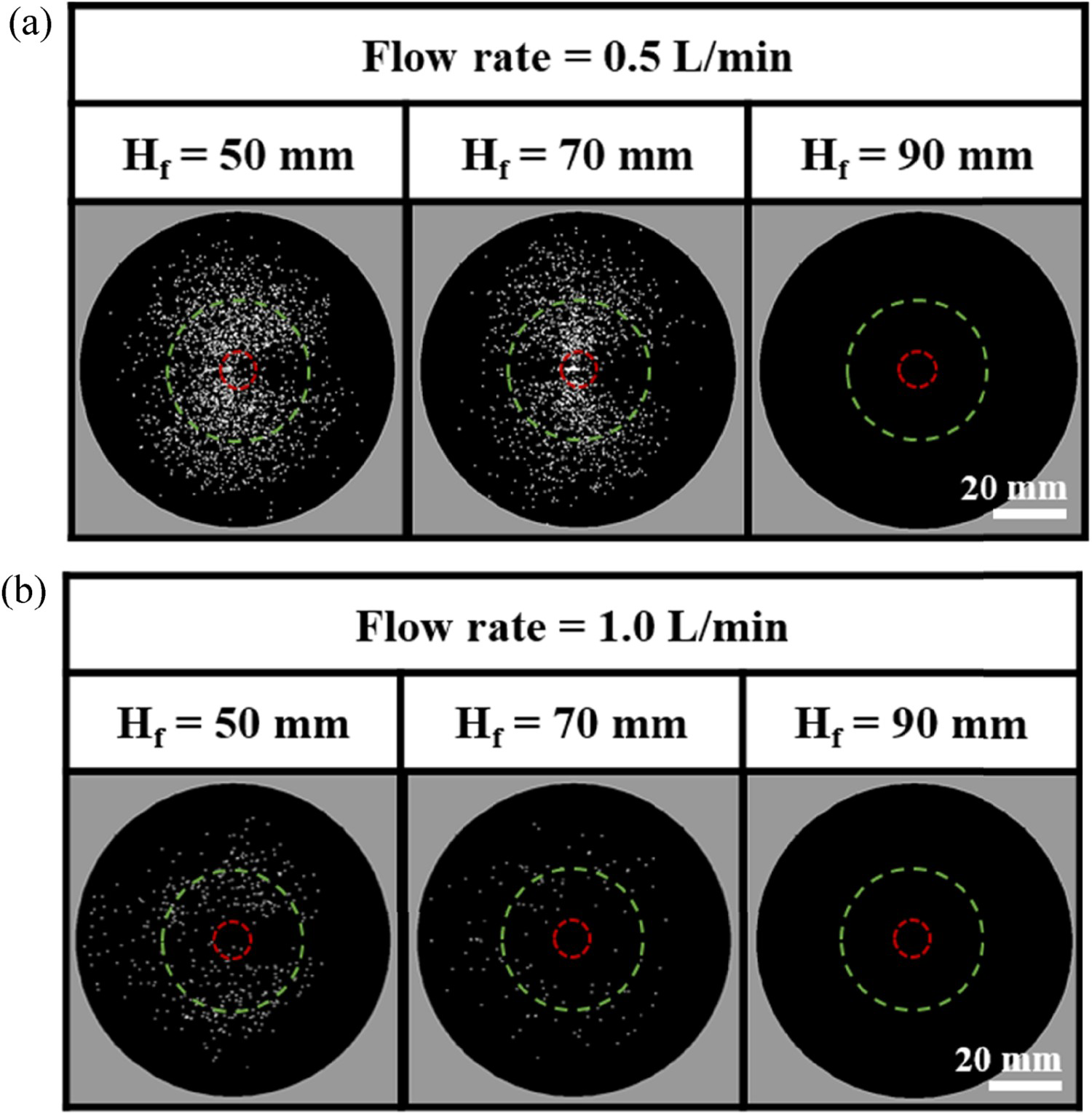
The coupling glass was imaged after a welding trial (Figure 15(a)), and compared with the simulation results (Figure 13) The contamination of the coupling glass exhibited a similar tendency to the adsorption behaviour in the simulation. The contamination index within the laser transmission area was calculated and compared with the simulations shown in Figure 15(b). The number of adsorbed particles on the laser transmission area coincided well with the measured contamination index in the same area. Because the transmittance of an unused coupling glass is not 100%, slight calibration may be necessary for achieving better correlation between the simulation and experimental results. However, the simulation model successfully predicted the experimental results qualitatively and quantitatively.
Comparison between numerical analysis and experimental results: (a) Photographs of coupling glasses after welding trial; (b) particle adsorption and glass contamination.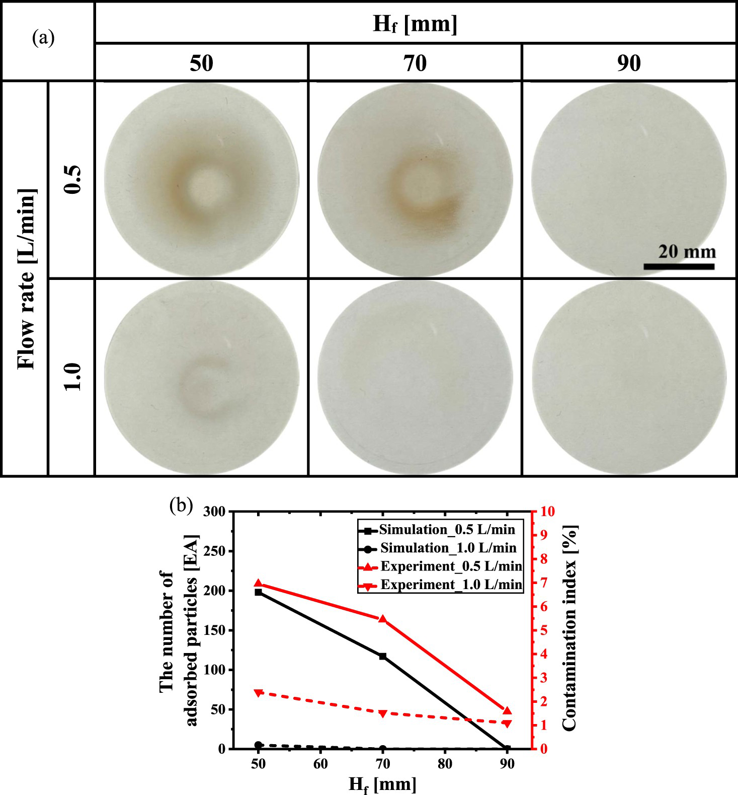
Conclusion
In this study, a conical protective system was proposed to suppress contamination on the coupling glass. The simulation was conducted based on the gas flow rate and the height of the conical bottom component of the protective system (Hf). The driving forces and mechanisms for suppressing contamination were discussed. The conclusions of this study are as follows:
The conical protective system provided excellent suppression of contamination on the coupling glass. When the flow rate was 1.0 L min−1, contamination on the laser transmission area was almost prevented at a Hf of 50 mm, and no contamination was observed at greater Hf. At 0.5 L min−1 of gas flow rate, the contamination reduced linearly as Hf increased, whereas it ceased at a Hf of 90 mm. Using a conical protective system, a dense streamline and stable descending flow was established near the aperture, which prevented the particles from ascending upward and facilitated particle discharge through the aperture. The particle ascending velocity, horizontal deflection of particles and number of residual particles in the system were identified as primary mechanisms for suppressing contamination by fume particles. The visual inspection of the coupling glass after the experiments coincided well with the particles adsorbed on the top plane in the simulation. The contamination index based on the coupling glass transmittance indicated excellent agreement with the simulated number of adsorbed particles.
Footnotes
Acknowledgement
We would like to acknowledge the technical & financial support from the KITECH (Korea Institute of Industrial Technology) of Republic of Korea (Grant EH-22-060).
Disclosure statement
No potential conflict of interest was reported by the author(s).