
Abstract
The heat un-balance and the immiscibility of the Cu and Fe alloy system are the key challenges during Cu/Fe resistance spot welding. Utilising electrodes of different geometries enabled the formation of a mixed Cu–Fe fusion zone. It is identified that despite the immiscibility of Cu and Fe in the solid-state, metastable liquid phase separation enables a metallurgical joining between Cu and Fe. The liquid phase spinodal decomposition led to the formation of an ultra-fine interconnected network of Cu-rich and Fe-rich phases in the fusion zone. The higher hardness of the fusion zone compared to the base metals, the susceptibility to solidification cracking, and the electrode indentation in the Cu sheet govern the mechanical properties of the Cu/Fe resistance spot welds.
Keywords
Introduction
The dissimilar joining of copper to steel enables combining the high thermal and electrical conductivity of Cu with the high strength and low price of the steel. Therefore, producing a sound and reliable dissimilar metallurgical Cu/Fe joint is essential for heat and electrical exchanger applications [1]. Moreover, the Cu/Fe joint is a critical challenge for manufacturing lithium-ion batteries. Welding the copper battery tab to the steel battery casing is crucial for reliable battery manufacturing [2]. However, the dissimilar metallurgical joining of Cu and Fe is challenging due to several factors, as summarised below:
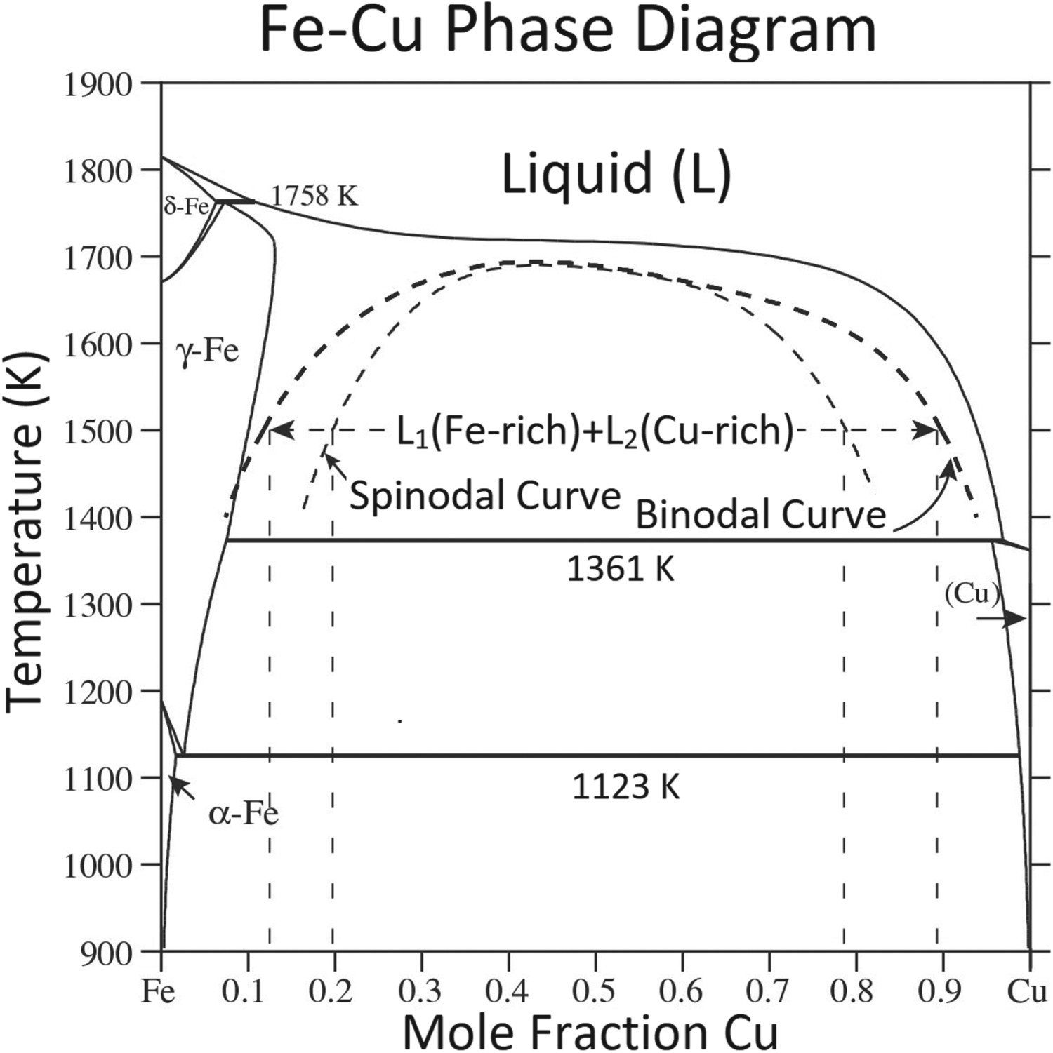
Large mismatch in physical properties: The significant difference between the melting point of the Fe and Cu (1538 vs. 1085°C) can lead to macro-segregation in the un-mixed zone of the fusion zone [1], in addition to melting challenges. The high thermal conductivity of the Cu (i.e. 398 W mK−1 [3]) compared to that of Fe (i.e. 80 W mK−1 [3]) affects its melting behaviour. The thermal expansion coefficient (CTE) mismatch between Fe and Cu (11.8 µm m−1·K−1 for Fe vs. 17 µm m−1·K−1 for Cu [3]) generates thermal stress during welding. The immiscibility of the Fe–Cu alloy system in the solid state: According to the Fe–Cu binary phase diagram [4] (see Figure 1), the mutual solid solubility of Fe and Cu is minimal. Moreover, there is no intermetallic compound in this alloy system. Therefore, producing a metallurgical joining between Fe and Cu is challenging. The metastable liquid-phase immiscibility: It is well established that the Fe–Cu system under non-equilibrium solidification conditions with large undercooling exhibited a metastable liquid miscibility gap [5–7]. This means that below a critical temperature, which is below the liquidus of the Fe–Cu system, the homogenous single-phase liquid is decomposed into two compositionally different liquids (L → L1(Fe–rich) + L2(Cu–rich)). Therefore, the sufficiently under-cooled Fe–Cu liquid experiences metastable liquid phase separation (MLPS). The formation of such metastable liquid–liquid phase separation in the Fe–Cu system has been related to the large positive deviations from Raoultian behaviour, positive heat of mixing, and atomic size mismatch in the Fe–Cu system [8]. The MLPS phenomenon affects the microstructure of the Fe–Cu alloys. Large solidification range: According to the Fe–Cu phase diagram and considering the positive segregation of Cu in the Fe during solidification, all Fe–Cu alloys exhibit an extensive solidification range. This factor, coupled with thermal stress induced by CTE mismatch, may cause solidification cracking during welding [9,10]. Cu-induced liquid metal embrittlement: It is shown that the molten Cu can easily penetrate the austenite grain boundaries and result in subsequent cracking/embrittlement if sufficient restraint (i.e. thick base metal, strong fixturing, etc.) is present [11]. The HAZ of C-Mn steel is susceptible to copper contamination cracking [12]. Fe–Cu binary phase diagram [4]: the phase diagram featured two peritectic reactions on both Fe-rich and Cu-rich sides, one eutectoid reaction, and a metastable liquid-phase miscibility gap as evidenced by a nearly flat liquidus curve. The binodal and spinodal curves are indicated in the phase diagram.
The metallurgical joining of Fe and Cu can be achieved via three distinguish mechanisms:
Metallurgical joining via formation of a liquid/solid interface between Fe/Cu (i.e. brazing mechanism) [13]. Metallurgical joining via formation of a solid/solid interface between Fe/Cu (i.e. solid-state welding mechanism), for example, diffusion welding [14]. friction welding [15], friction stir welding [16,17] and explosive welding [18]. Metallurgical joining via formation of a liquid/liquid interface between Fe/Cu (i.e. fusion welding mechanism), for example, arc welding [6,19], laser welding [20], electron beam welding [21].
Due to its simplicity, low cost, and high speed, resistance spot welding is an efficient, accessible, high-speed, and efficient joining process [22]. However, the application of RSW for the joining of very dissimilar metals (e.g. Al/Fe [23], Al/Cu [24], and Fe/Cu) is challenging. Due to the very low electrical resistivity of pure copper, less heat is generated in the Cu sheet. Moreover, the high thermal conductivity of Cu leads to very rapid heat dissipation. Therefore, heat balance during RSW of the Cu/Fe combination is challenging. The successful application of RSW for Cu/Fe dissimilar joining requires a thorough understanding of the joining mechanism and microstructure evolution during the joining process. This is the aim of this paper. First, the heat balance problem during Cu/Fe RSW is investigated. Then, the role of liquid phase separation on the formation of a metallurgical bond in an immiscible Cu/Fe alloy system and weld microstructure development is investigated. Finally, the mechanical properties of the welds are assessed during both the tensile-shear and the cross-tension tests.
Materials and methods
This work concerns the resistance spot welding of a drawing quality special killed (DQSK) low carbon steel (Fe–0.04 wt-% C–0.007 wt-% Si–0.25 wt-% Mn) and commercially pure copper (99.98 wt-% Cu) with 1 mm thickness. RSW was performed using a PLC-controlled, 120 kVA/50 Hz AC pedestal-type machine. Two different welding strategies were used for the joining of Cu/Fe, as follows:
Welding using a similar electrode at both sides: 45-deg truncated cone Resistance Welding Manufacturing Alliance (RWMA) Class 2 electrodes with 6-mm face diameters were used. Welding using different electrode geometry on both sides: Electrodes on the Fe and Cu sides were 45-deg truncated cone RWMA Class 2 electrodes with 8- and 4-mm face diameters.
In both welding strategies, electrode force, squeeze time, welding time, and electrode holding time after current-off were constant at 1.2 kN, 0.8 s, 0.2 s, and 0.2 s, respectively. The weldability current range was determined. The welding was performed under force control. It is of note that due to the problem associated with the electrode wear, the electrode tips were dressed frequently during welding trials. The welded samples were sectioned, sandpapered, and polished. First, the steel was etched with nital 2%, then copper was etched with 5 mL of NH4OH and 1 mL of H2O2 (30%) solution. The microstructural observations were performed using GX51 Olympus optical microscopy (OM) and TESCAN MIRA3 field-emission scanning electron microscopy (FESEM), operating at 15 kV. Energy Dispersive X-ray Spectrometer (EDS) was used for semi-quantitative chemical analyses of the phases present in the microstructure.
Mechanical properties of the joint were determined using the tensile-shear and the cross-tension test. The sample dimension for the tensile-shear and the cross-tension tests were 105 mm × 45 mm and 150 mm × 50 mm, respectively. The overlapped area for the tensile-shear and the cross-tension tests were 45 mm × 35 mm and 50 mm × 50 mm, respectively. The crosshead speed during mechanical testing was 5 mm min−1. The peak load and failure energy up to the peak load in the force-displacement curve were determined. Vickers micro-hardness test was performed using an applied load of 50 g and a duration of 15 s.
Results and discussion
Joining mechanisms
A successful metallurgical bond between two very dissimilar metals using RSW can be achieved using two distinct joining mechanisms: (i) fusion welding mechanism, which requires melting of both materials, and (ii) brazing mechanism, which relies on the formation of a solid/liquid interface between the materials and requires the melting of one the materials. It is of note that producing a robust metallurgical bond using a solid-state mechanism is not possible using RSW due to the absence of large plastic deformation at the joint interface, a prerequisite for the formation of a strong solid-state weld.
Two welding strategies were used to join Cu/steel combinations using RSW: (i) joining using RSW with a similar electrode at both sides and (ii) joining using RSW with different electrode geometry on both sides. Figure 2 shows the microstructure of the Cu/steel dissimilar joint made using a welding current of 14 kA with similar electrodes on both steel and Cu sides. A large melted zone was formed within the steel sheet (Figure 2(a)), which exhibited columnar grains with a martensitic microstructure (Figure 2(b)). According to Figure 2(c), the copper sheet did not experience melting during joining. During resistance spot welding of dissimilar materials with similar thickness using the same electrodes on both sides, the maximum electrical resistance may not be at the sheet/sheet interface; instead, it may be within the sheet of higher electrical resistivity. The formation of a melted zone in the steel sheet is due to its higher resistivity. The absence of melting in the Cu sheet is due to its very low electrical resistivity, which leads to inadequate heat generation and high thermal conductivity, leading to rapid heat dissipation. The Cu/steel interface remains solid due to the intense thermal sink effect of the Cu. Therefore, a solid/solid interface is created between steel and Cu sheets in this condition. Thus, a weak solid-state joint is formed by welding using similar electrodes on steel and Cu sheets. The attempt to measure the mechanical strength of the resultant joint failed due to weakness.
Fe/Cu resistance spot welds are produced using two similar electrodes on both sides: (a) macrostructure, (b) martensitic microstructure of the weld nugget formed on the steel side, (c) microstructure of Cu/Fe interface indicating the absence of melting in Cu side.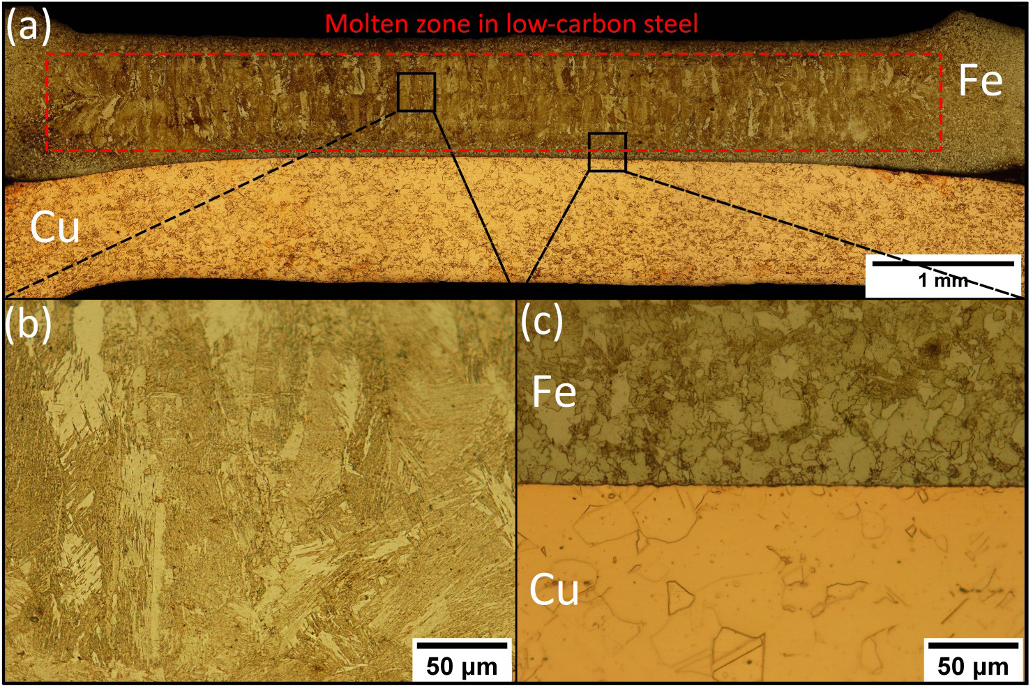
Producing a metallurgical Cu/steel joint with a brazing mechanism (i.e. liquid/solid interface formation between liquid steel and solid Cu) is challenging using conventional techniques. This is due to the intense heat sink effect of the Cu sheet, which precludes the melting of the steel sheet at the joint interface. Therefore, a successful metallurgical bond between Cu and steel using RSW can be achieved only by a fusion welding mechanism via enhancing the peak temperature experienced by the Cu sheet. The temperature of the Cu sheet during RSW of Cu/steel is controlled by several factors: Joule bulk heating of Cu sheet, heat transfer from steel sheet into the Cu sheet, and heat dissipation mechanisms. Therefore, in this work, the following approaches are attempted to increase the temperature in the Cu sheet:
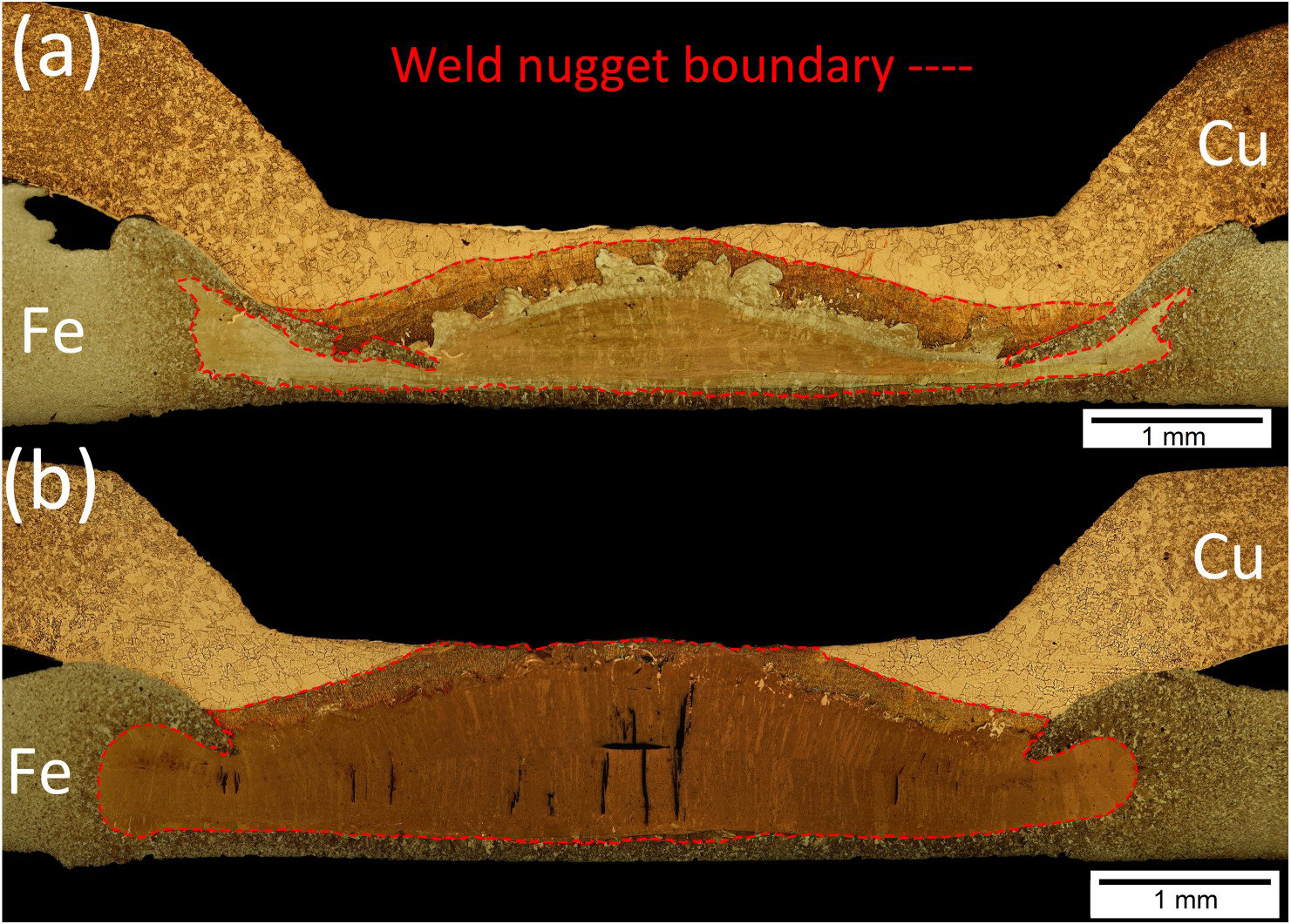
Using higher welding current: This approach which increases the bulk Joule heating of the Cu sheet is not practical due to the very low electrical resistivity of the Cu. The joining trials using welding current higher than 14 kA were not successful. At 15 kA welding current, the melted zone within steel extended to the entire sheet thickness and interacted with the tip of the electrode, and the electrode stuck to the steel sheet. Using different electrode geometry on both sides: The electrode geometry can affect power density and heat dissipation. Placing an electrode with a smaller tip diameter against Cu can increase the generated heat flux and reduce heat dissipation [25]. This strategy provided the heat balance in dissimilar Cu/steel joints during RSW utilising electrodes with different geometries. The electrode tip diameters of 4 and 8 mm were used on the copper and steel sides, respectively. Figure 3(a,b) shows the macrostructure of the Cu/steel joint made using a welding current of 13 and 14 kA, respectively. As can be seen, using different electrode geometries on Cu and steel sides, both Cu and steel sheets experienced melting during the joining thermal cycle. The melting of the Cu sheet is due to the increased heat intensity and the decreased heat dissipation. This welding strategy was successful in producing a strong Cu/steel bond. It is of note that the numerical simulation can provide more insight regarding the melting phenomena during Fe/Cu resistance spot welding. In the next section, the metallurgical features of the joint are discussed. Fe/Cu resistance spot welds produced using dissimilar electrodes on both sides: weld macrostructure at welding current of (a) 13 kA and (b) 14 kA.
Microstructural evolution mechanism
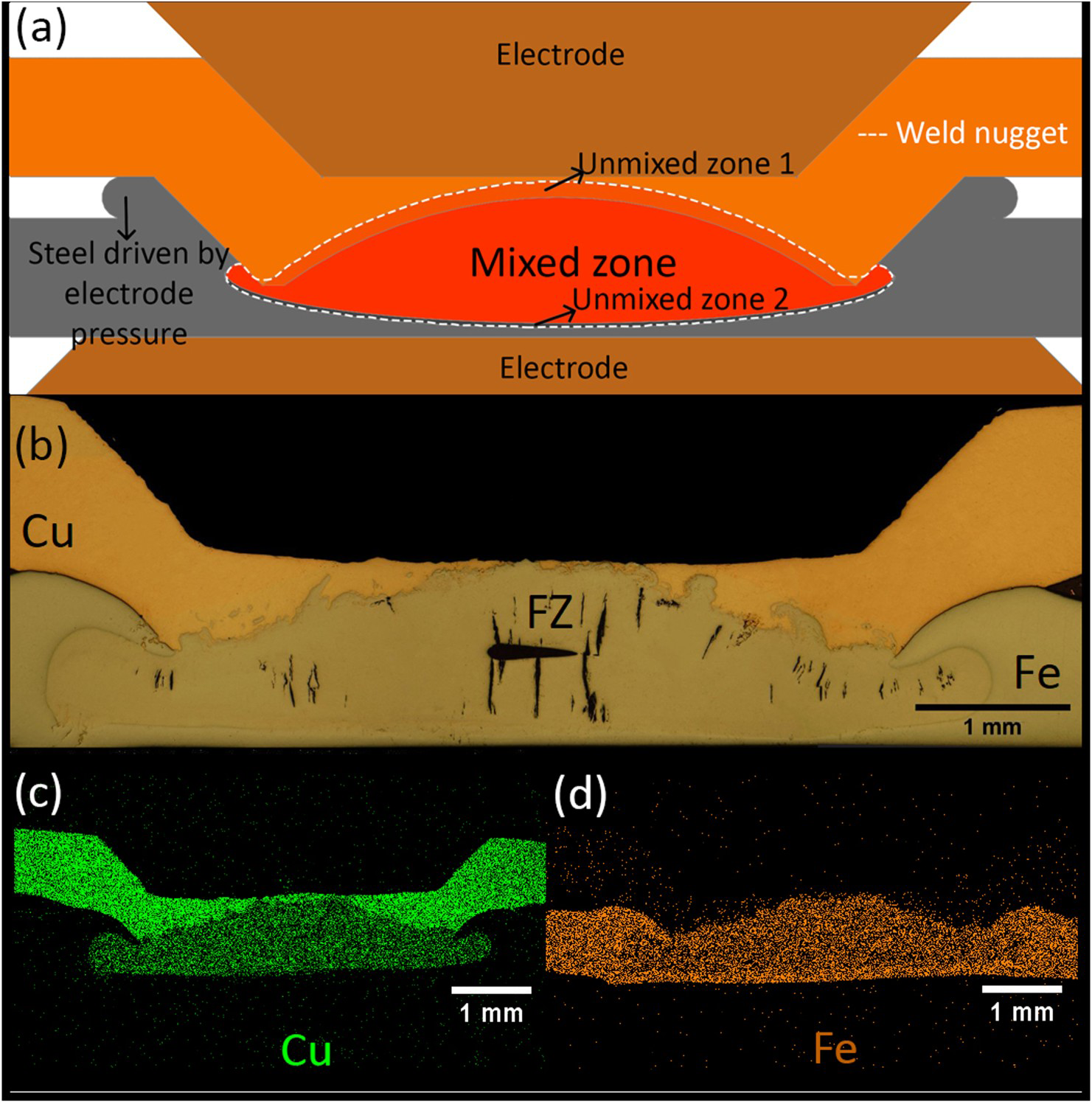
Figure 4(a) shows a schematic of a weld nugget formed between Cu and steel during RSW using electrodes with different geometry on both sides. The weld nugget consisted of a mixed bulk fusion zone narrow, a narrow unmixed zone adjacent to the Cu sheet, and a narrow unmixed zone adjacent to the steel sheet. The key microstructural features of the welds are discussed in the following:
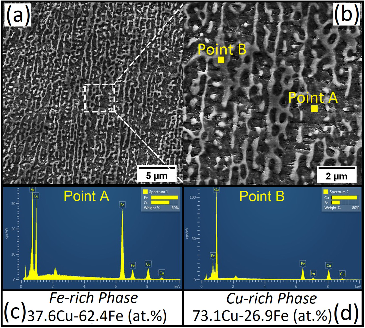
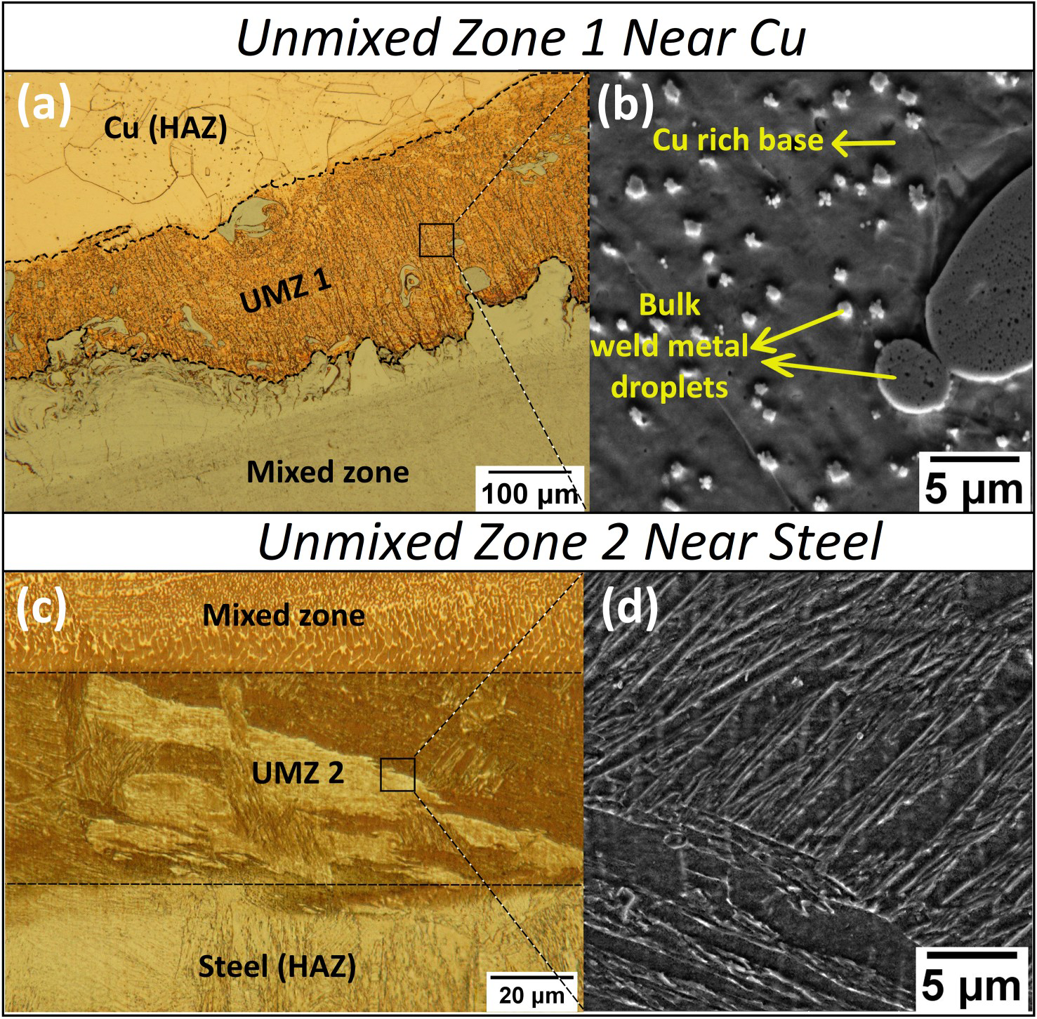
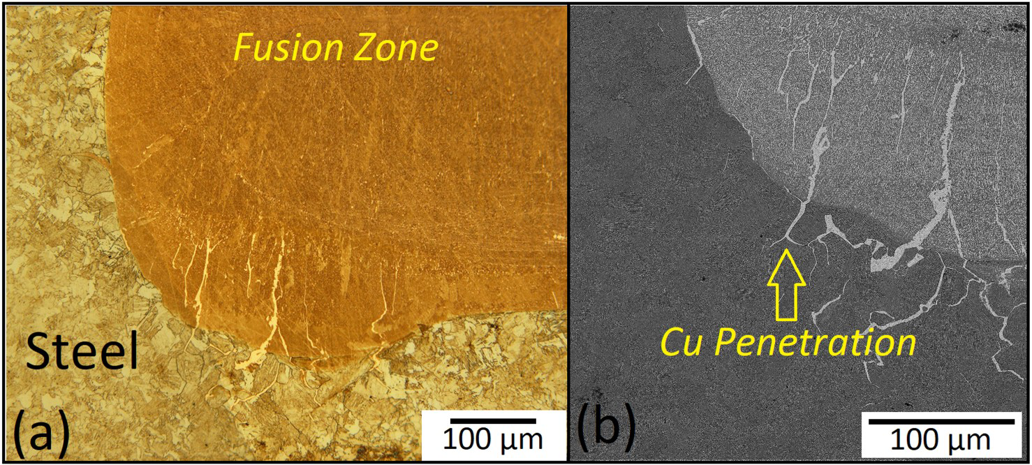
Microstructure of the mixed fusion zone: Figure 4(b) shows an un-etched weld macrostructure indicating the melted Cu sheet and melted steel sheets are fairly mixed in the mixed fusion zone, as indicated by the X-ray elemental map of Fe and Cu shown in Figure 4(c). The Cu content of the mixed fusion zone in welds made using 13 and 14 kA are 59.9 ± 5 and 57.0 ± 1.9 at.-%, respectively. Figure 5(a–b) shows the microstructure of the mixed zone in the weld nugget, indicating that two interconnected phases are formed in the mixed fusion zone. FESEM-EDS analysis (c–d) showed that the lighter phase is rich in copper (ca. 73.1 at.-% Cu–26.9 at.-% Cu), and the dark phase is rich in iron (37.6 at.-% Cu–62.4 at.-% Fe). The generated solidification microstructure can be understood with the help of the Fe–Cu binary phase diagram (Figure 1). First, suppose the solidification occurs under equilibrium conditions. Under equilibrium conditions, the solidification of the liquid nuggets begins with the formation of primary γ dendrites. The remaining Cu-rich liquid phase solidifies via a peritectic reaction. Therefore, the equilibrium constitution of the solidified nugget is pure Fe and Pure Cu. Therefore, in the equilibrium solidification condition, achieving a strong bond between Fe and Cu is not possible due to the immiscibility of Fe and Cu. However, as shown in Figure 5, the morphology and phase compositions in the mixed fusion zone are far from the equilibrium conditions. It is of note that easy-growth directions for dendritic growth for cubic crystals are <100>, which leads the secondary dendrite arms to grow perpendicular from the primary arm [26], which is not the case in the microstructure obtained in this work. Therefore, the mixed fusion zone microstructure does not exhibit dendritic morphology, indicating that the microstructure is not evolved from a single-phase liquid [26]. It is well established that the Fe–Cu system under non-equilibrium solidification conditions with large undercooling exhibited a metastable liquid miscibility gap (i.e. liquid phase separation occurs under rapid cooling) [5–8]. Under slow cooling rates, the evolution of heat of fusion compensates for the heat removal, and the melt freezes close to its equilibrium freezing point. For example, the experimental results of Munitz [27] showed that at cooling rates lower than 102 Ks−1, no liquid phase separation occurs in the Fe–Cu system, and the alloys solidify with dendritic microstructure. Under the rapid cooling condition, melt supercooling can be achieved. The required supercooling needed for LPS in Fe–Cu phase diagram depends on the alloy composition. According to Figure 1, for the central region of the Fe–Cu phase diagram, a small amount of supercooling is sufficient to promote the LPS phenomenon. The occurrence of LPS in Fe–Cu has been reported during electron beam melting [6], laser melting (for example [28]), and arc welding [19]. It has also been reported the presence of carbon atoms in Fe–Cu can also enhance the occurrence of LPS in this system [29]. During RSW, the Cu and Fe sheets melt and experience complete mixing in the mixed zone. During cooling, the liquid nugget experiences rapid cooling (i.e. high undercooling) due to the small volume of the liquid nugget and the intensive heat sink effect of the Cu sheet and electrodes. The rapid cooling during RSW provides the sufficient undercooling needed for LPS. When the mixed fusion zones are supercooled below a critical temperature, the liquid metal enters into a metastable liquid miscibility gap and separates into two liquids. As indicated in the Fe–Cu phase diagram (Figure 1), the MLPS can occur via the spinodal decomposition mechanism and the nucleation and growth mechanism, which depend on the liquid composition and the supercooling level. The compositions of the weld nuggets in both welding currents of 13 and 14 kA fall in the spinodal region. It has been reported that the liquid phase spinodal decomposition requires a higher cooling rate (i.e. higher supercooling) compared to the nucleation/growth mechanism [27,28,30]. The rapid cooling characteristics of RSW preclude liquid–liquid phase separation via nucleation/growth mechanism during the transition from the stable to the spinodal unstable region of the phase diagram. Therefore, LPS in the weld nugget occurs via liquid phase spinodal decomposition: the small composition fluctuations in the thermodynamically unstable liquid immediately produce narrow-sized Cu-rich and Fe-rich liquid phases. Under the high cooling rate, the solidification kinetics is expected to be sufficient to freeze the original morphology of the phase-separated melt. Therefore, the fusion zone rapidly solidified during RSW with interconnected morphology instead of the droplet-type structure, which is formed when the liquid–liquid phase separation occurs through the nucleation-growth mechanism [4]. The occurrence of liquid phase spinodal decomposition has been reported during laser surface alloying of Cu on steel substrate (Fe–Cu fusion zone with 30 wt-% Cu) [28] and cladding of Cu on steel using gas tungsten arc welding (Fe–Cu fusion zone with 35–55 wt-% Cu) [19]. The width of the spinodally decomposed phases during GTAW cladding of Cu on steel substrate was in the range of 1–5 µm [19]. The average width of the spinodally decomposed phases during laser cladding of Cu on steel substrate was reported to be 0.6 µm due to the higher cooling rate of laser melting compared to the arc melting [28]. In the present work, the width of phases was from 0.1 to 1 μm, indicating that the achieved cooling rate and hence undercooling is higher than laser melting and GTAW cladding. The cooling rates during RSW can be as high as 105 ks−1 [22]. This rapid cooling provides the sufficient undercooling needed for spinodal liquid phase separation in Fe–Cu system. It is of note that the solubility of Cu in the Fe-rich phase and Fe in the Cu-rich phase significantly exceeds to equilibrium maximum solubility in the Fe–Cu system due to the rapid cooling effects of RSW, as also reported by others [19,27,28]. Therefore, the occurrence of liquid phase separation in the Fe–Cu system, which produces metastable solid solution phases, is the key to producing the metallurgical bond between Fe and Cu, which are immiscible in equilibrium conditions. The hardness of the mixed zone in weld nugget made using 14 kA was 198 ± 19 HV, which is higher than the hardness values of the base metals, 105 ± 9 HV for the steel side, and 55 ± 5 HV for the Cu side. The higher hardness of the mixed fusion zone is due to its two interconnected phase structure and ultra-fine scale microstructure resulting from liquid phase spinodal decomposition. Solidification cracking in the fusion zone: According to Figure 3(b) and Figure 4(b), solidification cracks are formed in the through thickness direction of the weld nugget produced using a welding current of 14 kA, in addition to the shrinkage void, which is created at the nugget centre. Generally, a wide mushy zone, the crack susceptible semi-solid zone, and high tensile stresses induced by obstructed contraction of the solidified weld metal promote solidification cracking during welding [9,31]. The wide solidification temperature ranges of Fe–Cu alloys (e.g. about 330°C for Fe–57 at.-% Cu) and high heat input creates a wide mushy zone. It is of note that the solidification temperature range also becomes wider under non-equilibrium solidification conditions [31,32]. The solidification temperature range for welds made at 13 and 14 kA is nearly the same, as suggested by the Fe–Cu phase diagram. Therefore, the crack formation in welds made at 14 kA is due to its wider mushy zone induced by its higher welding heat input. Welding using a lower welding current, which decreases both the size of the mushy zone and the tensile stresses, eliminates the solidification cracks. Formation of un-mixed zones: The un-mixed zones, visible as beaches and islands or peninsulas, are generally narrow bands that experience melting without mixing with the other component of the weld (i.e. other dissimilar base metal or dissimilar filler metal) and then re-solidified [1,9]. These essentially melted-and-solidified base metals are formed at the fusion boundary in heterogeneous welds due to the lack of sufficient liquid flow in the fusion boundary. Figure 6(a) shows the cellular microstructure of the Cu-rich (i.e. more than 92 at.-% Cu) beach-like unmixed zone beside the copper base metal along with islands with a chemical composition similar to the mixed weld metal. The hardness of this zone was 40 HV. Figure 6(b) shows the microstructure of the narrow beach-like un-mixed zone beside the steel base metal. This region is iron-rich with a low percentage of copper (i.e. about 14 at.-% Cu). The martensitic microstructure of this zone is evident. Liquid Cu infiltration along the steel grain boundaries: Figure 7 shows the liquid Cu infiltration between the grain boundaries of the steel. The intergranular penetration of the low-melting-temperature Cu liquid along the steel grain boundaries relies on the ability of liquid Cu to wet the steel grain boundaries. It is well documented that the liquid Cu can effectively wet the austenite GB [11,12]. This explains the Cu penetration along the GBs of the steel upper-critical heat-affected zone, which experiences austenitization during welding. However, the cracking due to liquid metal embrittlement (LME) did not occur due to insufficient tensile stress to induce cracking. Fe/Cu resistance spot welds produced using dissimilar electrodes at both sides using a welding current of 14 kA: (a) schematic of weld macrostructure showing the presence of a completely mixed zone in the fusion zone and two un-mixed zones, (b) weld macrostructure without etching, (c) low magnification X-ray elemental map for Cu and Fe. (a–b) Fusion zone microstructure made using a welding current of 14 kA showing an interconnected two-phase fine microstructure, (c–d) EDS-FESEM based chemical analysis of two phases formed in the fusion zone. Unmixed zone formation in Cu/Fe resistance spot weld: (a–b) unmixed zone near the Cu and (c–d) unmixed zone near the steel. (a) LOM and (b) FESEM micrographs showing the liquid Cu penetration along the steel grain boundaries.
Mechanical properties
Figure 8(a–b) shows the failure mode and mechanical properties of Cu/steel joints produced using different electrode geometries on both sides at currents of 13 and 14 kA during the tensile-shear (TS) test. Figure 8(c–d) shows the failure mode and mechanical properties of Cu/steel joints during the cross-tension (CT) test. The size of the fusion zone along the sheet/sheet interface (FZ size), the electrode indentation depth, the weld defects (void and cracks), and the weld hardness characteristics are the key factors governing the mechanical properties of the spot welds [22]. No interfacial failure was observed during mechanical testing of the welds due to (i) sufficient FZ size to support the imposed stresses and (ii) higher hardness of the FZ compared to the base metals, which prevents the occurrence of the failure completely through the FZ. The failure initiated from the Cu side is due to the large electrode indentation in this sheet and its lower hardness compared to the steel sheet. The size of the FZ along the sheet/sheet interface, which contributed to the load-bearing capacity of the joints in welds made at 13 and 14 kA is 3.5 and 4.7 mm, respectively. Despite the fact that the FZ size of the welds made at 14 kA is 30% higher than that of 13 kA, however, peak load and energy absorption of the welds are enhanced by less than 10%. This can be attributed to the presence of voids and cracks within the FZ of welds made at 14 kA, which reduces the effective load-bearing area of the welds. The effect of cracks on the weld mechanical properties in the CT test was more pronounced than in the TS test due to the different loading conditions of these two test types. While during the TS test, the tensile stress acting on the base sheet is the driving force for pullout failure, during the CT test, the shear stress along the through thickness direction is the driving force of the pullout mode [22]. The presence of through thickness solidification cracks in the FZ of the welds made at 14 kA provides an easy crack-growth path during the CT test, which leads to a change in failure mode from pullout to partial pullout, which in turn reduces the weld peak load and energy absorption at higher welding current.
Mechanical properties of Cu/Fe resistance spot welds during the tensile-shear and cross-tension tests: (a–b) failure modes and peak load and energy absorption during TS test and (c–d) failure mode and peak load and energy absorption during CS test.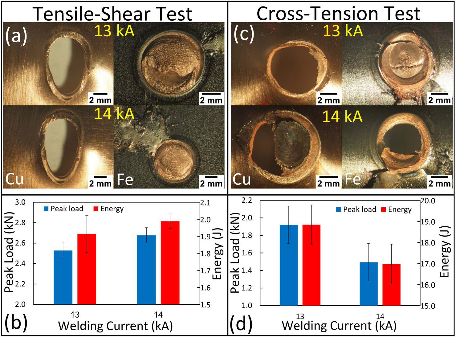
Conclusions
The joining challenges of immiscible Cu and Fe using resistance spot welding are addressed. The first challenge is the unbalanced heating of the Fe and Cu sides, which prevents the formation of a strong metallurgical bond, which can be solved using two different electrode geometry on the Cu and Fe sides. This approach was successful in melting both Cu and Fe sheets. The second key challenge is the immiscibility of Fe and Cu in solid-state, which prevents the metallurgical bonding of Cu and Fe. However, due to the thermodynamic tendency of Fe–Cu liquid towards liquid immiscibility and the non-equilibrium solidification condition and large undercooling during RSW, the liquid phase separation occurs via spinodal decomposition. Due to spinodal metastable liquid phase separation, an ultra-fine interconnected microstructure of a Fe-containing Cu-rich phase and a Cu-containing Fe-rich phase is formed, improving the metallurgical bonding of Cu and Fe. The formation of solidification cracks perpendicular to the sheet/sheet interface originated from a large solidification temperature range, and severe electrode indentation on the pure Cu side are the key factors limiting the achievable load-bearing capacity of Cu/Fe resistance spot welds. Finally, it is of note that electrode wear on the Cu side was evident in this work which can affect the reproducibility of the welding process. The problems associated with electrode wear and large electrode indentation can be solved using a steel cover plate on the Cu sheet.
Footnotes
Disclosure statement
No potential conflict of interest was reported by the author(s).