
Abstract
The bimetallic structure formed by TC4 and Inconel718 has broad potential applications in aerospace. Based on the laser deposition manufacturing technique, a TC4/Inconel718 bimetallic structure was fabricated via the Ta/Cu transition layer. The test results indicated that a Ta/Cu transition region with a width of 475.0 μm was formed. The microstructure of the transition region changed from a reticular to a rod structure, and the corresponding phase compositions were β-Ta + Ti2Cu + TiCu and TiCu+γ-Cu + Cr2Ta. Owing to the formation of Ti–Cu and Cr–Ta phases in the transition region, the Vickers hardness reached 444.0 HV. The ultimate tensile strength was 280 MPa, and the fracture morphology presented a quasi-cleavage fracture, which occurred in the Ta/Cu transition region where Ti–Cu brittle phases exist.
Keywords
Introduction
Compared with traditional manufacturing technologies such as brazing and diffusion welding, the laser deposition manufacturing (LDM) technique has the characteristics of high production efficiency, high bonding strength, and low surface requirements, which are unique advantages for the manufacturing of bimetallic structural parts [1,2]. The bimetallic structure can make full use of the excellent properties of the two materials and has broad potential applications in the aerospace, biomedicine, oil & gas, power generation, and nuclear industry. It can meet the needs in these fields, such as high-performance, lightweight, high thermal/electrical conductivity, high wear resistance and corrosion, and multifunctional parts [3–6].
According to the compatibility between different materials, bimetallic structures can roughly be divided into two categories by the raw material composition. One is the bimetallic structure composed of similar metals with similar chemical composition and physical properties. Wang et al. [7] and Bryan et al. [8] showed that TA15/TC11 and SS316/SS430 bimetallic structures with no defects and excellent bonding quality can be obtained by direct bonding or gradient transition without interlayers. On the other hand, due to the difference in metallurgical and thermal physics properties between two metals with poor compatibility, it is difficult to obtain a high bonding strength and defects such as cracking and delamination can even be produced [9]. The bimetallic structure formed by titanium with a high strength-to-weight ratio and nickel-based alloy with excellent high-temperature properties is a typical representative of this structure. According to the research, Ti2Ni, Ni3Ti, and Ni3Ti2 brittle intermetallic compounds (IMCs) will be formed in the bonding region of a directly bonded [10,11] or gradient transitioned [12] titanium alloy and nickel-based alloy. The IMCs will seriously affect the mechanical properties of the titanium/nickel-based alloy bimetallic structure.
The current solution is to select a suitable material as a transition interlayer between titanium and the nickel-based alloy to inhibit the formation of Ti–Ni brittle IMCs. Thiriet et al. [13] and Oliveira et al. [14] used a Mo gradient transition layer and a pure Nb intermediate layer as a transition layer between titanium and nickel-based alloy. The formation of Ti–Ni IMCs was inhibited successfully. In order to limit the formation of brittle phases, the Nb/Cu composite transition layer [15] and Ta/Cu composite transition layer [16] were selected with the same thickness (about 2.0 mm) by LDM. The results showed that the Ti–Ni brittle phase was inhibited and the bimetallic structure without metallurgical defects was obtained. The tensile strength of the Ta/Cu transition layer [16] was higher (about 369 MPa) compared to the Nb/Cu transition layer [15]. Therefore, Ta/Cu is an ideal material for the transition layer of the titanium and nickel-based alloy bimetallic structure. However, Ta has a density of about 16.6 g cm–3 [17], which is much higher than TC4 [18] (density is about 4.5 g cm–3). In addition, the low melting point of Cu (1083.4°C) leads to a poor high-temperature strength [19]. Therefore, the thickness of the Ta/Cu transition layer is too large, which would limit the lightweight and high-temperature performance of the bimetallic structure. However, the LDM technique can easily reduce the thickness of the Ta/Cu transition region by reducing the number of deposited layers, which provides technical support for fabricating bimetallic structures with a thinner transition layer.
Based on the LDM technology, the titanium alloy TC4 and nickel-based alloy Inconel718, widely used in aerospace, were used as raw materials. The TC4/Inconel718 bimetallic structure with a thinner Ta/Cu composite interlayer (about 1.0 mm) as the transition layer was fabricated. In the current study, the microstructure, element distribution, phase composition, Vickers hardness distribution, and room temperature tensile strength of the bimetallic structure were investigated in detail.
Materials and methods
A commercial hot rolled TC4 titanium alloy sheet was selected as the substrate, and the dimensions of the substrate were 100 × 200 × 20 mm (length × width ×height). Before the LDM experiment, the substrate surface was polished by a rotary file and cleaned in acetone, and then it was vacuum dried at 200°C for 1 h. Powder materials for the bimetallic structure were TC4, Ta, Cu, and Inconel718 powders fabricated by PREP (plasma rotating electrode process). The size of TC4 and Inconel718 powder ranged from 100 μm to 150 μm. The chemical composition of the Inconel718 powders is 50.0∼55.0Ni, 17.0∼21.0Cr, 4.8∼5.5Nb, 2.8∼3.3Mo, 0.7∼1.1Ti, and the balance is Fe. The chemical composition of the TC4 powders is 5.5∼6.8Al, 3.5∼4.5 V, 0.1∼0.25Fe, 0.2O, and the balance is Ti. The particle diameter of Ta and Cu powders ranged from 50 μm to 100 μm, and the purity is about 99.90%. These powders of TC4, Ta, Cu, and Inconel718 were vacuum dried at 120°C for 2 h to remove moisture before the experiment.
The LDM experiment was carried out in an LDM2500 laser additive manufacturing system, and the maximum component manufacturing dimension was 2500 mm × 2500 mm × 1500 mm. The system includes a 10,000 W fibre laser, a laser deposition head, a 3-axis mechanical working table, an argon-purged chamber, a CNC system, and a coaxial powder delivery system. The argon-purged chamber kept the oxygen level below 50 ppm during LDM.
During the LDM experiment, the laser deposition head output laser is used as the heat source to melt the synchronously delivered metal powder, and the TC4, Ta, Cu, and Inconel 718 are manufactured by laser deposition in turn. The TC4/Inconel718 bimetallic structure sample of 35 × 20 × 40 mm was fabricated. The main LDM processing parameters were selected, TC4: 1700 W laser power, 420 mm min–1 scanning speed, 6.0 g min–1 powder delivery rate, 3.8 mm focal diameter, and 0.5 mm layer thickness; Ta: 2300 W laser power, 420 mm min–1 scanning speed, 7.2 g min–1 powder delivery rate, 4.2 mm focal diameter, and 0.5 mm layer thickness; Cu: 1300 W laser power, 420 mm min–1 scanning speed, 6.5 g min–1 powder delivery rate, 3.2 mm focal diameter, and 0.5 mm layer thickness; Inconel718: 1500 W laser power, 420 mm min–1 scanning speed, 6.3 g min–1 powder delivery rate, 3.4 mm focal diameter, and 0.5 mm layer thickness. The scanning strategy and powder-feeding mode of the LDM are shown in Figure 1(a). In order to obtain a thinner Ta/Cu transition layer, the deposition number of the Ta interlayer and Cu interlayer is reduced. There was one layer each of Ta and Cu. The physical drawings and schematic diagrams of the bimetallic structure are shown in Figure 1(b and c).
(a) Schematic diagram of the LDM scanning strategy, (b) physical diagram of the TC4/Inconel718 bimetal structure, (c) schematic diagram of the TC4/Inconel718 bimetal structure.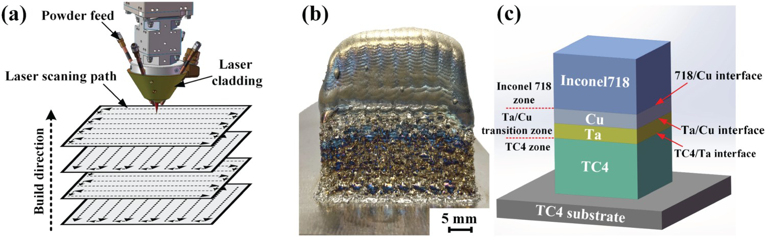
The metallographic and tensile specimens were prepared by an electrical discharge wire-cutting machine in a cross-section along the growth direction of LDM. The specimens for microstructure analysis were first polished with SiC sandpapers and then polished with an argon ion polishing equipment (ilion ii 697). A Gemini SEM300 scanning electron microscope with EDS (energy dispersive spectroscopy) characterised the microstructure and element evolution of the bimetallic structure. EBSD (electron backscatter diffraction) was utilised to characterise the phase composition and distribution of the micro-regions. The evolution of the phases from each interface was characterised using an XRD (X-ray diffraction, XRD-7000) diffractometer, and the range of diffraction angles (2θ) was selected as 30°∼90° at a scanning speed of 4° min–1. The tensile property of the TC4/Inconel718 bimetallic structure was tested on a universal testing machine (MTS-100) with a loading rate of 0.5 mm min–1. The SN3400 SEM was used to characterise the fracture morphology. The Vickers hardness of each region and interface was measured by a Vickers indenter (Wilson Hardness UH 250) with a load of 0.98 N and a dwell time of 10 s.
Results and discussion
In the current study, although the thickness of the Ta/Cu transition layer was reduced, the TC4/Inconel718 bimetallic structure without visible defects was still obtained, as shown in Figure 1(b). In order to express the regions and interfaces more clearly, the bimetallic structure was divided into three regions (TC4 region, Ta/Cu transition region, and Inconel718 region) and three interfaces (TC4/Ta interface, Ta/Cu interface, and Cu/Inconel718 interface), as shown in Figure 1(c). The microstructure of the three regions and three interfaces of the bimetallic structure is given in Figure 2(a). From the figure, it can be seen that the bimetallic structural parts have good forming quality without metallurgical defects. It can be seen from the EDS line scan results (Figure 2(b)) that the elemental diffusion occurs in each interface, indicating the formation of a good metallurgical bond.
Ta/Cu transition region of the bimetallic structure (a) microstructure and (b) EDS line scanning results of the yellow arrow in (a).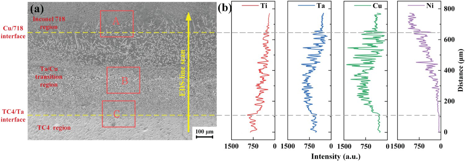
Microstructure of the bimetallic structure
As presented in Figure 2(a), the microstructure shows a complex morphological evolution with no cracks or pores formed from the TC4 region to the Inconel718 region. Located in the TC4 region is mainly a white planar crystal structure. It is mainly composed of the solid solutions of β-Ti and β-Ta. In the upper region, the microstructure of Inconel718 is mainly composed of columnar austenite and eutectic structures. From the TC4/Ta interface to the centre, the white planar crystal structures appear near the interface at first. Then, fine reticular and granular structures were gradually formed in the upper Ta/Cu transition region (Ta deposit layer). The Ta/Cu transition region (Cu deposit layer) is mainly composed of white equiaxed crystals and a grey-black interwoven microstructure. Through the Cu/Inconel718 interface, the white equiaxed crystals gradually disappear. It gradually develops into the Inconel718 microstructure (columnar austenite and eutectic structure).
The results of the elemental composition analysis of the EDS line scanning along the direction of the yellow arrow in Figure 2(a) for the three regions and the three interfaces are shown in Figure 2(b). It can be seen from the figure that along the arrow direction, the Ti content shows a decreasing trend, while the Ni content shows an increasing trend. Meanwhile, the contents of Ta and Cu first increased and then decreased. Because the Ta/Cu transition region is located in the middle of Figure 2(a), which mainly contains Ta and Cu, the content of Ta and Cu first increases and then decreases from the TC4 region to the Inconel 718 region, it is also consistent with the EDS line scan results in Figure 2(b). The results of the EDS line scanning indicate that the white planar crystal near the TC4/Ta interface mainly contains Ta and Ti elements. Because Ta and Ti have full solubility, it further shows that the white planar crystal is composed of the solid solution of β-Ti and β-Ta [20]. Because γ-Cu and γ-Ni have full solubility, the interface of Cu/Inconel718 is mainly composed of a γ-Ni and γ-Cu solid solution. Therefore, it can be speculated that the grey-black parts occupying a larger area at the Cu/Inconel 718 interface in Figure 2(a) are the solid solution of γ-Ni and γ-Cu. The white equiaxed crystals are the precipitated second phase. It can be seen from Figure 2(b) that both the Ta and Cu contents are high between the two dotted lines. It shows that the region between the two yellow dashed lines in Figure 2(a) is the Ta/Cu transition region in the bimetallic structure, with a width of about 475.0 μm. It is noteworthy that the Ta/Cu transition region has an obvious interface with the Inconel718 region above and the TC4 region below in terms of the element distribution and microstructure, respectively. However, as shown by the yellow dotted lines in Figure 2(a), the microstructure transition of the Ta/Cu transition region is relatively natural, and no obvious boundary was formed.
To further confirm the microstructure and elemental composition of the Ta/Cu transition region in the TC4/Inconel718 bimetallic structure, the magnified microstructure and corresponding EDS map scanning of the Ta/Cu transition region (red rectangular boxes A, B, and C in Figure 2(a)) are given in Figure 3(a–c).
Microstructure of the bimetallic structure: (a) the interface of the Ta/Cu transition region and Inconel718 region, (b) Ta/Cu transition region, and (c) the interface of the Ta/Cu transition region and the TC4 region.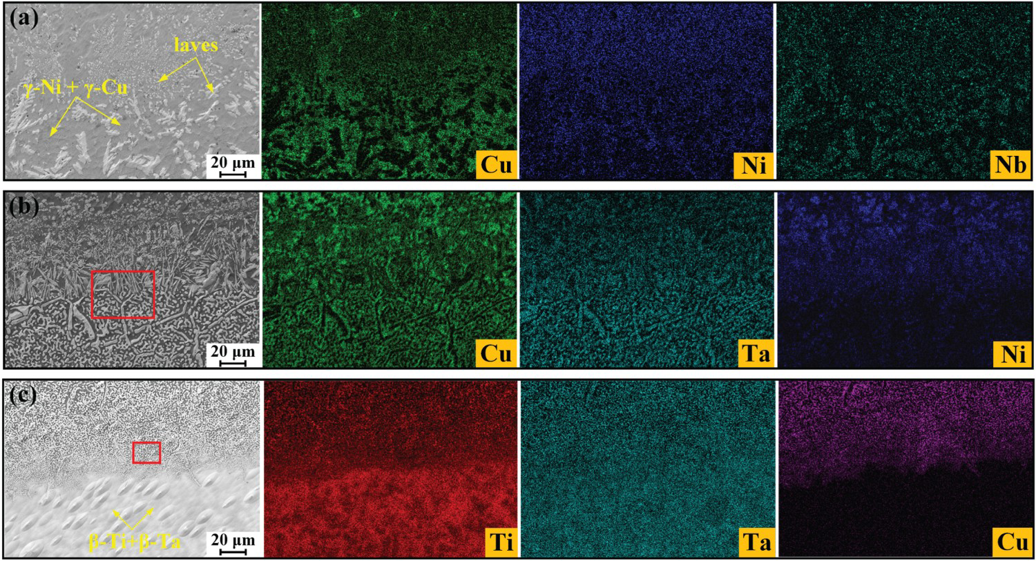
Figure 3(a) shows the microstructure and corresponding EDS maps near the Cu/Inconel718 interface. The microstructure in this region is mainly composed of a white equiaxed precipitated phase and a grey-black matrix between the white equiaxed structure. The diameter of the white equiaxed structure below the Cu/Inconel718 interface is about 8∼10 μm, while the diameter of the equiaxed structure above the Cu/Inconel718 interface is about 2.0 μm. According to the EDS maps of Figure 3(a), the grey-black microstructure near the Cu/Inconel718 interface mainly contains Cu and Ni. Along the interface from bottom to top, the Cu content decreases gradually while the Ni content increases gradually. Therefore, the grey-black microstructure is the solid solution of γ-Ni and γ-Cu. The EDS map scanning results in Figure 3(a) show that Nb is segregated in the white precipitated phase near the Cu/Inconel718 interface. According to the research [21], the white equiaxed precipitated phase is the laves phase (Fe2Nb, Cr2Nb) formed by Nb, Fe, and Cr in Inconel718.
The microstructure and the corresponding EDS maps at the Ta/Cu transition region are shown in Figure 3(b). As presented in the figures, under the Ta/Cu transition region, a reticular structure (the width of the white phase is about 3.75 μm) is formed by the interweaving of the white structure (Ta-rich) and the grey-black structure (Cu-rich). In the middle part of the Ta/Cu transition region, fine white stripe phases (rich in Ta and 1.43 μm in width) and grey-black phases (Cu-rich) are formed between the stripe phase. In the upper part of the Ta/Cu transition region, the white equiaxed crystals (Cr-rich) are formed and distributed in the grey-black matrix (rich in Ni and Cu). The results of the EDS maps show that the Ta content decreases and the Ni content increases, while the distribution of Cu is more uniform from bottom to top along the interface. It is inferred that the white (Ta-rich) phase under the Ta/Cu transition region is mainly composed of β-Ta. In addition, the grey-black structure (Cu-rich) is mainly composed of Ti–Cu IMCs. In the middle of the Ta/Cu transition region, the fine white striped phase (Ta-rich) is inferred to be an IMC formed by Ta and Cr (element in Inconel718), and the black structure (Cu-rich) is mainly composed of γ-Cu. The white equiaxed structure (Cr-rich) in the upper part of the Ta/Cu transition region is mainly composed of Ta–Cr IMCs, while the grey-black structure is composed of γ-Cu and γ-Ni.
The microstructure and the associated EDS maps of the Ta/TC4 interface are presented in Figure 3(c). It can be seen from the figures that there is a large amount of Ti under the Ta/TC4 interface. The microstructure in this region is mainly composed of a basket structure woven between needle-like α-Ti and α-Ti+β-Ti [17]. The microstructure above the Ta/TC4 interface is mainly composed of a fine white equiaxed structure (rich in Ta with a diameter of about 1.8 μm) and a grey-black structure (Cu-rich) distributed between the equiaxed structure. Along the interface from bottom to top, the Ti content decreases gradually, while the content of Ta and Cu increases gradually. Therefore, it can be inferred that the microstructure above the Ta/TC4 interface is mainly composed of β-Ti and β-Ta solid solutions. Because β-Ti (bcc) and β-Ta (bcc) have the same crystal structure, they can be infinitely dissolved at high-temperature [22]. Therefore, the Ta-rich solid solution is easily formed above the Ta/TC4 interface. EDS map scanning results (Figure 3(c)) show that both Ta and Ti diffuse across the Ta/TC4 interface to each other's regions. This phenomenon indirectly indicates that TC4 and Ta form an excellent metallurgical combination [23].
In order to further confirm the elemental composition and phase composition of the fine reticular and rodlike structures in the Ta/Cu transition region, the microstructures in the red rectangular boxes in Figure 3(b and c) were enlarged and characterised by EDS and EBSD, respectively.
The results of the EDS maps of the enlarged microstructure in the red rectangular box in Figure 3(b) are shown in Figure 4(a). It can be seen from the figure that Ta and Cr are segregated in white precipitated phases (rod and granular). Cu and Ti are concentrated in the grey-black structure. According to Hu et al. [24], it can be inferred that the white rodlike structure is the Cr2Ta compound phase. The EBSD phase analysis results show that the white granular structure below Figure 4(a) is the β-Ta solid solution (width of about 2.0 μm). The EDS and EBSD analysis results show that the grey-black region is mainly composed of a Cu-rich solid solution and TiCu phase.
Enlarged photo of the microstructure morphology of the red rectangular frame in Figure 3(b): (a) microstructure and corresponding EDS map scanning result and (b) EBSD contrast photograph and phase distribution map.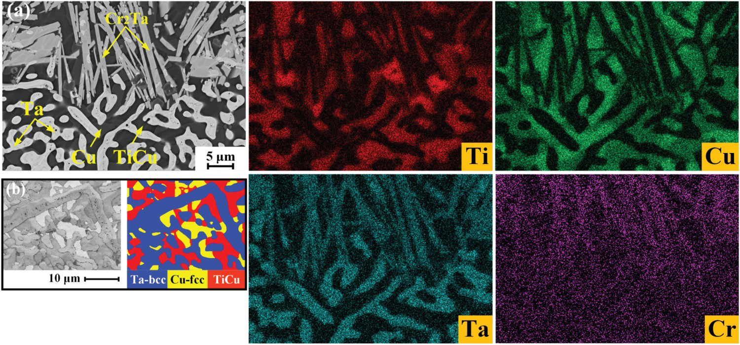
The EDS map scanning results of the very fine white equiaxed crystal in the red rectangular frame in Figure 3(c) are shown in Figure 5(a). It can be seen from the figure that the microstructure is mainly composed of a grey-black equiaxed structure and white reticular structure (about 1.0 μm in width). The results of the EDS show that the grey-black structure has a higher content of Ti and Cu. Meanwhile, the white and fine reticular structure contains more Ta. The LDM technology is characterised by fast heating and cooling. The solid solubility of Ta and Cu is low due to the difference in β-Ta (bcc) and γ-Cu (fcc) lattice types. In the liquid state with a high laser heat input, Ta and Cu are thoroughly mixed but insoluble with each other [25]. However, during the rapid cooling process of LDM, Ta will nucleate and solidify preferentially due to its much higher melting point than that of Cu. Furthermore, the flow of liquid Cu is restricted, so Cu can only solidify in the gap of solid Ta. As a result, the reticular structure is formed in this region. The results of the EBSD analysis show that the white reticular structure is β-Ta, while the grey-black equiaxed crystal is mainly composed of Ti2Cu and TiCu. Because the region is close to the Ta/TC4 interface, more Ti diffuses and migrates here. The eutectic reaction process of L→Ti2Cu + TiCu was promoted, and a certain amount of Ti2Cu + TiCu eutectic structure was formed [26].
Enlarged photo of the tissue morphology of the red rectangular frame in Figure 4(c): (a) microstructure and corresponding EDS map scanning result and (b) EBSD contrast photograph and phase distribution map.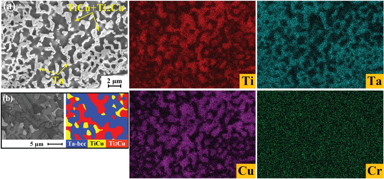
Evolution of phases of the bimetallic structure
Figure 6 shows the X-ray diffraction results of the TC4/Ta interface, Ta/Cu transition region, and Cu/Inconel718 interface in the TC4/Inconel718 bimetallic structure. The XRD results show that the TC4/Ta interface mainly contains α-Ti, β-Ti, and β-Ta, the Ta/Cu transition region mainly contains β-Ta, γ-Cu, Ti2Cu, and TiCu, and the Cu/Inconel718 interface mainly contains γ-Ni, γ-Cu, Cr2Ta, and laves. The Ta/Cu transition region inhibits the formation of Ti–Ni IMCs. However, a small amount of Ti–Cu and Cr–Ta IMCs is still formed in the bimetallic structure. This phenomenon is due to the fact that a cyclic heat input always accompanies the LDM process. At the same time, reducing the thickness of the transition layer makes it easier for elements in different regions to diffuse into each other. Owing to the high solid solubility between β-Ti in TC4 and β-Ta in Ta, Ti in TC4 diffuses easily upward into the Ta/Cu transition region. Therefore, the metallurgical reaction between Ti and Cu occurs in the middle and lower part of the Ta/Cu transition region to form Ti–Cu IMCs. In addition, Cu has a high solid solubility in Inconel718 and a high diffusion coefficient [27]. Therefore, during the LDM process, Cu and the main elements in Inconel718 will diffuse into each other. Cr in Inconel718 diffuses into the Ta/Cu transition region and reacts with Ta in the upper middle part of the Ta/Cu transition region to form Cr2Ta [24].
XRD of the interfaces of the bimetallic structure.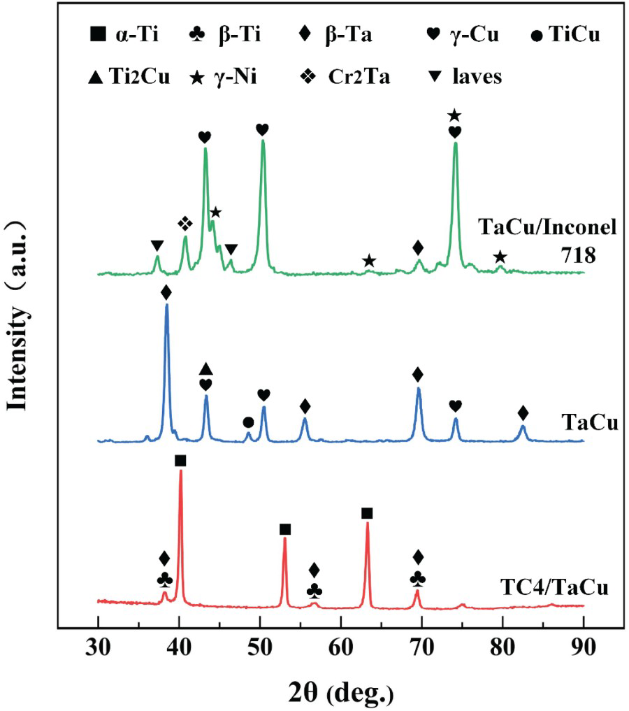
Vickers hardness of the bimetallic structure
The Vickers hardness results of the bimetallic structure sample are shown in Figure 7. The zero point marked in the figure is the centre position of the Ta/Cu transition region. It can be seen from the figure that the Vickers hardness values in the TC4 region and Inconel718 region of the bimetallic structure do not fluctuate much. The average Vickers hardness in the TC4 region is about 340.8 HV, which is almost equal to the deposited TC4 [15]. The average Vickers hardness of the Inconel718 region is about 294.0 HV, which is equal to the deposited Inconel718 [28]. It shows that there is no brittle phase in the TC4 region and Inconel718 region. However, the average Vickers hardness in the Ta/Cu transition region is about 361.6 HV and the highest value is about 444.0 HV. The Vickers hardness of Ta and Cu should be about 290 HV [29] and 280 HV [30], respectively. Based on the above microstructure analysis of the Ta/Cu transition region, it can be inferred that the higher Vickers hardness of the Ta/Cu transition region is mainly attributed to the formation of TiCu, Ti2Cu, and Cr2Ta. The IMCs in the transition region hinder the movement of dislocations and stacking faults, which further increase the Vickers hardness.
Vickers hardness of the bimetallic structure.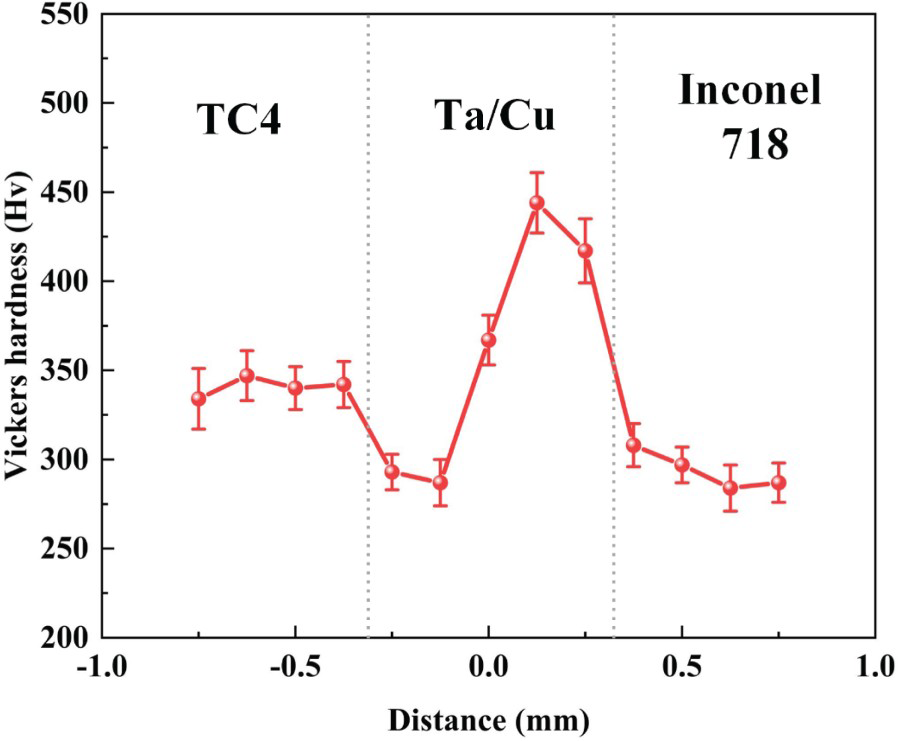
According to Shang et al. [31], the bonding region formed by titanium alloy and nickel-based contains many Ti–Ni IMCs, reaching a Vickers hardness of about 801.0 HV without the transition layer. In this work, the formation of the Ta/Cu transition region limited the direct bonding of TC4 with Inconel718, leading to a further reduction in the Ti–Ni IMCs. At the same time, the Ta/Cu transition region can also reduce the crack sensitivity in the bonding region and indirectly improve the bonding quality of the bimetallic structure.
Tensile properties of the bimetallic structure
The tensile specimen was prepared along parallel to the growth direction. It can be seen from Figure 8(a) that the Ta/Cu transition region is located on the parallel cross-section of the tensile specimen. The dark grey part should be the Ta layer, while the yellow-orange area should be the Cu layer. The fracture morphology is shown in Figure 8(b), in which obvious cleavage steps and tear ridges can be seen, which agrees with the characteristics of quasi-cleavage fracture. It can be seen from Figure 8(c) three specimens were evaluated in the tensile properties testing. The average tensile strength of the bimetallic structure is about 280 MPa, and the average elongation is about 0.52%. The stress–strain curve shows that there is no obvious yield stage, so it can be determined that the tensile specimen is a brittle fracture. Since the solid solution was mainly formed at the TC4/Ta interface and the Cu/718 interface, while the TiCu and Ti2Cu brittle IMCs were formed in the TaCu transition region, resulting in a weird elastic domain behaviour in the tensile curve of Figure 8(c). Based on the XRD results near the fracture surface (Figure 8(d)), a large amount of β-Ta and γ-Cu phases and a small amount of Ti2Cu brittle IMCs near the fracture can be observed. It shows that the fracture position is the Ta/Cu transition region of the bimetallic structure. The existence of the brittle phase limits the improvement of the mechanical properties of the bimetallic structure.
Room temperature tensile test of the bimetallic structure: (a) tensile specimen size, (b) fracture morphology, (c) stress–strain curve, and (d) XRD results near the fracture surface.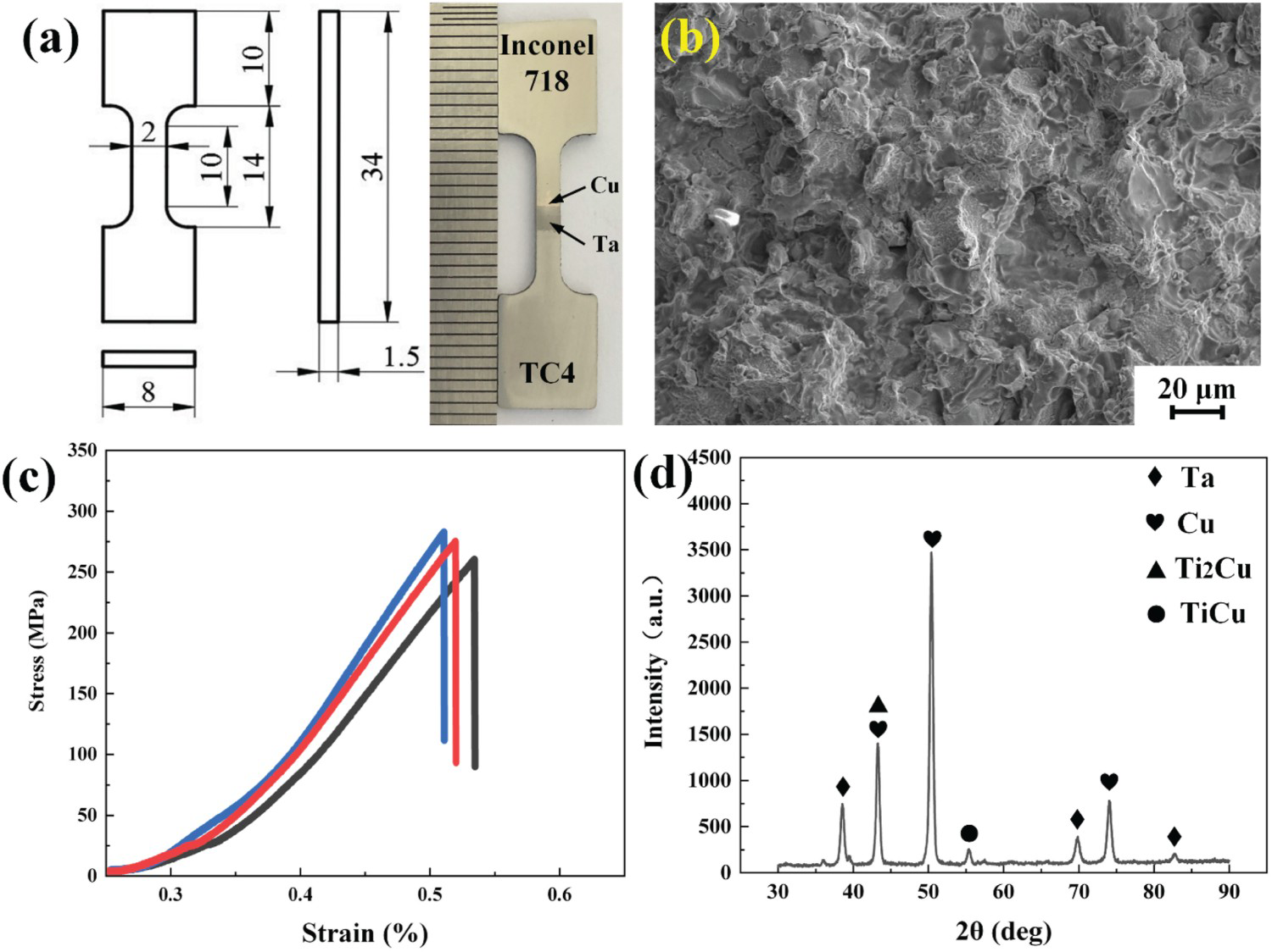
Conclusions
Based on the LDM technology, the TC4/Inconel718 bimetallic structure with the thinner Ta/Cu transition layer was fabricated to refrain undesirable Ti–Ni IMCs. The TC4 region, Ta/Cu transition region, and Inconel718 region were formed with good adhesion between each region without obvious cracks and gas pores. The corresponding phases compositions of the regions are α-Ti+β-Ti+β-Ta, β-Ta+γ-Cu + Ti2Cu + TiCu, and γ-Ni+γ-Cu + Cr2Ta + laves. The formation of the Ta/Cu transition region effectively inhibits the formation of the Ti–Ni brittle IMCs and reduces the crack sensitivity of the bimetallic structure. Ti–Cu and Cr–Ta brittle IMCs formed in the Ta/Cu transition region due to the elemental diffusion between the transition layers. The Vickers hardness of the Ta/Cu transition region is as high as 444.0 HV due to the formation of brittle IMCs. The tensile strength of the bimetallic structure at room temperature is about 280 MPa, and the fracture morphology is quasi-cleavage fracture formed by the brittle fracture. The fracture position of the tensile specimen occurs in the Ta/Cu transition region due to the presence of the brittle phase.
Footnotes
Disclosure statement
No potential conflict of interest was reported by the author(s).