
Abstract
Metal-inert gas welding is an important welding process but the process instability easily induces spatter and undercut defects. To improve the welding process stability, a new hybrid arc welding process, named KTIG–MIG, was proposed in this paper. Arc characteristics were preliminarily studied. It is found that in KTIG–MIG hybrid welding, MIG arc is stable even it is shielded with pure argon gas; stable spray transfer is easily achieved in a much wider process window, especially the lowest voltage to achieve spray transfer is greatly reduced; KTIG arc voltage decreases than that in single KTIG arc, and MIG arc current is higher than the pre-set value. Cooling state of the KTIG tungsten plays a key role in slowing tungsten erosion.
Introduction
MIG welding is widely used in engineering machinery, chemical equipment, shipbuilding, and other industries. It has the advantages of robust adaptability and easy automation and can be applied to weld almost all metal materials. However, to weld ferrous metals, such as carbon steel and low alloy steel, the arc stability is poor, resulting in bad weld quality [1]. To improve the stability of MIG arc, adding a small amount of oxidising gas in the pure argon shielding gas is a promising method. The instability of cathode spots is improved, but the addition of oxidising gas will increase the content of oxygen in the weld, and the toughness of weld metal may reduce [2]. Developing a hybrid heat source based on MIG arc is another way to improve the MIG arc stability and further improve the welding efficiency.
Kanemaru et al. [3] have developed the TIG–MIG hybrid welding by combining the TIG welding torch and the MIG welding torch. A current path formed between the TIG arc and the MIG arc promotes the stable burning of the MIG arc and overcomes the drifting of cathode spots. The TIG welding current or the interelectrode distance has an important influence on the stability of the TIG–MIG hybrid arc. Chen et al. [4] successfully used low current TIG arc to stable MIG arc in the high-speed welding of thin plates. It was found that the undercut defect was eliminated. Although the heat input was slightly higher than conventional MIG welding, the microstructure of the weld hardly deteriorated. Zong et al. [5] further studied the influence of the TIG current on the stability of TIG–MIG hybrid arc and weld quality in high-speed welding. The results showed that the interelectrode distance would affect the stability of TIG–MIG hybrid arc, a higher current was needed to achieve stable welding when the TIG arc was trailing posited. Compared with MIG welding, the TIG–MIG hybrid welding can get quality welding at a higher welding speed. However, the penetration ability of the TIG–MIG hybrid arc is still limited. To weld mid-thick plates, it still needs multi-pass welding to refill the prepared groove. Moreover, the current loading capacity of the tungsten electrode is limited. During the welding process, the tungsten electrode is inevitably heated by the MIG arc, and the erosion state of the tungsten electrode is dramatically accelerated and further shortens its service life.
Researches have been done to combine plasma arc with MIG arc. The coaxial plasma-MIG welding torch was first put forward by the Philips experimental research centre of the Netherlands [6]. Ono et al. [7] have successfully applied the coaxial plasma–MIG welding torch to weld aluminium alloy. The plasma arc pre-heats the wire and molten pool, welding spatter and fume were greatly reduced. Working environment and weld quality were hence greatly improved. Miao et al. [8] used bypass-current plasma–MIG hybrid arc welding to AA 5083 aluminium alloy welding and realised the precise control of droplet transfer behaviours. As reported by Resende et al. [9], the coaxial plasma–MIG welding torch has a wide nozzle, the heating region of the hybrid arc is larger, the heat source energy density gets decreased, and the weld was wide and shallow. In the paraxial plasma–MIG torch, the plasma arc and MIG arc are established separately, it has been successfully applied in mid-thick plate welding, for example, carbon steel was welded by Guo et al. [10], and aluminium alloy by Nguyen et al. [11]. Similar to the paraxial plasma–MIG hybrid welding process, the laser-MIG hybrid welding takes advantage of deep penetration in laser welding and high efficiency in MIG welding. The combination of MIG arc and laser significantly increases weld penetration and welding efficiency. The keyhole formed by the laser in the weld pool has a compression effect on the MIG arc, the arc stiffness is improved, and the droplet transfer behaviour is stable, as reported by Liu et al. [12]. But the high cost of laser equipment and maintenance limits its promotion in the industry.
KTIG welding is a high-current TIG welding technology that was proposed by Jarvis and Ahmed. [13]. In KTIG torch, a running water system is added to highly cool the tungsten electrode. The cathode electron emission area is restricted to a narrower area, the energy density and penetration ability are improved. It is also called CF-TIG (cathode-focused TIG) welding, as reported by Schnick [14]. KTIG torch has the advantages in aspects of simple structure and low cost. KTIG process can achieve keyhole mode welding in relatively low heat conductivity metals, for example, C-Mn steels by Lohse et al. [15], CP zirconium by Lathabai et al.[16], stainless steel by Feng et al. [17], CP titanium by Lathabai et al. [18]. Moreover, KTIG arc is wider than plasma arc and has a deeper penetration ability than TIG arc, the combination of a KTIG arc to a MIG arc should give new results.
To improve the stability and productivity in MIG welding, a hybrid welding process named KTIG–MIG is proposed in this research. The hybrid torch is developed, and several experiments were done to confirm the effectiveness and feasibility of the proposed KTIG–MIG hybrid welding. The current–voltage signals were compared with those of MIG welding to characterise the process stability. The surface quality and weld microstructure were compared and analysed. The tungsten erosion condition in KTIG–MIG hybrid welding under water-cooled state and gas-cooled state (similar to TIG–MIG hybrid welding) was also compared.
Modification principle
TIG–MIG hybrid welding overcomes the unstable phenomenon of cathode spot in argon-shielded MIG arc. Droplet behaviour changes from short-circuit transfer with large spatter to stable spray transfer, and the welding process stability is dramatically improved. TIG arc is a free arc and has limited penetration ability. To achieve a better coupling effect between TIG arc and MIG arc, the interelectrode distance should not be large, as tested by Meng et al. [19]. At such a small interelectrode distance, the MIG arc would have a thermal effect on the tungsten electrode. The tungsten electrode would run in a severe overheating state. Long-time welding will lead to TIG tungsten tip erosion or even melting. That is, the heat from the MIG arc gives a challenge to the TIG current loading capacity and the tungsten life length. The limited TIG arc current creates low penetration ability in the hybrid arc welding process. To weld a mid-thick workpiece, a multi-passes welding process should be conducted to refill the prepared groove, as reported by Kanemaru et al. [20]. The constrained plasma arc has much higher current density and arc pressure, deeper penetration weld is easily formed. Combination plasma arc with MIG arc, the tungsten in the nozzle avoids the MIG arc heating, but the large size plasma welding torch structure limits the close coupling between plasma arc and MIG arc.
In KTIG, the focused cathode region in the tungsten electrode tip makes the KTIG arc diameter narrower, it improves the energy density and arc pressure and further makes a deeper penetration. The KTIG arc diameter is much wider than the plasma arc. The KTIG–MIG hybrid welding process may have advantages: (1) the KTIG arc has increased energy density and arc pressure, the penetration ability is much improved, and the water-cooled effect on the tungsten electrode also improves the service life at high current; (2) compared with the plasma arc, the wider arc has a better stabilisation effect on the MIG arc, makes the KTIG arc and MIG arc could realise coupling closely. because of the smaller volume of KTIG welding torch, the droplet transfer behaviour should be easily to get stable. Therefore, the combination of KTIG arc and MIG arc is expected to give a new welding process, which has deeper penetration, less spatter and higher welding efficiency.
Torch setup and experimental system
As shown in Figure 1, the KTIG–MIG hybrid welding system consists of a home-made KTIG torch and a MIG torch, which are powered by a constant current mode welding power source (output capacity: 65–1000 A) and a constant voltage mode welding power source, respectively. The KTIG welding torch's axis was perpendicular to the workpiece, the tungsten rod diameter was 6.0 mm with a 30° tip angle. The distance from the tungsten tip to the workpiece ( Schematic diagram of KTIG–MIG hybrid welding system.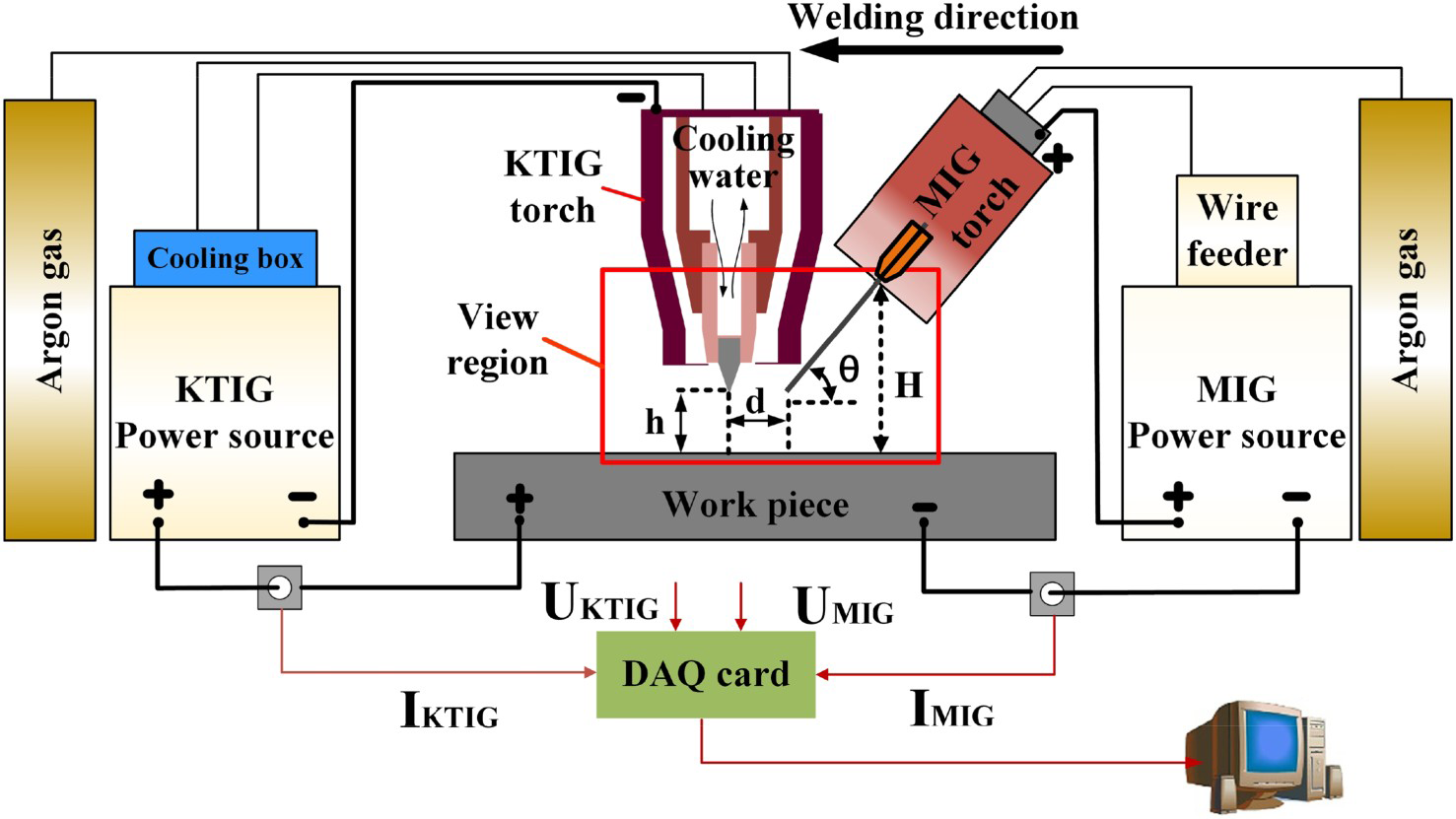
Experimental procedure
In this paper, the stability of the KTIG–MIG hybrid welding system was verified by experiments first. In Test 1, KTIG–MIG hybrid welding experiment and MIG welding experiment were carried out. In the KTIG–MIG hybrid welding experiment, the
Results and discussion
Droplet transfer
Figure 2 shows a group of sequential images of droplet transfer in MIG welding and KTIG–MIG hybrid welding. In MIG welding, the stability of the droplet transfer process was poor, the droplet transfer form is the large droplet transfer. Under the action of electromagnetic shrinkage force and gravity, the molten liquid metal at the wire tip overcame the surface tension and flew to the molten pool in a large droplet shape. Because the welding wire is forward inclined, the droplet detached and flew into the front of the weld pool, as shown in Figure 2(a). KTIG–MIG hybrid welding process is shown in Figure 2(b), the MIG arc length increases dramatically in the hybrid arc, the double-layer structure can be clearly seen in the MIG arc, the inner layer is metal vapour layer, and the outer layer is argon ion layer [21]. An arc plasma, bright white area between the two arcs, bridges the KTIG arc and MIG arc. The MIG arc current flows at the opposite direction from the KTIG arc current, the Lorenz force acts to reject the two arcs. The MIG arc and the liquid metal at the wire tip deflect and flow nearly perpendicular to the workpiece but not flows along the welding wire axis. The KTIG arc has a shorter length, but it still maintains the vertical flowing state and has invisible deflection. The droplet transfer changes to stable spray transfer, almost no spatter. The MIG welding wire tip became a slender liquid metal flow, it is deflecting backward under the action of the repulsion force from the KTIG arc. Under the combined action of the electromagnetic shrinkage force of the MIG arc, the Lorentz force of the KTIG arc and the gravity of the liquid metal, the metal at the end of the liquid metal flow overcame the surface tension and gradually shrank into a metal ball. When the gravity and downward repulsive force of the metal ball gradually greater than the surface tension, it detached from the liquid metal flow end and fell into the molten pool as a string of droplets.
Droplet transfer process, current–voltage signals and spray transfer process window. Continued.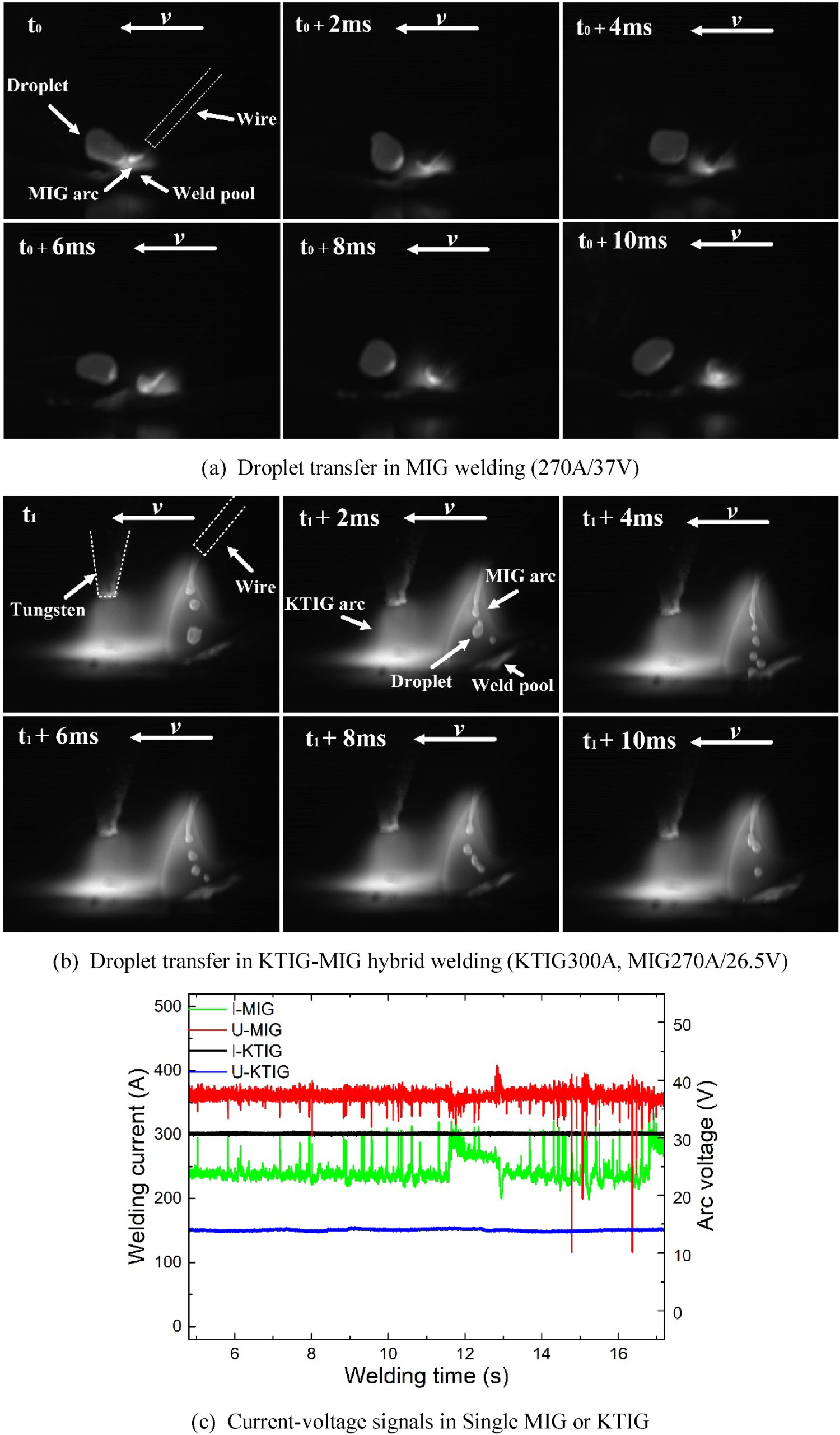
Current–voltage characteristics
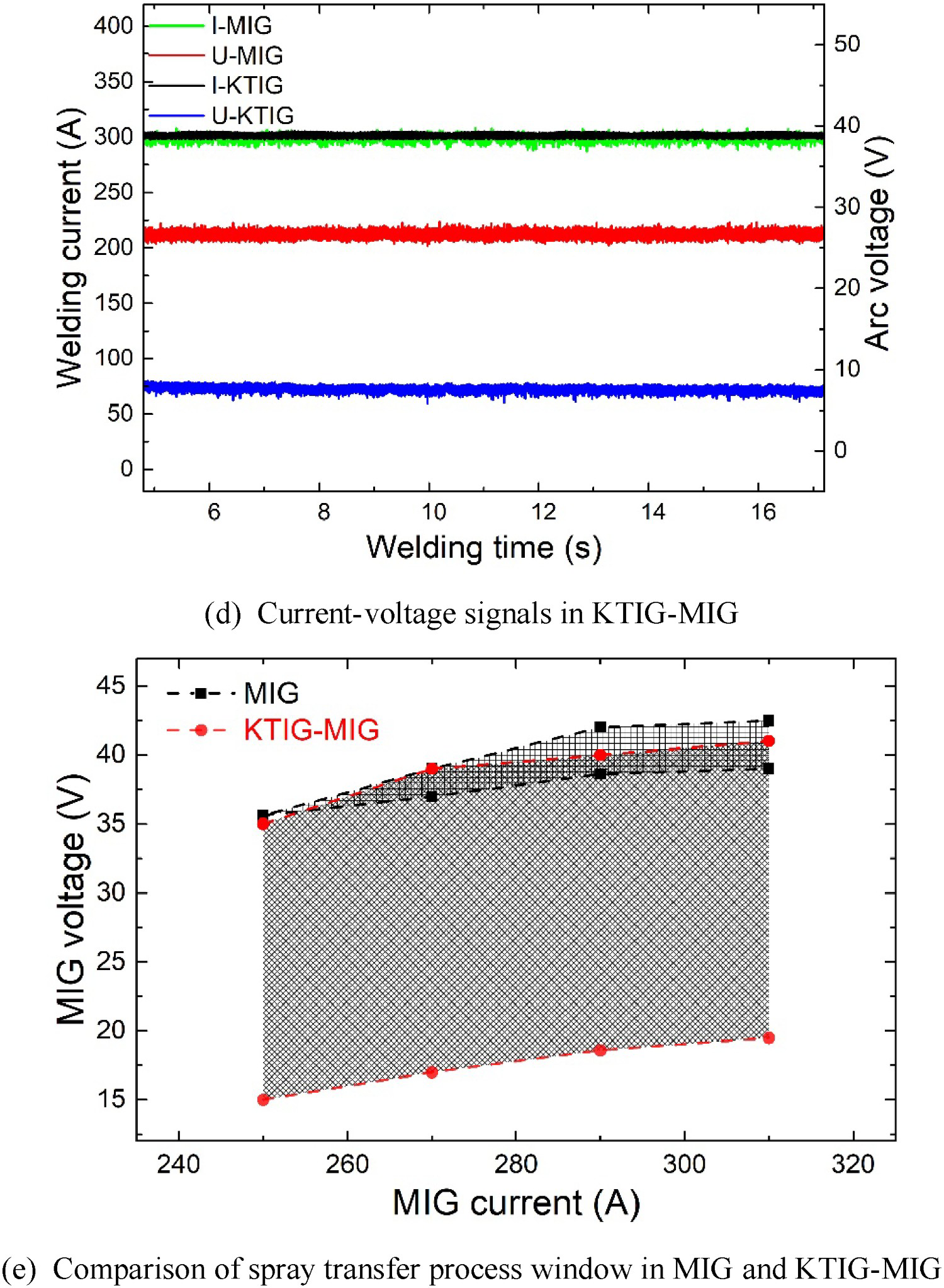
The current and voltage signals in a MIG welding or a KTIG welding are shown in Figure 2(c), and the current and voltage signals obtained in KTIG–MIG hybrid welding are shown in Figure 2(d). During the single MIG welding process, both current and voltage signals have significant fluctuation, for example, around the 12–16 s stage of MIG welding in Figure 2(c). The average value of
Process window
As shown in Figure 2(b) and (d), in KTIG–MIG hybrid welding, the welding process became very stable, and the MIG arc voltage to achieve stable spray transfer was far less than in the ordinary MIG welding. To explore the voltage-adjustable range of spray transfer in KTIG–MIG hybrid welding, test group 2 was conducted with the
Weld surface
Figure 3(a)–(h) shows the weld surfaces obtained in KTIG–MIG hybrid welding and MIG welding. At the same Weld surfaces and weld cross-sections melting depth in MIG and KTIG–MIG. Continued.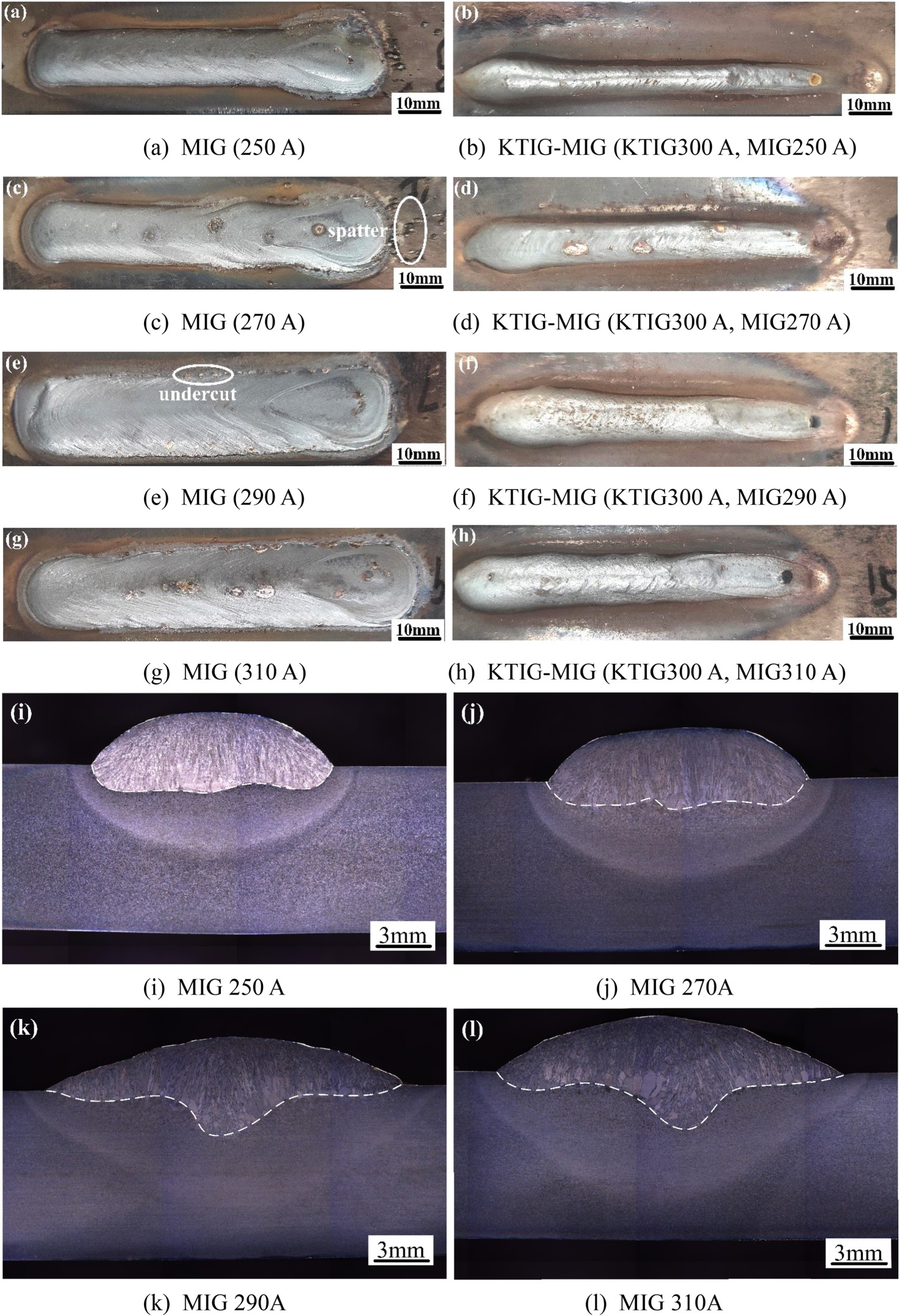
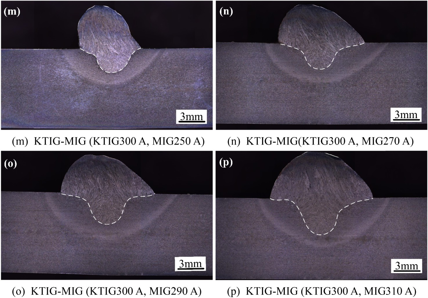
Figure 3(i)–(l) and (m)–(p) shows the cross-section of MIG welds and KTIG–MIG welds, respectively. The weld widths are larger and the weld melting depths are smaller in MIG welding. MIG weld width increases from 13.6 mm at 250 A to 20.1 mm at 310 A, the corresponding weld melting depth increases from 1.6 mm to 3.3 mm. At a given KTIG arc current of 300 A, KTIG–MIG hybrid weld width increases from 7.2 mm at MIG current of 250 A to 12 mm at MIG current of 310 A, and the corresponding weld depth increases from 2.9 mm to 4.3 mm. The forward-inclined MIG torch caused the MIG arc extension along the welding direction, as shown in Figure 4(a), the arc plays a role in pre-heating and expanding the heating region but not increasing the melting depth. In KTIG–MIG hybrid arc process, as shown in Figure 4(b), the leading KTIG arc has a robust thermal and force effect on the workpiece, a deep penetration weld is formed; repulsed by the electromagnetic force of the KTIG arc, the MIG arc flows towards the weld pool in the vertical but not inclined direction. That is, in the KTIG–MIG hybrid arc process, the arc pressure from the two arcs and transferred droplet flow coupling force the heat to deposit into the molten pool bottom.
Arc behaviour.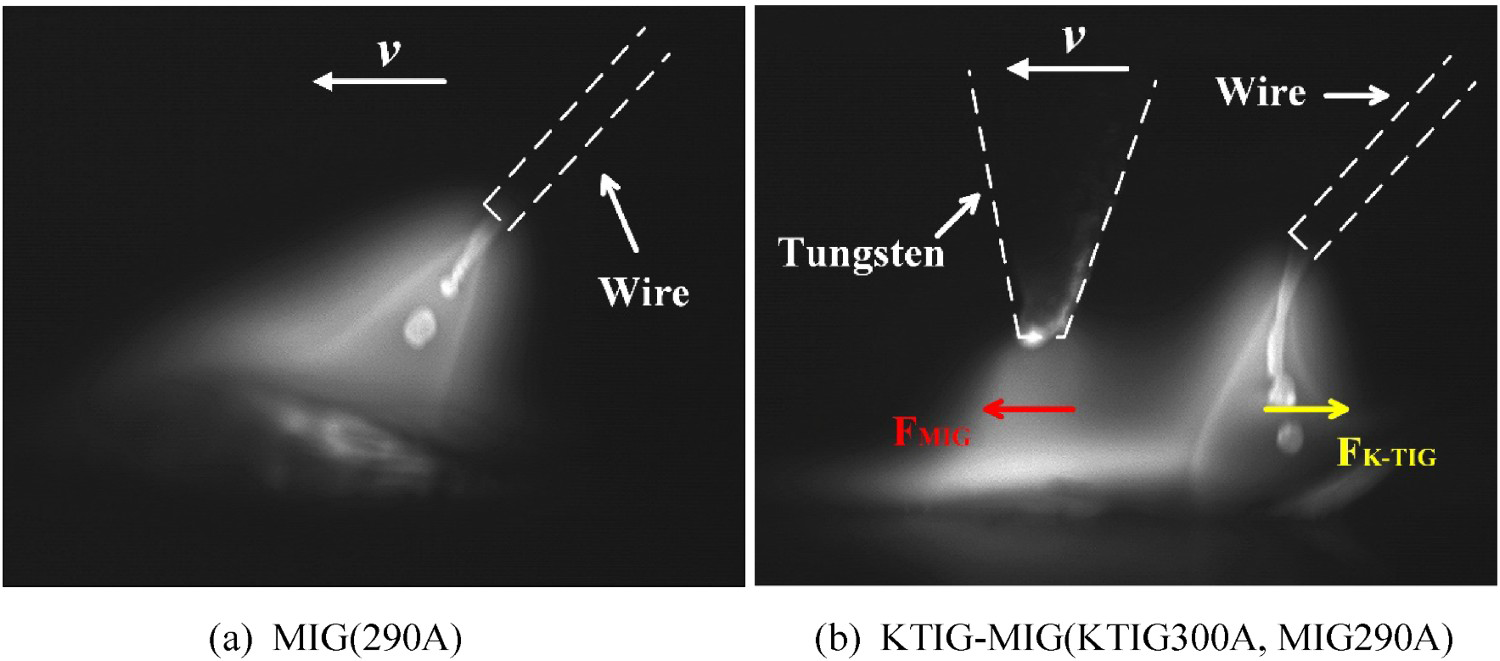
Microstructure and microhardness
The microstructure in MIG welds and KTIG–MIG welds is shown in Figure 5. A weld for 16Mn includes the fine grain zone (FGZ), coarse grain zone (CGZ), fusion zone (FZ) and welded metal zone (WMZ), as shown in Figure 5(a) and (f). The FGZ in MIG weld has fine grain, as shown in Figure 5(b), it is mainly composed of equiaxed ferrites (white) and pearlites (black). They are all transferred from fine austenite grains. The CGZ, as shown in Figure 5(c), contains many blocky or needle-like coarse proeutectoid ferrites, it nucleates at the grain boundaries during the cooling period, and then grows along the grain boundary or grows into the grain. The severe overheating in this zone also leads to the formation of Widmanstatten structures. It is generally believed that the Widmanstatten structures could reduce the mechanical properties of steels, especially the plasticity and impact toughness, and increase the tough-brittle transfer temperature [22]. Pearlites were also found between proeutectoid ferrites. FZ is adjacent to the WMZ and the heat-affected zone (HAZ), as shown in Figure 5(d), microstructures in this area are inhomogeneity. There are fine acicular ferrites distributed inside the grain, bainites and Widmanstatten structure, and coarse proeutectoid ferrites grew from the fusion line to the centre of the weld along the direction of the columnar grain. The microstructures in WMZ (Figure 5(e)) are mainly composed of coarse proeutectoid ferrites precipitated along grain boundaries and fine acicular ferrites formed in the grains, it also contains a small number of pearlites.
Microstructure in MIG weld and KTIG–MIG weld(290A). (a)–(e) overall, FGZ, CGZ, FZ, WMZ in MIG weld; (f)–(j) overall, FGZ, CGZ, FZ, WMZ in KTIG–MIG weld. Continued.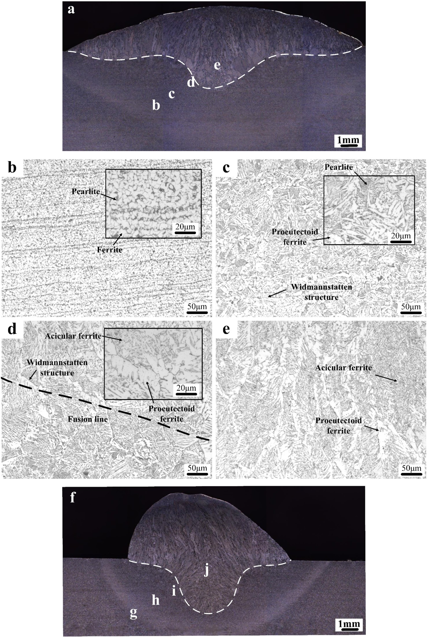
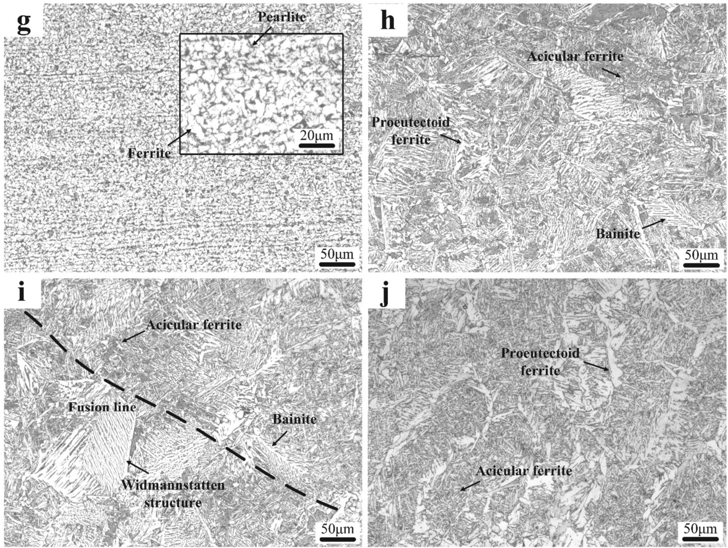
The microstructure of KTIG–MIG weld in different zones was shown in Figure 5(g)–(j). In the FGZ, as shown in Figure 5(g), the microstructures are also composed of fine ferrites and pearlites, similar to that of MIG weld, and there was no significant difference in grain size between them. In the CGZ, as shown in Figure 5(h), the size of the microstructure was significantly refined compared to the MIG weld, the number of coarse proeutectoid ferrites decreased, while the number of ferrites side plate was increased. The number and size of the Widmanstatten structure are both reduced. In Figure 5(i), the microstructure in the fusion zone is still characterised by nonuniformity. The microstructure also included Widmanstatten structure, acicular ferrites and proeutectoid ferrites growing along the heat flow direction towards the weld centre. The microstructure of the WMZ is similar to that in MIG weld, mainly composed of proeutectoid ferrites and acicular ferrites. The difference is that the number of acicular ferrites increased and the number of coarse proeutectoid ferrites decreased.
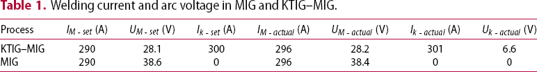
Welding current and arc voltage in MIG and KTIG–MIG.
The calculation formula of welding heat input is as follows:
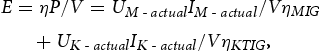
To evaluate the weld performance, Vickers microhardness test was carried out. The test line is 1.0 mm below the workpiece top surface. The microhardness curves in MIG and KTIG–MIG are shown in Figure 6.
Microhardness.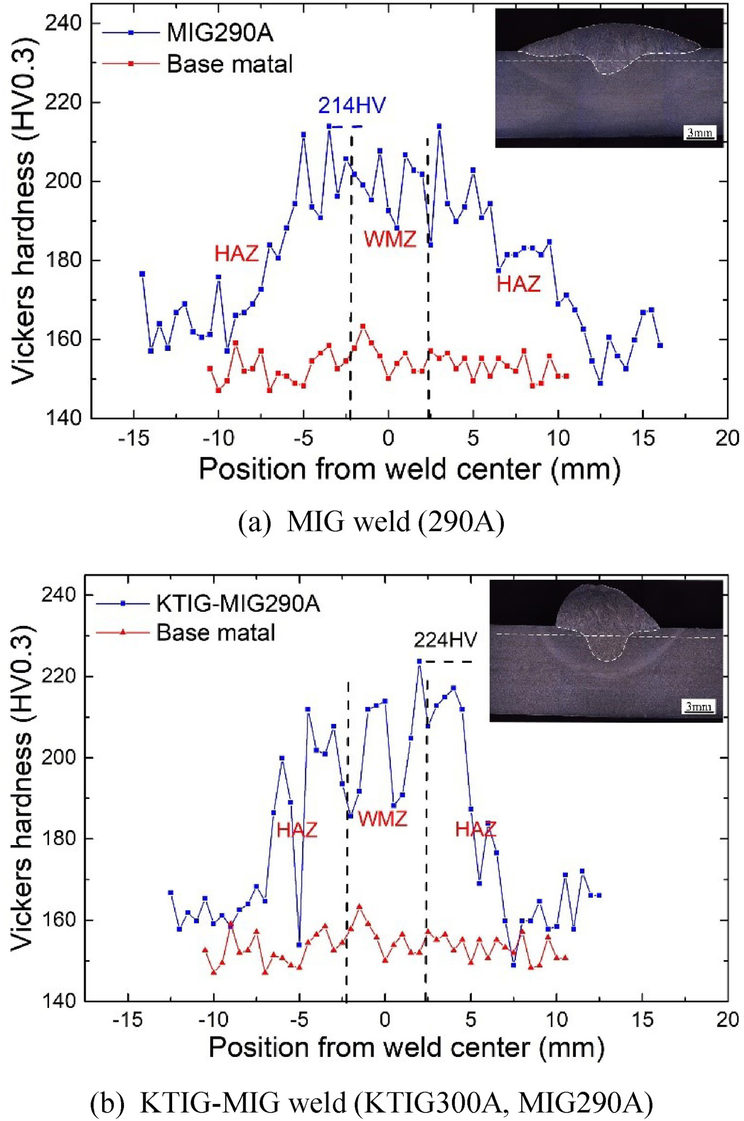
Different zones, such as WMZ, HAZ and BM (base metal), can be distinguished by microhardness curves. Both in MIG and KTIG–MIG weld, the microhardness of the WMZ and HAZ was higher than BM. The highest hardness values of MIG weld appear in the HAZ, and that of KTIG–MIG weld appear in the WMZ, they were adjacent to FZ. The maximum hardness of weld in KTIG–MIG weld is 224HV, as shown in Figure 6(b), which is higher than that of MIG welding. This was related to the decrease of welding heat input. When the welding heat input is decreased, the stay time of weld metal at high temperatures becomes shorter, so the content of ferrites decreased while the content of pearlites and bainites increased. This improved the microhardness of the weld.
Comparison of tungsten tip erosion behaviour
Figure 7 shows the morphology of the tungsten electrode in its original state and water-cooled or gas-cooled after welding in the hybrid welding. It was found that when the tungsten electrode was cooled by the running water in the KTIG torch, there was little erosion. However, when the running water in the KTIG torch is turned off during the welding process, the tungsten rode wall is only cooled by the shielding gas, the tungsten works as in the TIG–MIG hybrid welding process, and severe erosion and even melting occurred at the tip and side of the tungsten electrode. The erosion affects the arc characteristics during welding, and seriously reduced the tungsten service life. That is, KTIG–MIG hybrid torch system has a longer life than TIG–MIG hybrid torch system.
Tungsten morphology.
Conclusion
KTIG–MIG hybrid welding achieves a stable welding process, the droplet transfer changes to stable spray transfer, and the service life of the tungsten electrode is significantly improved. The spray transfer in KTIG–MIG hybrid welding is easier to realise, the voltage adjustment range is greatly expanded. Compared with MIG weld, the weld obtained in KTIG–MIG hybrid welding has a larger weld penetration depth and smaller weld width. At the given MIG arc current, the microstructure of the coarse grain zone and welded metal zone in KTIG–MIG weld is finer.
Footnotes
Disclosure statement
No potential conflict of interest was reported by the authors.