
Abstract
The root defect is easy to occur in the conventional friction stir welded (C-FSW) Ti/Al dissimilar joints because of the thermophysical properties of titanium alloy. Double-side friction stir welding (DS-FSW) may be a solution to eliminate root defects. This work performed microstructure analyses of the Al/Ti interface for both C-FSW and DS-FSW joints and comprehensively investigated the effects of root defects. The results show that the mechanical properties of the Al/Ti C-FSW joints are severely weakened by root defects. Tensile strength of the DS-FSW joints was 310.8 MPa, which is 73 MPa high than the C-FSW joints. The DS-FSW process can effectively remove the root defects which offers a novel approach to achieve high-quality joining of Al/Ti dissimilar structures.
Keywords
Introduction
Aluminium/titanium hybrid structure has been widely used in many fields [1]. However, the significant differences in their thermophysical properties make it difficult to achieve high-quality joints through traditional fusion welding methods [1]. With the continuous development of welding technology, various welding methods have been used to produce Al/Ti dissimilar joints with excellent performance, such as laser welding [2] and vacuum diffusion welding [3]. In contrast to fusion welding, friction stir welding (FSW) has the ability to prevent hot cracks and porosity, which makes it a promise method for joining dissimilar structures, such as Al/Ti dissimilar alloys [4–6].
In recent years, many efforts have been done to achieve high-quality Al/Ti dissimilar joints by conventional friction stir welding (C-FSW) [7–9]. However, C-FSW suffers from an inherent issue which is a lack of root penetration defect at the bottom of the welded joints since the tool pin is short than the plate thickness [10]. It is even more pronounced in Al/Ti dissimilar joints. It results in the formation of a kiss bonding structure or root flaws at the bottom of joint and reduces its mechanical properties [11]. Ma et al. joined a 2 mm thick Al/Ti plate using an FSW tool with a 1.9 mm length pin, but they still found significant root defects at the bottom of the weld [9]. This suggests that the cause of the root defects is not only attributed to the pin length. It can be seen from the weld cross-section shown in the literature also implies there is not any severe plastic deformation of the titanium alloy at the weld root [11–14]. This is mainly because the low heat conductivity of Ti alloy which lead to a severe temperature difference between the upper and lower portions of the weld during the C-FSW process. Therefore, the material at the bottom of the weld is difficult to flow, resulting in the root defects in the Ti/Al dissimilar FSW joints. The plastic material near the weld root is difficult to flow to forming a vortex-like structure, ultimately leading to produce the root defect [15]. Moreover, this phenomenon will become more evident with increasing plate thickness and significantly deteriorate the mechanical properties of the joints [11].
There are two main approaches to addressing the problem of weak bonding at the root of the weld. One is redesigning the FSW tool [16–18]. The other is optimising and modifying the process [10,19]. Redesigning the FSW tool can solve the issue, but it also brings problems such as increased heat input, the complexity of the tooling and reduced workpiece clamping stiffness. In particular, increased heat input is fatal for the connection of dissimilar materials, as it leads to an increase in IMCs and a deterioration of joint performance. Therefore, DS-FSW has become one of the effective ways to solve the problem by modifying the process based on the existing tool design. In reference [19], DS-FSW have been used to join Al/Ti medium-thick plates up to 8 mm in thickness, and a maximum tensile strength can reach 265 MPa.
In the present study, an investigation was carried out to explore the effect of welding speed on the tensile strength of dissimilar Al/Ti C-FSW joints. The influence of root defects on the joint properties under the optimal welding parameters was analysed by removing the weld root. DS-FSW was employed to produce the Al/Ti joint without root defect to explore its advantages in enhancing joint properties.
Experimental detail
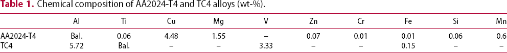
This study employed 4 mm-thick AA2024-T4 and TC4 alloy plates as the base materials for butt jointing through both C-FSW and DS-FSW. The chemical compositions of the base material are listed in Table 1. The schematic of the Ti/Al dissimilar FSW is illustrated in Figure 1(a). In both DS-FSW and C-FSW processes, TC4 and AA2024 alloys are consistently located on the advancing side (AS) and the retreating side (RS), respectively. The welding direction (WD) is always perpendicular to the rolling direction (RD). The normal direction (ND) is perpendicular to the WD and RD, as shown in Figure 1. The FSW tool always rotates counterclockwise regardless of the welding conditions. In the DS-FSW process, the second-pass weld starts at the back of the end of the first-pass weld after the first-pass weld is completed. Further details about the DS-FSW process can be found in the literature [19]. Figure 1(b and c) present the specific dimensions of the FSW tool and the offset utilised during C-FSW and DS-FSW. The illustrations depict that a significant portion of the FSW tool is situated at the AA2024 alloy to safeguard the pin. Initially, the experiment focused on investigating the process window of C-FSW, and the welding speed was uniformly varied from 15 to 60 mm/min while maintaining a tool rotational speed of 400 rpm. The tilt angle and plunge depth of shoulder are 2.5° and 0.2 mm, respectively. Once the optimal parameters were identified, the DS-FSW process was employed for further optimisation of the joint properties. When the welding is finished, wire electrical discharge machining was used to cut the tensile and metallographic samples, and their tensile characteristics were tested using a universal testing device at a loading rate of 1 mm/min. Three tensile specimens were measured for each condition. The specific dimensions of the tensile sample are shown in Figure 2(c). The cross-sectional morphology of the welds was analysed under an optical microscope after etching with Keller reagent [19]. The Al/Ti joining interfaces were analysed utilising a JSM-7800F field emission scanning electron microscope (SEM) equipped with an energy dispersive spectrometer (EDS).
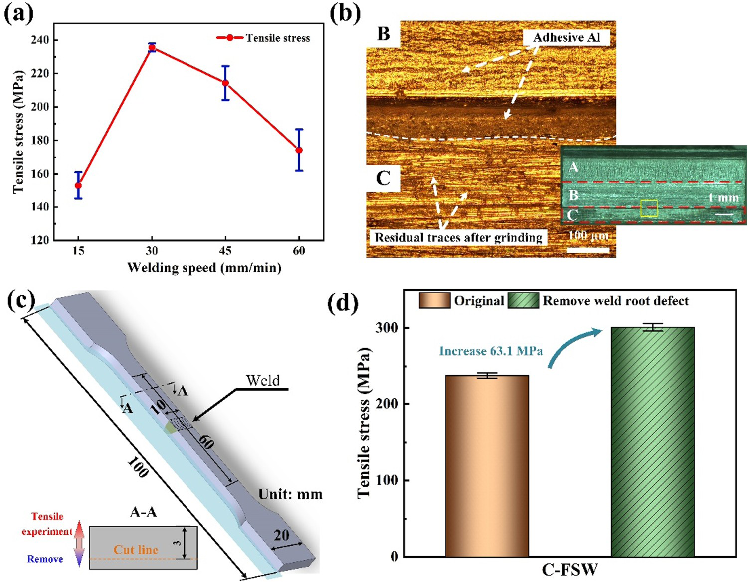
(a) Schematic of Ti/Al dissimilar FSW, (b) the tool dimension and tool offset in C-FSW, (c) the tool dimensions and tool offset in DS-FSW. (a) Variation of tensile strength of C-FSW joints with welding speeds, (b) typical fracture morphology of C-FSW joint, (c) schematic diagram of removing root defect, (d) comparison of tensile stress between the original joint and the one removed the root defect. Chemical composition of AA2024-T4 and TC4 alloys (wt-%).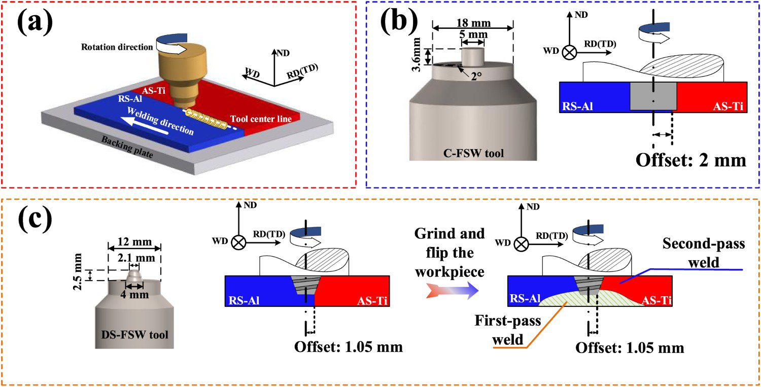
Results and discussion
Influence of weld root defect on C-FSW joint properties
Initially, the optimisation of the Al/Ti dissimilar C-FSW process was performed. Figure 2(a) illustrates the variation of average tensile strength with welding speeds. As evident from the image, the tensile strength of the C-FSW joint exhibits an initial increase followed by a decrease with the rise in welding speed. It is consistent with Li et al. [20]. The welding heat input decreases when welding speed raises, which may reduce the metallurgical bonding at the Al/Ti interface. However, the formation of excessively thick IMCs at the Al/Ti interface at the welding speed is 15 mm/min because of the larger heat input, which would also reduce the joint properties. The maximum average tensile strength of 235.6 MPa is achieved at the welding speed of 30 mm/min.
The fracture morphology of the Ti alloy side can be divided into three regions, namely A, B, and C, as shown in Figure 2(b). The adhesion phenomenon of aluminium alloy in region A is more noticeable. The reason is that it is closer to the shoulder, and the temperature is higher during the welding process, which is conducive to the metallurgical bonding of the Al/Ti interface. And no significant adhesion of aluminium alloy is observed in region C in contrast to regions A and B. Many residual traces of grinding before welding were observed in region C. This means that there is probably not enough metallurgical bonding in the region C. It becomes a weak area during the tensile test. The crack will first form in this region, then extend to the B region, and finally break. This is an inherent problem in the C-FSW process as the pin length is less than the plate thickness [10]. The lower heat input and high flow stress of titanium alloy increases the tendency of forming root defects during the Al/Ti dissimilar FSW process. It depicts that the joint tensile property is increased up to 300.9 MPa after removing the root defect in the C-FSW Al/Ti dissimilar joints as shown in Figure 2(d). It is evident that root defects have a significant impact on the tensile strength of the joint. Although increasing the welding heat input may have the potential to reduce or prevent weld root defects [13]. Notably, the experiment results indicate that higher heat input leads to the formation of thicker IMCs layers and subsequently deteriorates the joint performance, as shown in Figure 2(a) [13,21].
Comprehensive comparison of C-FSW and DS-FSW
Weld morphology
Figure 3 illustrates the typical weld morphologies of C-FSW and DS-FSW conducted at the rotation speed of 400 rpm with a welding speed of 30 mm/min. The images reveal a clear boundary between the TMAZ and HAZ on the aluminium alloy side. On the contrary, it is challenging to soften the TC4 alloy and induce severe plastic deformation on the titanium alloy side due to the relatively low temperature during Al/Ti dissimilar FSW. Moreover, the titanium particles observed in the DS-FSW joint were larger compared to those in the C-FSW joint. In C-FSW, the tool offset was maintained at 2 mm, which resulted in only 0.5 mm of the area being inserted into the titanium alloy. However, the tool offset was 1.05 mm in DS-FSW, and the conical shape of the tool caused more titanium alloy to be stirred at the root of the pin. This slight difference led to the formation of larger titanium particles in the DS-FSW joint. Figure 3(a and c) show a considerable reduction in the size of the SZ for the DS-FSW as compared to C-FSW. This phenomenon mainly attributes to the employment of a significantly smaller tool size in DS-FSW. More notably, a weld root defect was found at the bottom of the C-FSW joint, as shown in Figure 3(a and b). Sound weld without unwelded root defect is achieved in the DS-FSW as shown in Figure 3(c).
Typical weld morphology of (a-b) C-FSW and (b) DS-FSW conducted at the rotation speed of 400 rpm and 30 mm/min.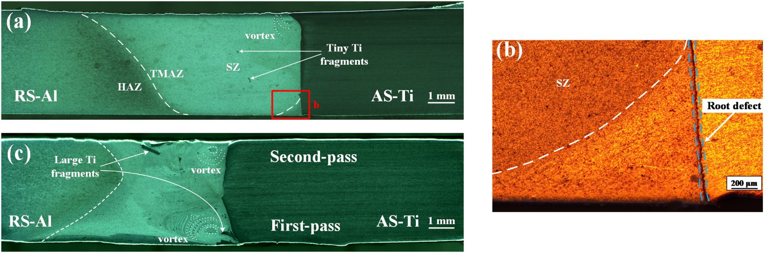
Interface microstructure
The microstructure of the Al/Ti interface plays a crucial role in determining the mechanical properties of the joints. Figure 4(a) displays the weld macrograph of the C-FSW joint and shows the position of the corresponding microstructure region in Figure 4(b-f). Micrographs show that there is not a large number of continuous micron scale IMCs at the Al/Ti interface. A small amount of uneven thickness of IMCs is found in Figure 4(c). Excessively thick IMCs cause large stress concentrations near the Al/Ti interface and deteriorate the performance of the joints [13]. Therefore, a suitable interfacial metallurgical reaction promotes the joint properties under this welding condition. The titanium particles near the interface after being broken by the FSW tool are found in Figure 4(d). At high temperatures, these particles react with the aluminium alloy to produce IMCs. The EDS data from point P1 is listed in Table 2. It indicates that the titanium composition at this point is 51.3%, while the aluminium composition is 48.7%. Considering the various types of IMCs between Al and Ti alloy that can form during FSW process, it is inferred that the possible IMCs phase is AlTi [22,23]. Figure 4(d) shows a less straight Al/Ti bonding interface than other regions. The interpenetration structure of aluminium alloy and titanium alloy is beneficial to improve the performance of the joint to a certain extent [15]. It should be noted that a unwelded defect was discovered at the root of the joint. Figure 4(e and f) illustrate the location of root defect. It is evident that the root defect formed in an area that was not directly stirred by the pin tip. In the previous experiment, it was found that the joint performance was significantly improved after the unwelded root was removed as shown in Figure 2(d). Therefore, how to reduce or avoid the occurrence of unwelded root defects are need to be considered in the actual experiment.
The weld microstructure of C-FSW joint, (a) Macroscopic SEM image of the Al/Ti interface and the schematic diagram of the location of the microstructure characterization, (b)–(f) SEM image and line scanning results of corresponding regional microstructure marked in Figure 4(a).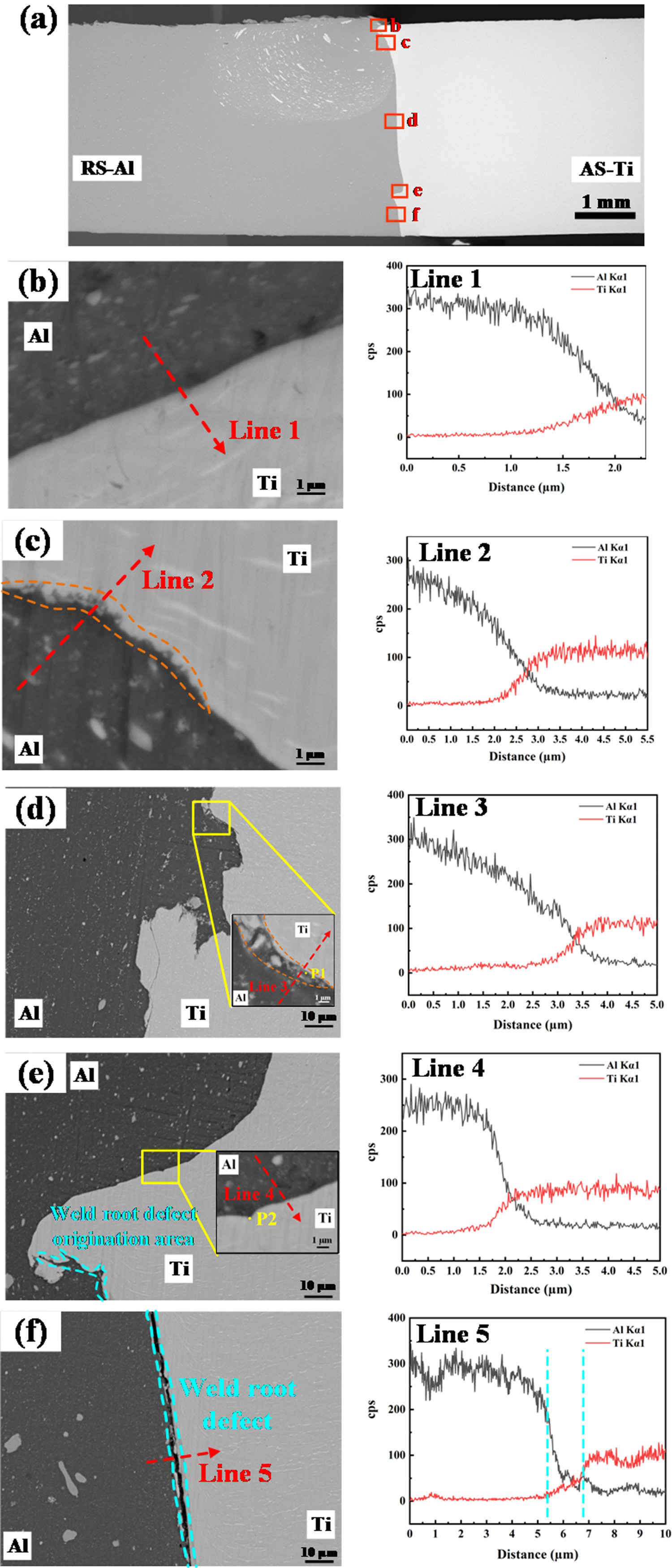
The section investigates the microstructure of a dissimilar Al/Ti joint produced by the DS-FSW process. Figure 5(a) displays the microstructure of the joint where the first-pass weld is located at the bottom of the workpiece, and the second-pass weld is located at the upper part. Due to the cone-shaped DS-FSW tool, the Al/Ti interface presents a non-vertical shape after welding. The investigation reveals that IMCs in the DS-FSW process were predominantly located near the tool-workpiece (T-W) interface as shown in Figure 5(b, f and g). Figures 5(c-e) show the formation of a diffusion interface after being stirred by the FSW tool. At the same time, there are no unwelded defects in the centre of the weld, i.e. in the lower part of Figure 5(d). This demonstrates that the DS-FSW tool is able to completely penetrate the entire workpiece after two-passes of welding to avoid the formation of unwelded defects. Figure 5(e) shows a small amount of Cu enrichment, which is thought to be the result of Cu precipitation along grain boundaries in the aluminium matrix after the FSW process [24]. Figure 5(g) shows the observation of multilayered IMCs. The location of these IMCs was found to be consistent with the results of Kar et al. [21]. The presence of these IMCs plays a crucial role in controlling the frictional behaviour between the tool and the workpiece, which is directly related to the temperature changes during the welding process. However, the thickness of the IMCs layer in the first-pass weld was found to be significantly thicker than that of the second-pass weld. It could be attributed to the welding deformation after the first-pass welding [19]. During the second-pass welding, the workpiece exhibited an inverted ‘V’ shape after clamping, resulting in a lower shoulder plunge depth [19]. It causes a decrease in downforce and heat input. This is also evident by the macrostructure image which depicts a narrow SZ of the second-pass weld compared with the first-pass weld, as shown in Figure 3(b).
The weld microstructure of DS-FSW joint, (a) Macroscopic SEM image of the Al/Ti interface and the schematic diagram of the location of the microstructure characterization, (b)–(g) SEM image and line scanning results of corresponding regional microstructure marked in (a).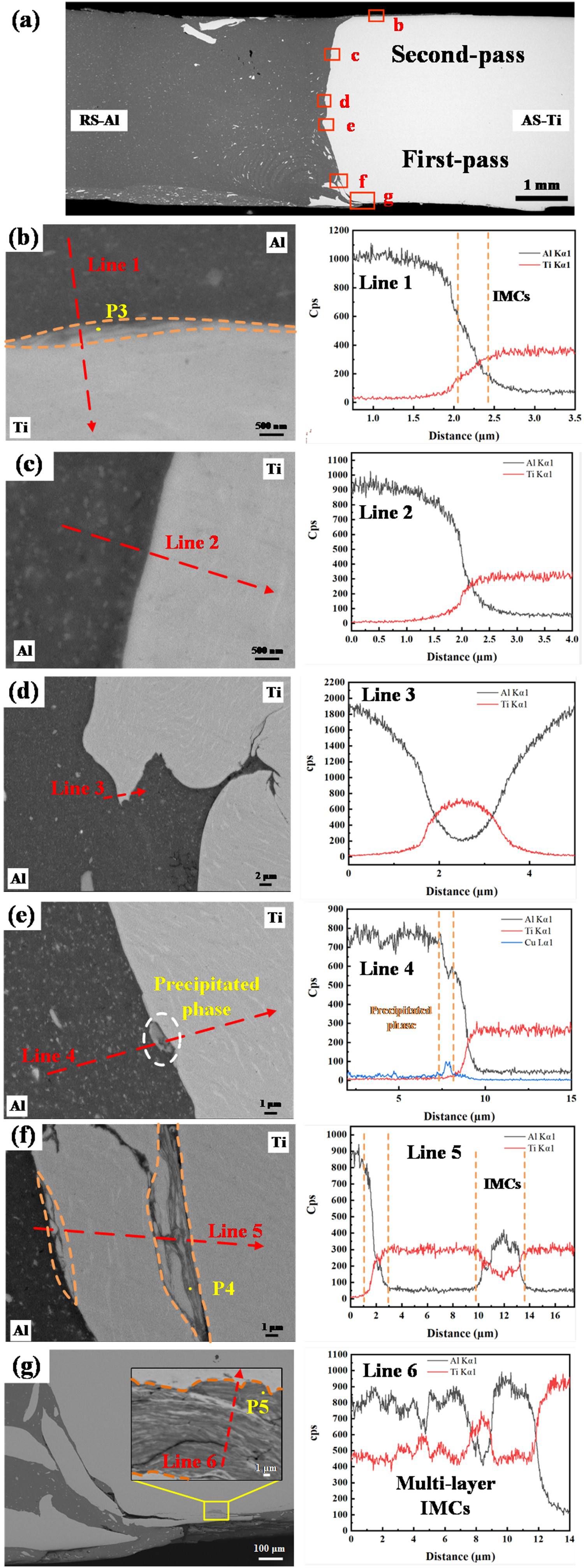
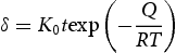
Comparing the IMCs in C-FSW with that in DS-FSW (as shown in Figure 4 and 5). It is evident that the IMCs present at the top of the first-pass weld of DS-FSW are significantly thicker than those in C-FSW. The thickness of IMCs is influenced by multiple factors, and can be mathematically expressed through the formula [25,26],
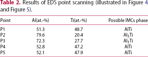
The formation of IMCs is representative of metallurgical reactions at the Al/Ti interface. An understanding of the IMCs types is crucial for comprehending the thermodynamic behaviour of the Al/Ti interface. Therefore, Table 2 presents the EDS point scanning results obtained at corresponding positions in Figure 4 and Figure 5. The table reveals that the primary IMCs produced during FSW are Al3Ti and AlTi. Al3Ti exhibits the lowest Gibbs free energy among Al/Ti intermetallic compounds, thereby leading to its formation as the primary intermetallic compound during the FSW process [22]. The formation of AlTi is strongly influenced by the diffusion of aluminium atoms during the welding process. The diffusion coefficient of aluminium atoms in titanium is higher than that of titanium atoms in aluminium, which means that conditions favouring higher heat input and lower plastic deformation rates are more conducive to the diffusion of aluminium atoms. Thus, more AlTi IMCs appeared at the top of the first weld of DS-FSW (i.e. P4 and P5).
Mechanical properties
Figure 6 presents a comparison of the tensile stress between C-FSW and DS-FSW joints, which are both conducted at the rotation speed of 400 rpm and the welding speed of 30 mm/min. The ultimate tensile strength of the DS-FSW joint reaches 310.8 MPa and represents an increase of 73 MPa compared to C-FSW. Meanwhile, less IMCs were found at the Al/Ti interface in both C-FSW and DS-FSW joints, as shown in Figure 4 and 5. This indicates that reducing the thickness of IMCs layer at the Al/Ti interface is beneficial to enhance the joint performance. However, the root defects generated in the C-FSW process prevent a further enhancement of the joint performance. The mechanical properties of the DS-FSW joint are higher than the C-FSW joint which removed the root defects. The negative influence of weld root defects on joint performance can be eliminated by the DS-FSW, and the experimental results show a markable improvement in the joint mechanical properties. Therefore, DS-FSW provides an excellent solution to achieving high-quality Al/Ti dissimilar welded structure by eliminating the weld root defect in C-FSW joints.
Comparison of tensile of C-FSW and DS-FSW joints achieved at the rotation speed of 400 rpm with the welding speed of 30 mm/min.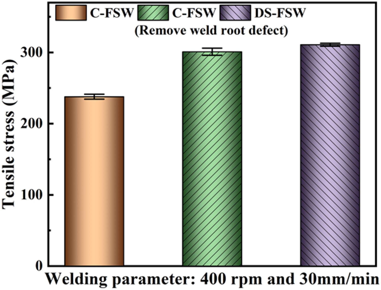
Conclusions
Root defects are easy to occur in the Al/Ti conventional friction stir welded (C-FSW) joints since the length of the tool pin in the C-FSW must be less than the plate thickness. The maximum tensile strength of Al/Ti C-FSW joint is 235.6 MPa. While removing the weld root defect can increase the tensile property of the joint up to 300.9 MPa. Double-side friction stir welding (DS-FSW) can eliminate the detrimental of the weld root defect. The tensile strength of DS-FSWed Al/Ti dissimilar joints is even higher than the C-FSW joints which have removed the weld root defect. The DS-FSW of AA2024 and TC4 plates exhibits a maximum tensile strength of 310.8 MPa, which is increased by 73 MPa compared with the C-FSW joint. It indicates that DS-FSW is an excellent variant of FSW to eliminate the weld root defect in Ti/Al dissimilar C-FSW joints.
Footnotes
Disclosure statement
No potential conflict of interest was reported by the author(s).