
Abstract
Mechanoluminescent (ML) phosphors are ideal components for the structural health monitoring (SHM) of in-service fibre-reinforced composites (FRCs); the integration of ML phosphors however, has proven difficult due to ML phosphor properties such as density, morphology and chemical structure. This paper seeks to address such processing difficulties through the utilisation of the novel displaced foam dispersion (DFD) technique. The displaced foam dispersion (DFD) technique is a particular method for manufacturing particulate composites in which particulates are integrated into expendable PS foams. The foams are then placed between fibre fabrics and dissolved upon the infusion of vinyl ester (VE) resin, leaving the particulates in place. Herein, ML-FRCs using two varieties of ML phosphors are manufactured via the DFD technique followed by short beam shear (SBS) testing. Scanning electron microscopy (SEM) and energy-dispersive spectroscopy (EDS) are used to observe sample cross sections as well as identify the spatial location of ML phosphors and fibre constituents. Short beam shear tests indicate a reduction in shear strength with the integration of polystyrene (PS) foam however, the integration of ML phosphor foams yielded slightly stronger composites as compared to samples with only PS foams. SEM and EDS analysis yield the spatial location of constituents as well noticeable differences in fibre compaction that correlate with reductions in strength. The results of this study reveal important variables for /considerations for further development of the DFD technique for the fabrication of ML-FRCs.
Keywords
Introduction
Fibre-reinforced composites (FRCs) are structural materials that are increasingly being used for structural applications in automotive, defence, marine and aerospace industries because of their high strength, high stiffness, high durability and low density [1, 2]; however, the use of FRCs as structural materials is often limited because the behaviour of FRCs under operational conditions is not well understood. In order to meet functionality requirements for structural materials in various industries, damage detection and monitoring of in-service FRCs is imperative. Current damage detection and monitoring systems utilise non-destructive methods such as acoustic emission, computed tomography, electromagnetic and Eddy-current testing. Such methods however, are associated with service conditions, cost, size and component geometry challenges [3, 4].
Mechanoluminescent (ML) phosphors are particulates that have the inherent ability to emit light when broken or stressed. In the last two decades, there has been a significant research effort to apply this ML phenomenon to the damage monitoring and detection of FRCs [4, 5]. The overall premise is to incorporate ML materials on or into FRCs such that any impact to the structure would cause light emission. This light emission can then be collected and used to evaluate the integrity of the structure via structural health monitoring (SHM). The pursuit of both mechanical and functional properties in composite structures has also given rise to the term multifunctional composites [6].
The incorporation of ML phosphors into FRCs involves two key processes: (1) the integration of ML phosphors into FRCs and (2) the fabrication of mechanoluminescent fibre-reinforced composites (ML-FRCs). The integration of ML phosphors into FRCs requires combining ML phosphors with either the matrix or the fibre constituent. Examples of this include direct mixing of ML phosphors into resin matrices (i.e. resin enhancement) or coating optical fibres with phosphor-filled resin followed by weaving the phosphor-coated optical fibres into reinforcing fibre fabrics[7, 8]. The fabrication of ML-FRCs may be completed using any composite manufacturing method including vacuum assisted resin transfer moulding (VARTM), resin transfer moulding (RTM), injection moulding and hand layup methods.
The incorporation of ML phosphors into FRCs has been attempted by using a variety of integration and fabrication methods such as rational moulds during rein infusion [9], the creation of ML-resin thin plates for VARTM layup[10] and the placement of ML optical fibres between fibre fabrics[11]. However, ML phosphor characteristics such as density, morphology and chemical makeup present challenges during the integration of ML phosphors into FRCs and the fabrication of ML-FRCs. For instance, a critical challenge with the integration of ML phosphors into FRCs via resin enhancement is the sedimentation of ML phosphors during resin infusion and wetting, which inhibits adequate phosphor distribution.
To date, there is little published research involving the integration of ML phosphors into FRCs. This work seeks to address some of the aforementioned challenges associated with the manufacturing of ML-FRCs by utilising a novel technique for the integration of ML phosphors into FRCs and the fabrication of ML-FRCs called the displaced foam dispersion (DFD) technique, illustrated in Figure 1. The DFD technique involves the integration of ML phosphors into expendable polystyrene (PS) foams. The phosphor-filled foams are then sandwiched between fibre fabric layers. Upon infusion of vinyl ester resin, the PS dissolves, leaving the ML phosphors in place [12-14].
Displaced foam dispersion technique.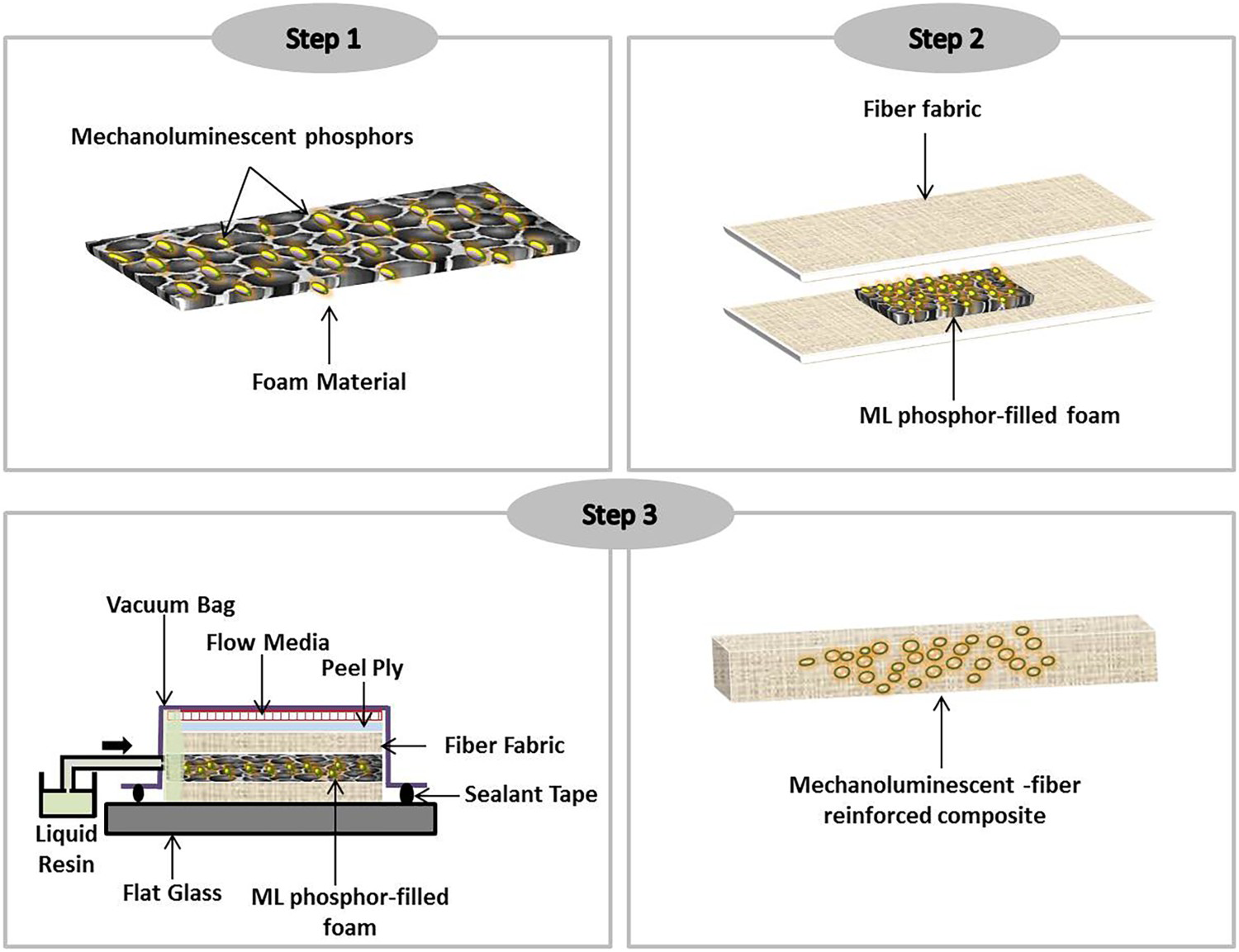
Herein, two varieties of ML phosphors were utilised in this study: highly ML europium dibenzoylmethide triethylammonium (EuD4TEA) phosphors and manganese-doped zinc sulphide (ZnS:Mn) phosphors. EuD4TEA and ZnS:Mn phosphors were integrated into glass fibre vinyl ester (VE) composites via the DFD technique to produce EuD4TEA-FRCs and ZnS:Mn-FRCs. Energy-dispersive spectroscopy (EDS) and scanning electron microscopy (SEM) were used to observe the spatial locations of EuD4TEA and ZnS:Mn phosphors, glass fibre and VE resin constituents. The effect of EuD4TEA and ZnS:Mn phosphor concentrations in PS foams on the short beam shear strength of DFD ML-FRCs was also investigated.
Materials and methods
Materials
Polystyrene pellets are purchased from Entec Polymers (USA). Highly mechanoluminescent ZnS:Mn phosphors are purchased from Phosphor Technology (UK). Europium dibenzoylmethide triethylammonium (EuD4TEA) was prepared in-house by methods outlined in [15]. N,N-dimethylformamide (DMF) and 2,2′-Azobis(2-methylpropionitrile) (AIBN) were purchased from Sigma-Aldrich. The reinforcements utilised are 2D woven glass fabrics purchased from Freeman Manufacturing & Supply Company. Armorstar IVEXC – 410 vinyl ester resin and methyl-ether ketone (MEKP) are purchased from Cook Composites & Polymer (CCP) and Norac Inc., respectively.
Fabrication of mechanoluminescent foams
The fabrication of ML foams involves a series of stages. Figure 2 depicts the stages involved in the fabrication of ML foams. Figure 2(a) depicts stage 1 of ML foam fabrication: ML phosphor-PS masterbatch synthesis. PS pellets are dissolved at 90 °C in DMF followed by the addition of ML phosphors (i.e. ZnS:Mn or EuD4TEA) in 2, 4, and 50wt-% concentrations. The weight percentages were chosen so as to capture the effect of higher and lower phosphor concentrations in PS foams.
Stages of ML foam fabrication (a) ML phosphor-PS masterbatch synthesis; (b) ML phosphor-PS taffy production; (c) foaming.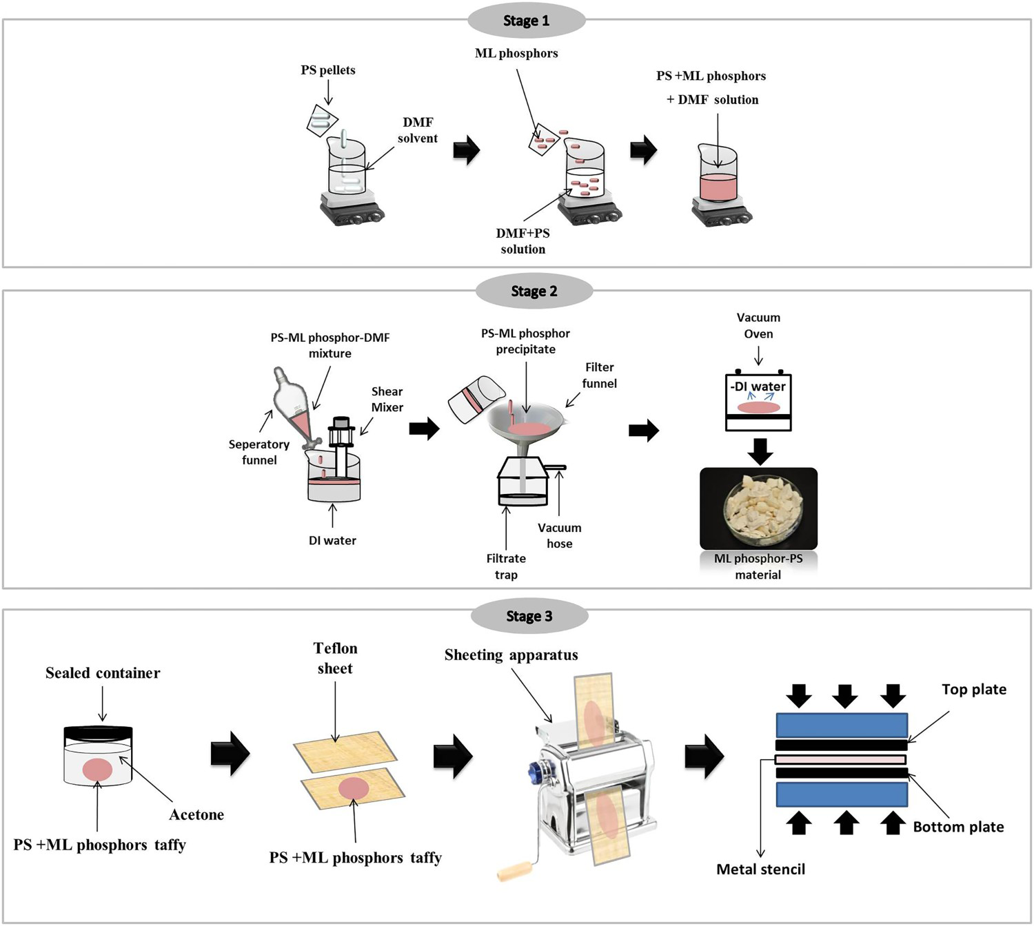
Figure 2(b) depicts Stage 2 of ML foam fabrication: ML phosphor-PS taffy production. The DMF-PS-ML phosphor solution is allowed to cool down and is added dropwise into a shear mixer containing deionised water. The volume ratio of DMF: water is 1:5. The solution is then filtered and dried into a chalky material. The total amount of chalky material is 5 g. The chalky material is re-dissolved at 90 °C in 50 mL of DMF, followed by the addition of 5wt-% 2,2′-Azobis(2-methylpropionitrile) (AIBN) foaming agent. The solution is left spinning for 24 hr. As the solution cools, the PS solidifies, trapping the suspended phosphors between the polymer chains and preventing phosphor sedimentation. This is meant to ensure good distribution of ML phosphors within the PS and therefore the final composite. The end result of stage 2 is a malleable taffy [16].
Figure 2(c) depicts Stage 3 of ML foam fabrication: foaming. The taffy is soaked in acetone for 24 h to allow for low temperature foaming. The taffy is then placed between two Teflon sheets and made flat via a sheeting apparatus. The sheeted material is then compressed via hydraulic press at 70 °C for 10 min. The applied heat decomposes the AIBN and releases nitrogen gas, resulting in a porous foam structure. The foam thickness is measured to be approximately 1.2 mm. Stages 1–3 were repeated to produce 0, 2, 4 and 50wt-% ML foams.
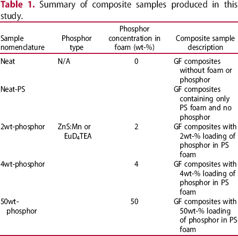
Summary of composite samples produced in this study.
ML composite fabrication
The ML phosphor foams cut into 1.0 × 1.0 cm sheets and placed in-between GF fabric layers during fibre-layup and infused with vinyl ester (VE) resin during standard VARTM processing. During VARTM, atmospheric pressure is used to inject resin into the GF reinforcement. The composites are then left to cure under atmospheric pressure for a period of 24hours before being de-moulded. Two types of control samples were fabricated: Neat samples were standard GF-VE composites without any foam or phosphor; Neat-PS samples were GF-VE composites with PS foam but without any phosphor. Table 1 summarises the types of composites produced in this study. Five samples of each type were tested. Following resin curing, the resultant ML-FRCs are cut by water-cooled diamond saw into rectangular beams and sanded into rectangular beams measuring 4.0 × 1.5 × 0.5 cm. Three layers of GF and two foam layers are used to manufacture each 2 mm short-beam shear sample.
Mechanical testing
The ML composites samples are tested in accordance with the ASTM D2344 standard for short-beam strength of polymer matrix composite materials and their laminates. A tabletop MTS Insight electromechanical testing system with a 1 kN load cell was used to apply and monitor force on as well as the resulting displacement of the samples. A span-to-depth ratio of 4 was chosen so as to permit shear failure [17].
Morphological characterisation
Sample preparation
ML-FRC samples were cut with a diamond saw to expose their cross-sectional areas. The samples were then coated with platinum via sputter coater for a period of 60 sec. The platinum coat helped to ensure adequate SEM imaging and EDS mapping.
Scanning electron microscopy
SEM microscopy was conducted using a JEOL SEM microscope. The microscope was set to an accelerating voltage of 20 kV and a working distance of 15 mm. EDS mapping was preformed using an EDAX system attached to the SEM microscope. The probe current for EDS mapping was set to 13µA. The total X-ray counts per pixel (cpp) were kept at a minimum of 200 cpp. The total map acquisition time was 1 h and 40 min.
Energy-dispersive spectroscopy
EDS mapping was conducted for the primary elements in each constituent of ML-FRCs was acquired. The constituents of ZnS:Mn-FRCs are glass fibre, VE resin, PS foam and ZnS:Mn. The GF constituent is composed of approximately 70% silicone and calcium elements [18]; therefore the elements chosen to map the spatial location of the GF constituent were silicon (Si) and calcium (Ca). Likewise, zinc (Zn) and sulphur (S) elements make up 95% of the ZnS:Mn constituent; therefore the elements chosen to map the spatial location of ZnS:Mn were Zn and S.
Results and discussion
Mechanical characterisation
Figure 3 depicts the short-beam shear (SBS) strength of ML-FRCs made with ZnS:Mn and EuD4TEA phosphors. Overall, the inclusion of neat PS foam and ML phosphor foams decreases the SBS strength of ML-FRCs. The greatest decrease in SBS strength is observed when comparing the Neat samples (i.e. a composite with no foam, no phosphors) to the Neat-PS samples (i.e. a composite with only PS foam, no phosphors) (see Table 1).
Short Beam Shear properties of (a) ML ZnS:Mn composites and (b) ML europium samples.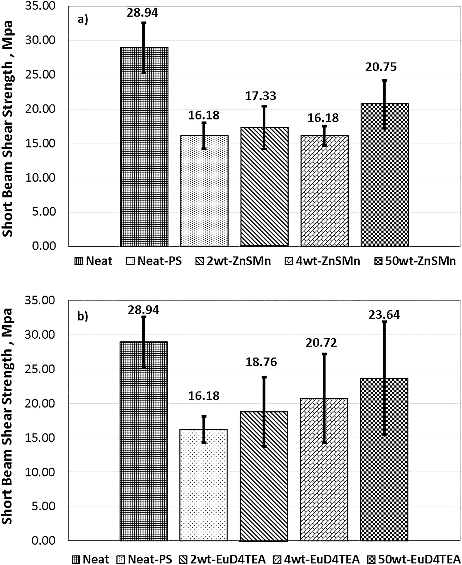
Summary of data collected for composite samples produced in this study.
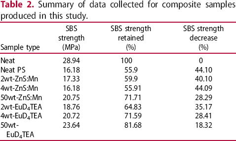
The prominent reduction of SBS strength for Neat-PS samples compared to the Neat composites is likely due to the presence of PS. PS is comparatively lower in strength than glass fibre and VE resin constituents, ∼70 MPa [19, 20]. The lower strength attributes of PS likely contributed significantly to the decrease of composite properties. This is observed in the drastic decrease in properties for the Neat-PS composites as compared to Neat composites.
The reduction of SBS strength for Neat-PS samples compared to the Neat composites could also be due to the blending kinetics of PS and vinyl ester resin during VARTM processing. During VARTM processing, the dissolution of PS by VE resin occurs through the absorption of VE molecules in-between the chain segments of PS. The PS chain segments begin to swell or increase in volume. Dissolution is completed when the polymer chains separate and disburse into the VE solution [21, 22]. Simultaneously, the styrene component in VE resin starts the curing process. During the curing processes, VE chains begin to crosslink until the resin gels and completely hardens.
In this instance, there are two processes taking place: PS dissolution and VE resin curing. The dissolution of polymers at room temperature is said to be a ‘slow moving’ endothermic reaction that requires time for the solvent molecules to separate and bind to the solute molecules [23]. However, the crosslinking of VE resin reduces molecule mobility. It is possible that the crosslinking of VE resin could have reached completion before the dissolution of PS in VE resin, freezing the system in a non-equilibrium state. In other words, it is possible that the absorption of VE molecules between PS chain segments occurs at a slower rate than VE resin crosslinking. This could have resulted in the incomplete VE-PS blending and a subsequent reduction of composite strength properties when comparing the Neat and Neat-PS.
In addition to this, Neat PS composites contain the highest concentration of PS. This indicates that there is also a higher concentration of PS to be dissolved by VE resin during VARTM processing. It is possible that Neat PS samples were not blended well as compared to samples with lower concentrations of PS and higher concentrations of ML phosphors i.e. samples containing 2, 4 and 50wt-% ML phosphors.
The highest percentage of shear strength retained was observed with the addition of 50wt-% EuD4TEA and 50wt-% ZnS:Mn phosphors. This could be due to a reinforcing effect of the phosphors. For example, during shear testing a shear force is applied causing sliding failure in the composites along a plane parallel to the shear force direction [24]. In this instance, the EuD4TEA and ZnS:Mn phosphors may have acted as shear pins that absorbed the shear load. A significant increase in phosphor concentration to 50wt-% may have provided additional pinning for more efficient shear reinforcement thus retaining higher shear strengths.
Additionally, composites containing EuD4TEA phosphors retained slightly higher SBS strengths than that of composites with ZnS:Mn phosphors. This is likely due to the difference in phosphor morphologies. For instance, ZnS:Mn phosphors are organic, smaller in size and softer in nature when compared to the inorganic, larger and harder EuD4TEA phosphors. Inorganic particles have been shown to have greater rigidities than organic particles [25]. It could be that loading was absorbed more efficiently by the larger more rigid EuD4TEA phosphors as compared to the smaller softer ZnS:Mn phosphors resulting in slightly better shear properties for EuD4TEA-FRCs.
Moreover, the morphological differences between ZnS:Mn and EuD4TEA phosphors could have resulted in differences at the VE resin-phosphor interface. For instance, in the case of thermosets toughened by rubber particles, the crosslinking of the thermoset within the rubber phase generates a high strength fibril formation that toughens the rubber and averts rubber particle fracture [26]. Similarly, the nature of the EuD4TEA-VE interface may have been more favourable than the ZnS:Mn-VE interface, resulting in higher SBS strength values.
Morphological characterisation
Scanning electron microscopy
The results of SEM microscopy are greyscale images of the sample's cross-sectional areas. The SEM microscopy yields the spatial location of VE and GF constituents in ML-FRCs made with ZnS:Mn and EuD4TEA phosphors. Figure 4(a-1) through Figure 4(d-1) depict SEM micrographs of 2wt-% ZnS:Mn, 50wt-% ZnS:Mn, 2wt-% EuD4TEA and 50wt-% EuD4TEA composite samples, respectively. The spatial location of the VE constituent for each sample type is identified by the darker regions (black circles) on the images (Figure 4(a-2) through Figure 4(d-2)). The spatial location of the GF constituent for each sample type is identified by the brighter granular areas (yellow circles) on the images (Figure 4(a-3) through Figure 4(d-3)). SEM microscopy does not yield the spatial location of the ZnS:Mn or EuD4TEA constituents.
SEM micrographs of ZnS:Mn and EuD4TEA FRCs cross-sections. (a) micrograph of 2wt-%-ZnS:Mn sample; (b) micrograph of 50wt-%- ZnS:Mn sample; (c) micrograph of 2wt-%- EuD4TEA sample; (d) micrograph of 50wt-%- EuD4TEA sample.
It can be observed that composites with larger concentrations of PS (2wt-%- EuD4TEA and 2wt-%-ZnS:Mn) have larger resin rich regions than composites with smaller concentrations of PS (50wt-%- EuD4TEA and 50wt-%-ZnS:Mn). It is feasible that samples with higher concentrations of PS added an extra degree of thickness to the FRC that resulted in a larger resin rich areas. These results could also highlight the need for the use of added pressure or compaction during the DFD technique to reduce resin regions and increase fibre volume fractions to improve the mechanical properties of ML-FRCs.
Yoon et al. [27] and Grant et al. [28] reported a reduction of resin rich regions and an increase in fibre concentrations for composites that underwent compaction treatments during VARTM processing compared to non-compacted composites. Additional compaction also yielded higher strength values. In this work, the 50wt-% EuD4TEA and 50wt-% ZnS:Mn samples have the highest SBS strength retained and best observed compaction (i.e. narrowest gaps between fibre layers). Further investigations could be aimed towards the effect of manufacturing aspects such as compaction treatments on the structure and resulting mechanical properties of ML-FRCs fabricated via DFD technique.
Energy-dispersive spectroscopy
For EDS mapping, ZnS:Mn-FRCs are subjected to the high energy beam of the SEM microscope. The electron beam charges the sample surface, with differences in energy according to sample material. Each element present on the sample surface has a unique energy difference allowing the elements on the sample surface to be identified and mapped. PS and VE resin are combined during the sample manufacturing process. Because both PS and VE consist of primarily carbon and hydrogen, PS and VE constituents were found to be indistinguishable via EDS mapping.
In addition to this, EDS maps were also overlaid onto the SEM micrographs to verify the spatial location of the constituents Figure 5 depict the EDS-SEM overlays for 2wt-% ZnS:Mn and 50wt-% ZnS:Mn composite samples, respectively. The EDS map does not cover the entire cross section image via SEM; the EDS trace's area is overlaid at the matching area on the SEM. The spatial locations of GF and ZnS:Mn are clearly identified via overlaid EDS mapping and SEM.
Overlaid EDS map and SEM micrographs of ZnS:Mn and EuD4TEA FRCs. (a) SEM-EDS overlay of 2wt-%-ZnS:Mn sample. Glass fibre constituent elements are blue and pink, respectively. Zinc and sulphur elements are yellow and light blue, respectively; (b) SEM-EDS overlay of 50wt-%-ZnS:Mn sample. Glass fibre constituent elements are yellow and light blue, respectively. Zinc and sulphur elements are blue and pink, respectively.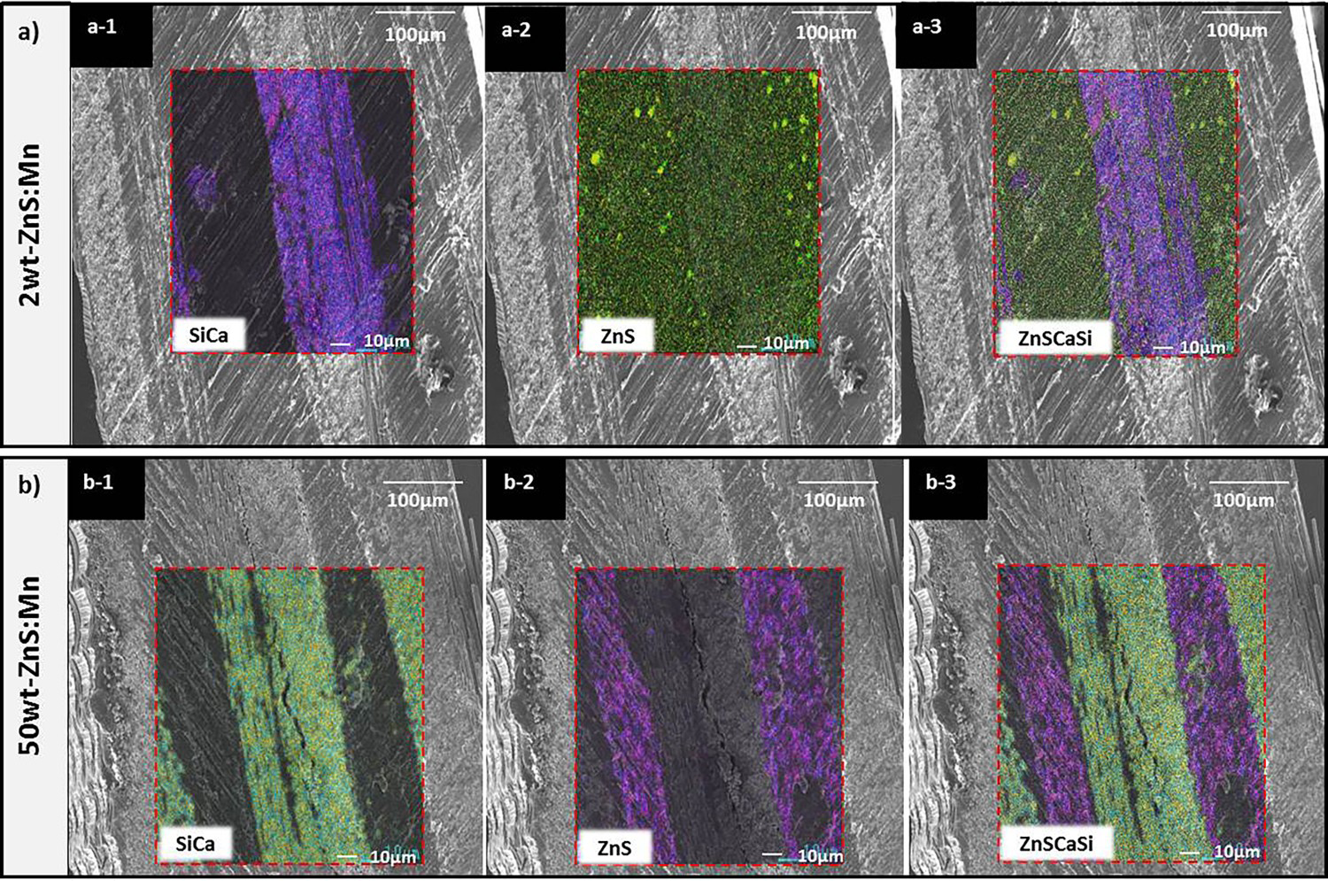
For the 2wt-% ZnS:Mn samples, the silicon and calcium elements in the GF constituent are marked by blue and pink pixels, respectively (Figure 5(a-1)). The EDS map corresponds well with the SEM micrographs in the identification of the spatial location of the GF constituent. The sulphur and zinc elements in the ZnS:Mn constituent are marked by yellow and green, respectively (Figure 5(a-2)). The ZnS:Mn constituent appears to be dispersed across the entire cross sectional area. Figure 5(a-3) shows the overlay of Figure 5(a-1) and Figure 5(a-2) and the SEM micrograph.
Figure 5(b-1) depicts the EDS trace of the GF constituent in the 50wt-% ZnS:Mn sample. Unfortunately, the EDS would not allow for parallel pixel colours for constituents. Therefore, in this instance, the EDS map identifies the spatial location of the silicon and calcium elements in GF as yellow and green pixels, respectively, and sulphur and zinc elements in the ZnS:Mn as pink and blue pixels, respectively (Figure 5(b-2)). As in the previous case, the EDS map corresponds well with the SEM micrographs in the identification of the spatial location of the GF constituent. Figure 5(b-3) shows the overlay of Figure 5(b-1) and Figure 5(b-2). Contrary, to the 2wt-% ZnS:Mn sample, the ZnS:Mn constituent appears to be located in-between the glass fibres, within the VE-rich region.
Since the intended usage of ML phosphors is for sensory applications, the ability to control the spatial location of the sensory material in the composite material (e.g. by using ML foams) is a valuable feature. For example, one of the critical safety concerns in the aerospace industry is the vulnerability and damage tolerance of aircrafts to impacts such as birds, metal fragments and hail [29-31]. Such low velocity impacts are barely visible in FRCs and can cause internal matrix cracking, delamination and broken fibres. In instances like these, the ability to selectively place ML phosphors within the composite aircraft components as needed would allow for the advanced utilisation of FRCs as both load bearing and functional components in aircraft structures. Similarly, strengthening material such as carbon nanotubes nano-clay, carbon black etc. could also be selectively placed in composites via the DFD technique.
Control of the spatial location of the sensory material containing lower ML phosphor loadings may not allow for such selective placement as they were seen to disperse over the entire composite cross sectional area (e.g. the EDS maps of the 2wt-ZnS:Mn sample, Figure 5(a-2)). However, EDS maps of composite samples containing lower loadings of constituents like ML phosphors have been shown to exhibit a low concentration effect in which the EDS mapping is less accurate in determining the spatial location of the elements present [32, 33]. Control of the spatial location of the sensory material containing higher ML phosphor loadings does allows for such selective placement (e.g. the EDS maps of the 50wt-ZnS:Mn sample, Figure 5(b-3)). In any case, EDS mapping proved a useful qualitative tool for the mapping of ML-FRC constituents.
Conclusions
In conclusion, the short beam shear properties of mechanoluminescent-fibre reinforced composites manufactured via the displaced foam dispersion technique are reported. Lower short beam shear strength values are observed for fibre-reinforced composites containing mechanoluminescent foams and polystyrene foams. Such decreases are attributed to the concentration of PS, mechanoluminescent phosphor inclusions and interactions between vinyl ester resin and mechanoluminescent-phosphors and the compaction of the fibre layers during VARTM processing. The addition of polystyrene foam lowers the short beam shear strength more than mechanoluminescent phosphor foams. Lower polystyrene concentrations had higher short beam shear strength. These samples also had a greater degree of compaction of the glass fibre layers. The decreases in short beam strength due to the loading of inclusions into fibre reinforced composites is expected and reported elsewhere for composite systems loaded with inclusions.
Mechanoluminescent-fibre-reinforced composites manufactured via the displaced foam dispersion technique are also characterised. Scanning electron microscopy and energy-dispersive scanning revealed the selective placement of mechanoluminescent phosphors between glass fibre layers. The selective placement feature provided by the displaced foam dispersion technique could be used to tailor or customise fibre-reinforced composites with multiple inclusion types.
Over all, the observations made revealed important variables to consider for the development of the displaced foam dispersion technique. To minimise the effect of inclusions, future work will involve studies to understand and optimise the kinetics of simultaneous vinyl ester resin curing and mechanoluminescent phosphor foam dissolution, polystyrene concentrations in mechanoluminescent-fibre-reinforced composites and the effect of compaction treatments on the mechanical behaviour of mechanoluminescent-fibre-reinforced composites manufactured via the displaced foam dispersion technique. In addition to this, mechanoluminescent-fibre-reinforced composites will be evaluated under a broad spectrum of loading conditions such as tensile, flexural and impact loading to create a performance index for these materials for their potential use in the in-situ monitoring of fibre-reinforced composites.
Footnotes
Acknowledgements
The authors would like to acknowledge Kendall Parker at the Florida A & M University for her assistance with sample preparation. Thank you also to Emily Hammel, Dr. Tarik Dickens and Chukwuzubelu Ufodike for their support and assistance.
Disclosure statement
No potential conflict of interest was reported by the authors.