
Abstract
To extend the diversity of commercial materials relevant for fused filament fabrication (FFF), the relation of nozzle temperature and layer thickness with respect to final product mechanical performance is examined for the less studied group of (co)polyesters, considering tensile and impact strength and microscopic imaging. It is demonstrated that with limited polymer degradation, one can focus on increasing the layer height (from 0.1 to 0.3 mm) by tuning of the contribution of inter-layer welding, whereas with significant degradation, a lower layer height (0.1 mm) is needed to exploit the contribution of intra-layer welding for which a higher nozzle temperature (e.g. 260°C) is beneficial. The relevance of degradation is studied by both melt flow index and rheological analysis. The study ultimately provides the best FFF parameters for three commercial copolyesters and highlights the competition of inter- and intra-welding as a key microscopic material design strategy.
Keywords
Introduction
Fused filament fabrication (FFF) is one of the most popular additive manufacturing (AM) methods and is applicable in many fields of modern product development [1-5]. This technique gains popularity due to its short cycle time, dimensional accuracy, user friendliness and elegant connection with computer-aided design (CAD) software [6]. However, material limitation is an aspect which restricts FFF product development [7]. Currently, only acrylonitrile-butadiene–styrene polymer (ABS), poly(lactic acid) (PLA), and a small amount of other polymers can be widely used, which does not meet the diversity demanded by the polymer processing industry regarding full exploitation.
It has been indicated that the manufacturing parameters have a great impact on the final properties [8, 9]. Numerous tests have been performed to find the relation between the print parameters and the mechanical properties of specimens manufactured in commonly used FFF materials such as ABS and PLA. For example, Ahn et al. proved that for ABS a higher nozzle temperature causes a small but statistically significant increase of the mechanical properties [10]. Similar results for ABS were achieved by Ziemian et al. with a higher nozzle temperature creating a better layer adhesion [11]. The layer adhesion has also been called the weld strength and is defined by the thickness and the amount of polymer entanglement [12]. Wang et al. found that for PLA a too low nozzle temperature results in a deteriorated fusing behaviour linkable to the melt flow index (MFI) value, which may not be lower than ca. 10 g min–1 (200–230°C) [13]. In follow up work [14], the usefulness of annealing and the addition of poly(3-hydroxybutyrate) to control crystallinity has been demonstrated. Furthermore, Rankouhi et al. put forward that ABS parts with a layer thickness of 0.2 mm show higher stiffness than those printed with a layer thickness of 0.4 mm [15]. Gurrala and Regalla suggest that for ABS a balance between the effect of layer thickness on the layer adhesion and density must be found, since thicker layers preserve heat better inducing better adhesion, but also cause a larger surface area of each deposited filament, creating larger voids between them [16]. Alafaghani et al., however, found that for PLA specimens, the mechanical properties improve with higher layer thickness [17].
A further investigation is thus relevant specifically if one focuses on other polymer materials than PLA and ABS. In the present work, we study FFF of recently developed commercial (co)polyesters. These materials have been printed using three nozzle temperatures and three layer heights. It is shown that a higher nozzle temperature results in improved properties but the effect of layer height is complex. Here, the degradation effect needs to be taken into account.
Materials and methods
Materials
Commercial copolyesters were kindly provided by Eastman as pellets. They have as specific grade names: AM3300, AM1800 and HT5300 but will further be called CP-IPA, CP-CH and CP-HT. CP-IPA is a copolyester considering isophthalic acid (IPA) and cyclohexane dimethanol (CHDM) comonomers. CP-CH only has a small CHDM modification. CP-HT is mainly characterised by a modification with tetramethyl cyclobutanediol. As will be illustrated further these materials have a similar MFI value.
Methods
The processing steps are represented in Figure 1, with extrusion (1) of copolyester pellets (2) to filament (3) and subsequent FFF (4) to manufacture the test bars (5), differentiating between analysis pathways, including mechanical and morphological analysis. Since degradation is likely to occur, the MFI of the materials after each step has been additionally monitored. Since the MFI of one material increased significantly more than the other materials after FFF, its degradation was studied more in depth using parallel plate rheometry as well. All data has been analysed using a statistical significance level of 0.05.
Processing steps and the subsequent analysis pathways.
Extrusion of filaments
Processing parameters of the copolyester extrusion.
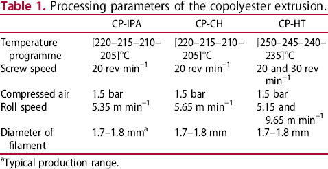
Typical production range.
Fused filament fabrication
All test specimens have been manufactured using PRUSA i3 MK3 printers with a 0.4 mm nozzle. The printhead covers all x- and z-movements while the bed moves in the y-direction. A schematic representation is shown in Figure 2. The filament (1) is fed to the printhead using a roller system (2). Then it is led to a heated chamber (3) where the polymer is molten to the desired temperature as it moves towards the nozzle (4). Subsequently, the material is continuously pushed through the nozzle and deposited onto the heated print bed or already printed substrate (5). The printing parameters are given in Table 2.
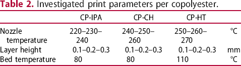
Working principle of a fused filament fabrication printer with (1) filament, (2) roller system, (3) heated chamber, (4) Nozzle and (5) print platform. Investigated print parameters per copolyester.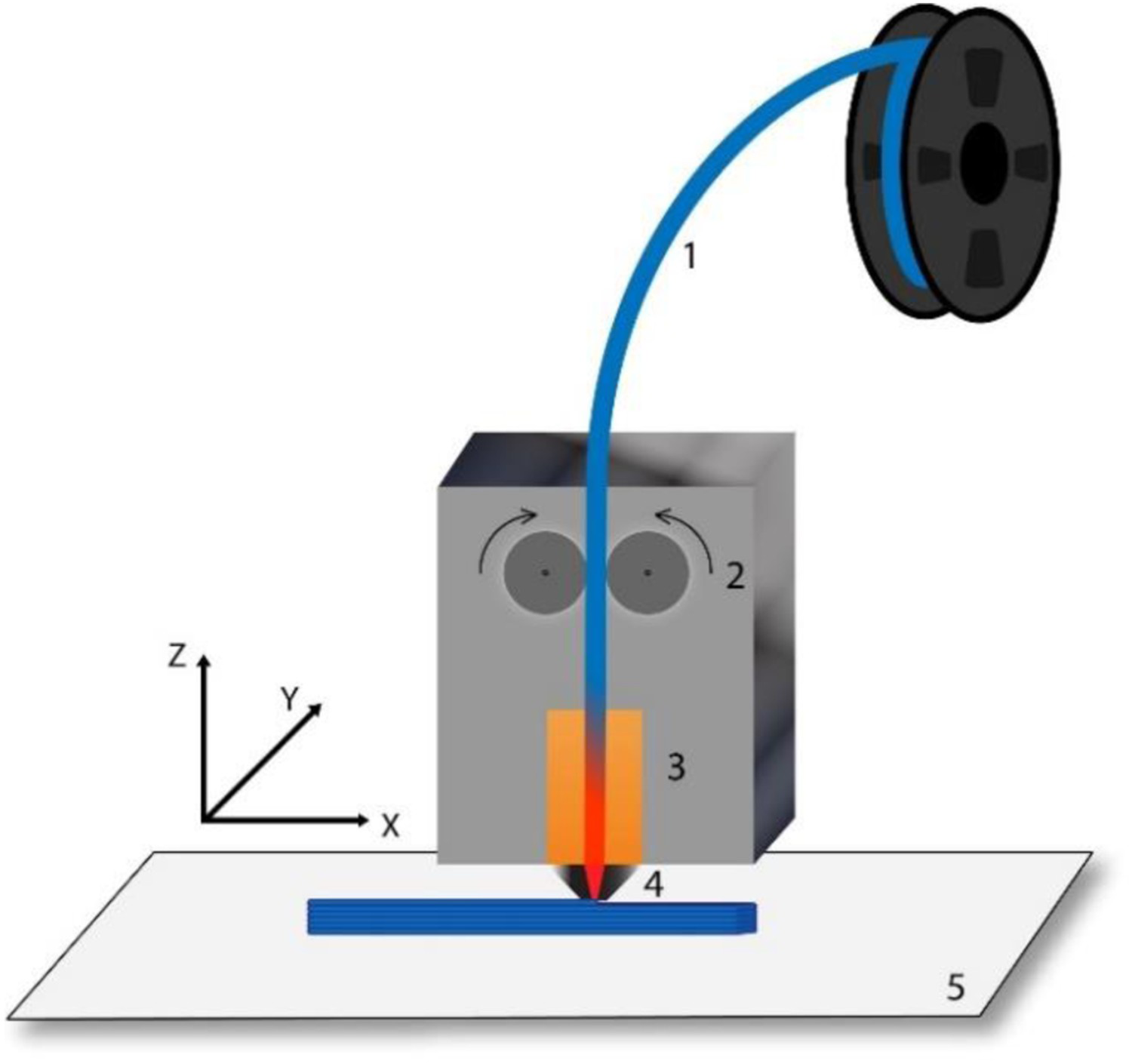
In what follows, T low, T middle and T high are the lowest, middle and highest nozzle temperatures of each copolyester for FFF. Aside from the nozzle temperature and layer height, all other print settings were maintained constant for the production of all discussed test specimens. To achieve the most representative values of mechanical properties, all samples were printed with 100% fill density in a rectilinear pattern (−45°/+45°) with a constant bed temperature [18]. The spacing between bonded linear depositions was generated by the Prusa Slicer software which defined a thickness of 0.45 mm for the deposited roads in the infill structure for all produced specimens, next to an average distance of 0.680 mm between the centre points of two adjacent deposited roads. These values were checked in the tool-path generated by the slicing software. If not mentioned otherwise a default printing velocity of 20 mm s–1 for the solid infill and 60 mm s–1 for the perimeters have been employed.
Melt flow index and rheological characterisation
MFI was measured according to the ISO-DIS 1133-1 standard with a weight of 2.16 kg on a Davenport MFI10 device. The T middle value is used as a barrel temperature.
Small amplitude oscillatory shear (SAOS) tests were performed using a MCR 702 rheometer (Anton Paar, Austria). Storage modulus (G′) and loss modulus (G″) were monitored as a function of frequency (600 to 0.1 rad s−1) using the parallel plate configuration with a 25 mm diameter, gap of 1 mm and amplitude of 1%. The tests were carried out under nitrogen atmosphere at 190°C. The dried pellets, shredded filament and shredded printed parts were compression moulded at 180°C into 1 mm thick discs, with a 25 mm diameter. The discs were dried before the rheological measurements.
Mechanical testing and imaging
The tensile strength was evaluated by a tensile test on an Instron5565 machine according to ISO 527, performed on ISO 527 1BA samples. The tensile strength was determined as yield at zero slope using Bluehill 2 software. Furthermore, toughness was measured as the impact energy in a notched Charpy impact test on a Tinius Olsen IT 503 following ISO 179.
The microscopic images were collected with a Keyence VHX-500FE Digital microscope. The fracture surfaces of three cryogenic broken impact bars per material have been investigated. The samples were first cooled in liquid nitrogen for five minutes and then broken in two pieces using a Tinius Olsen impact tester. For each setting, at least three microscopic images which contained five or more useable weld length values have been investigated.
Results
The relevance of degradation
During the extrusion and FFF step in Figure 1 degradation might occur due to hydrolysis (if e.g. water/moisture is present) [19, 20], too high temperatures leading to undesired side (e.g. fission/scission) reactions [21] and too high shear rates (breakage due to mechanical forces). This was monitored by checking the MFI behaviour of the pellets and comparing it with the MFI behaviour of the extruded filaments and the parts printed at the three nozzle temperatures. If a significant increase in MFI is noted, degradation is likely to have occurred. Figure 3 displays MFI-values of the materials as pellet, filament and printed with lowest (T low), intermediate (T middle) and highest nozzle temperature (T high).
MFI as a function of material morphology.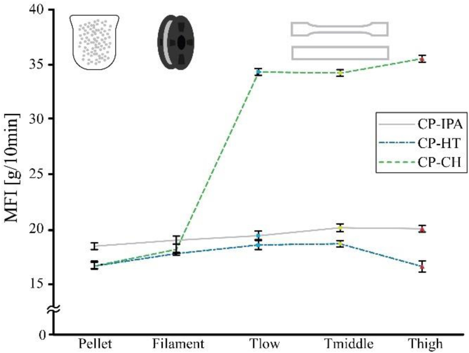
The MFI always has a slight increase upon switching from pellet to filament, indicating a small amount of degradation during extrusion. After FFF, the flow behaviour of each material changed in a different manner. CP-CH is the most prone to degradation during FFF while the other two copolyesters only have a small increase in MFI values. CP-HT has however an unexpected drop in MFI value at T high, indicative of a first sight undesired chemical modification, e.g. crosslinking or the formation of a cyclic bond [22]. The overall small change of MFI-values makes it possible to assume that degradation during FFF should barely influence the properties of the parts printed with CP-IPA and CP-HT while material properties of CP-CH could be altered significantly.
The strong degradation of CP-CH during FFF has been investigated more deeply by carrying out SAOS tests. Again tests were performed on CP-CH pellets, filament and FFF specimens. To designate whether temperature or shear is the most prominent factor that causes CP-CH degradation during FFF both a high (290°C) and low (220°C) nozzle temperature were used in combination with a variation of the setting printing velocity, so from default (100%) to 50% (V low) and 200% (V high).
Figure 4(a) exhibits the corresponding (complex) viscosity curves. After each processing step, CP-CH shows a reduction in its viscosity over the entire range of frequencies. Similar to the results of the MFI measurements, the pellets exhibited the highest viscosity, followed by the filaments and then the printed parts, representing a reduction in average molar mass after every processing step. The FFF conditions play an important role in the degradation of CP-CH. If higher printing temperatures are employed, the decrease in viscosity is more pronounced, suggesting that the degradation is more severe and leads to a greater reduction of the CP-CH average molar mass. For a low printing velocity also a stronger degradation results, which may be related to a higher residence time of the material in the extruder, in which the material is exposed to heat for a longer time.
(a) Complex viscosity variation for CP-CH, including different processing conditions; insert zoom-in the small frequency region; (b) Variation of G′ and G″; insert zoom-in the crossover.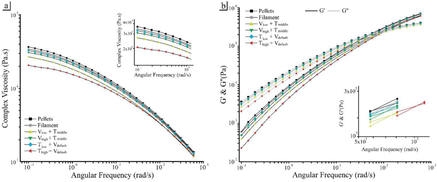
Frequency of crossover obtained from G′ and G″ curves in Figure 4(b).

Evaluation of the material performance
Results for the tensile strength (thus maximal stress) of samples printed with a layer thickness of 0.2 mm can be found in Figure 5 (bars). A higher nozzle temperature (left vs right bar per material) generally has a positive effect on the (tensile) strength of the specimens. For CP-IPA, CP-HT and CP-CH the strength increases by 3.2%, 14.5% and 4.9%, respectively, comparing the lowest print temperature with the highest. An explanation is the different adhesion between the deposited filaments and layers, also called the intra-layer and inter-layer welds. The properties at the filament interfaces are inferior to those of the bulk material [9]. Better welds between the deposited strands of material, or so-called roads, result in better properties. In previous research by McIlroy et al. improvement of the inter-layer welds has been directly related to interdiffusion and entanglement of the polymer melt across the interface [12, 24]. For layers printed at higher temperatures, the diffusion has been noted less restricted consistent with diffusion theories [25], creating a stronger inter-layer weld.
Values of tensile strength and impact energy of the test bars printed at the lowest (for CP-IPA, CP-HT and CP-CH, respectively, 220, 250 and 240°C) and highest nozzle temperature (for CP-IPA, CP-HT and CP-CH, respectively, 240, 270 and 260°C); fixed layer height of 0.2 mm.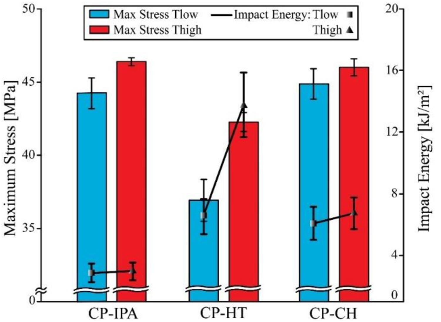
Figure 5 additionally displays (points) that CP-HT has a great improvement of toughness, since it nearly doubles with an increasing nozzle temperature from 250 to 270°C. This further confirms that also the chemical modification at the highest temperature in Figure 3 (slight drop of MFI) is significant. For the other two materials, no significant differences in toughness can be found. Hence, the exposed degradation for CP-CH has no genuine effect on the macroscopic properties in Figure 5, at least at the selected layer thickness. The chains are still long enough and interacting sufficiently to enable strength and impact [26], the latter specifically at higher temperature.
The variation in tensile strength of the samples printed at T high with different layer heights is represented in Figure 6. Before the layer height was 0.2 mm and now also values of 0.1 and 0.3 mm are included. For CP-IPA and CP-HT, the strength improves with respectively 8.0 and 14.6% for an increasing layer height while copolyester CP-CH reacts in the opposite manner and reduces by 12.7% in tensile strength. Bellehumeur et al. recorded for ABS a beneficial effect of the temperature on the thickness of the intra-layer welds [27]. However, the results in Figure 6 indicate that strong degradation (CP-CH case) complicates the efficient realisation of a larger layer thickness.
The tensile strength, represented by the maximal stress, of the printed tensile bars as a function of their layer thickness printed at the highest temperature.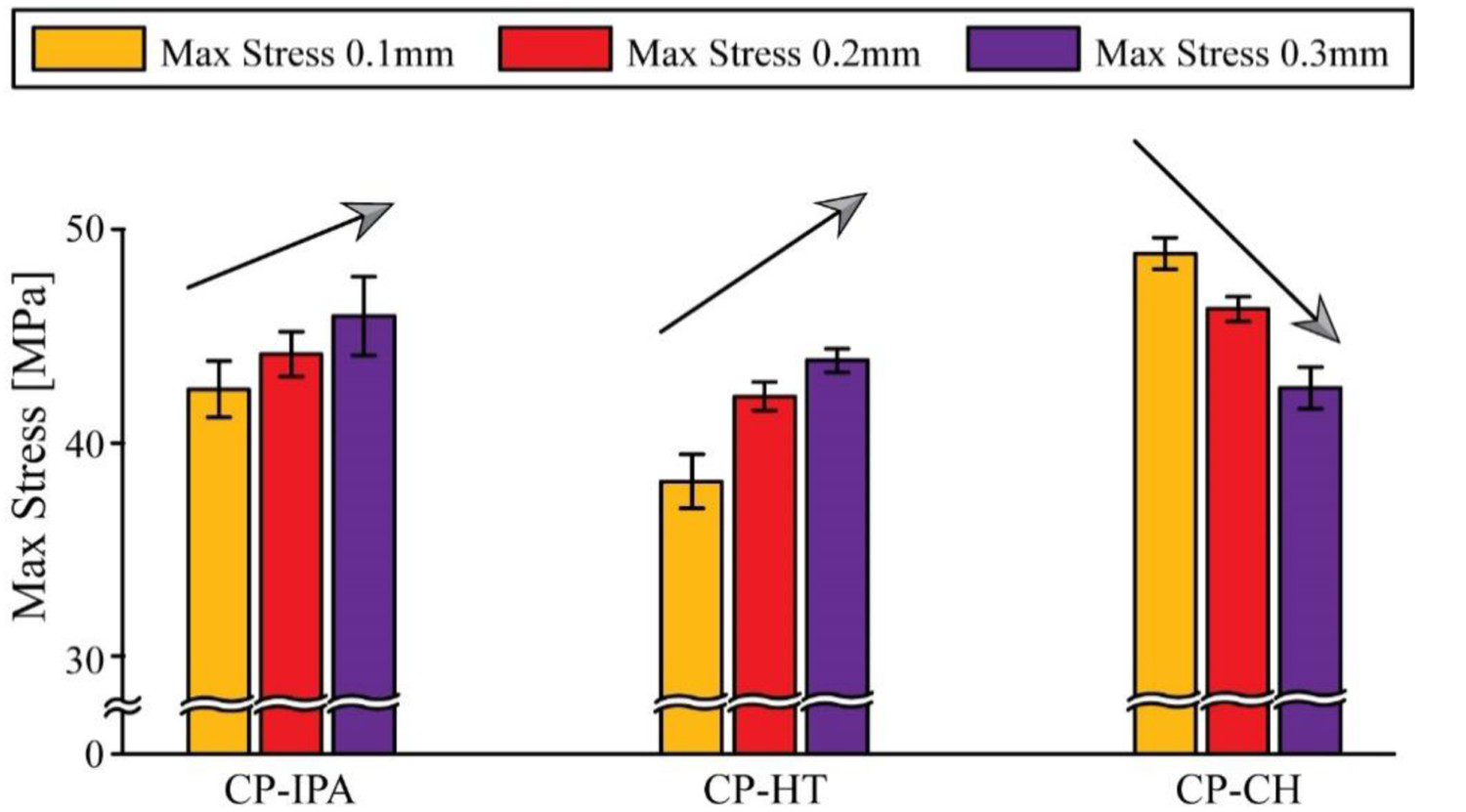
Morphological analysis
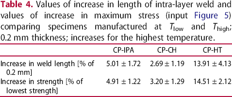
To achieve a better understanding on how the FFF parameters affect the welds and how these welds on their turn affect the mechanical properties (cf. results in Figures 5 and 6), the morphology of the printed parts has been investigated using microscopical analysis. For the three copolyesters, the inter- and intra-layer welds have been visualised for parts printed with T low and T high as nozzle temperature and first with a layer thickness of 0.2 mm. Since the behaviour of the three copolyesters upon a temperature increase is comparable to a first approximation (cf. Figure 5), only the microscopic images of CP-IPA are displayed in Figure 7.
Welds between printed filaments of CP-IPA at T low and T high. Derived data in Table 4.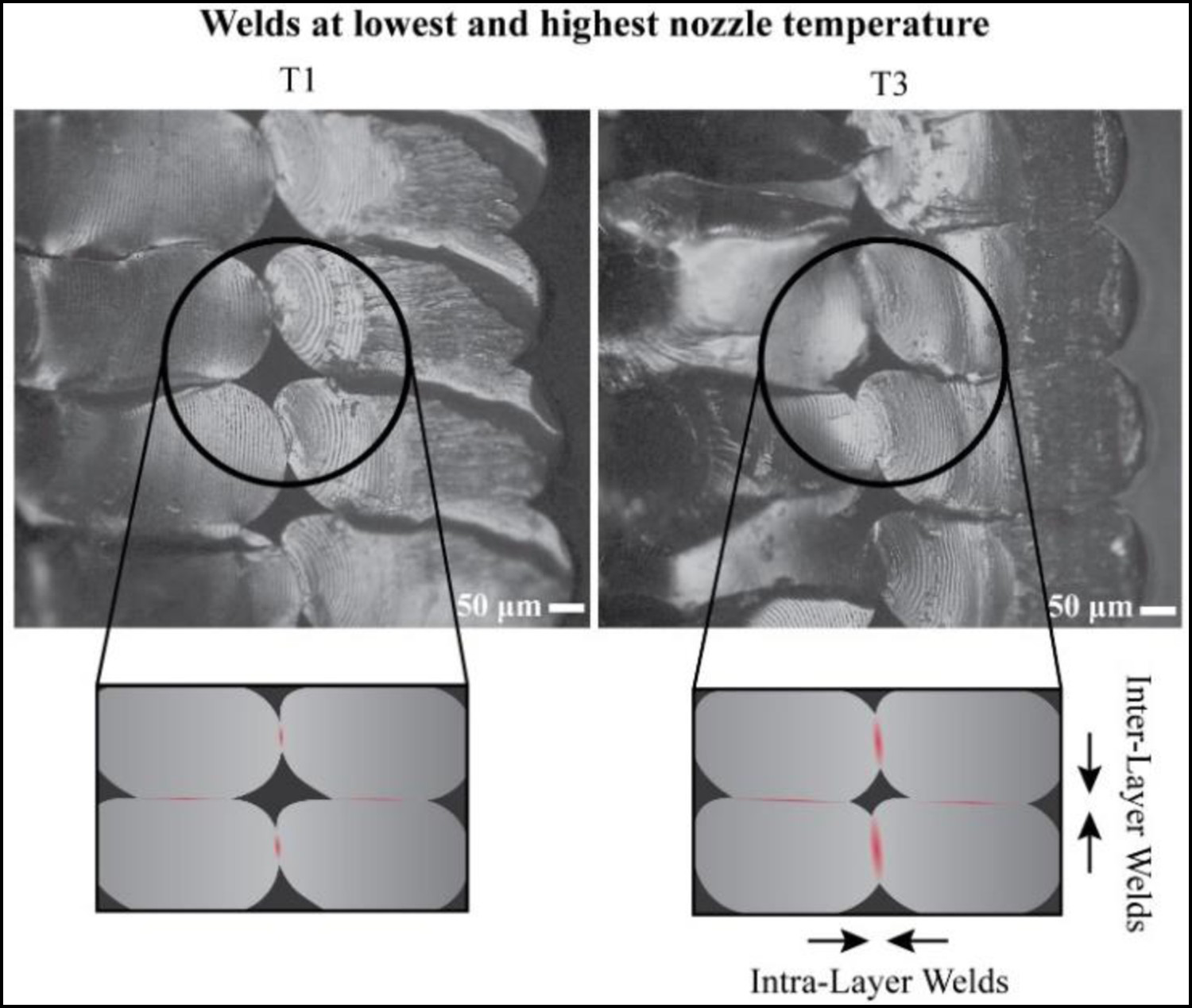
Values of increase in length of intra-layer weld and values of increase in maximum stress (input Figure 5) comparing specimens manufactured at T low and T high; 0.2 mm thickness; increases for the highest temperature.
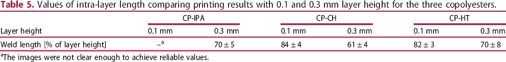
In Figure 8, the effect of the layer height on the microscopic structure of the printed parts has been visualised, considering CP-CH and CP-HT, thus covering both effects from Figure 6 (decrease and increase). For samples which have been manufactured with a layer height of 0.1 mm, the welds appear in both cases larger and the voids smaller. By measuring the length of the intra-layer welds and comparing them with the layer height the percentual values in Table 5 result. The percentual intra-layer weld length is lower for parts printed with a layer thickness of 0.3 mm which cannot explain the improved mechanical behaviour of CP-IPA and CP-HT in Figure 6.
Welds between printed filaments of CP-CH and CP-HT printed with a layer height of 0.1 and 0.3 mm. Values of intra-layer length comparing printing results with 0.1 and 0.3 mm layer height for the three copolyesters. The images were not clear enough to achieve reliable values.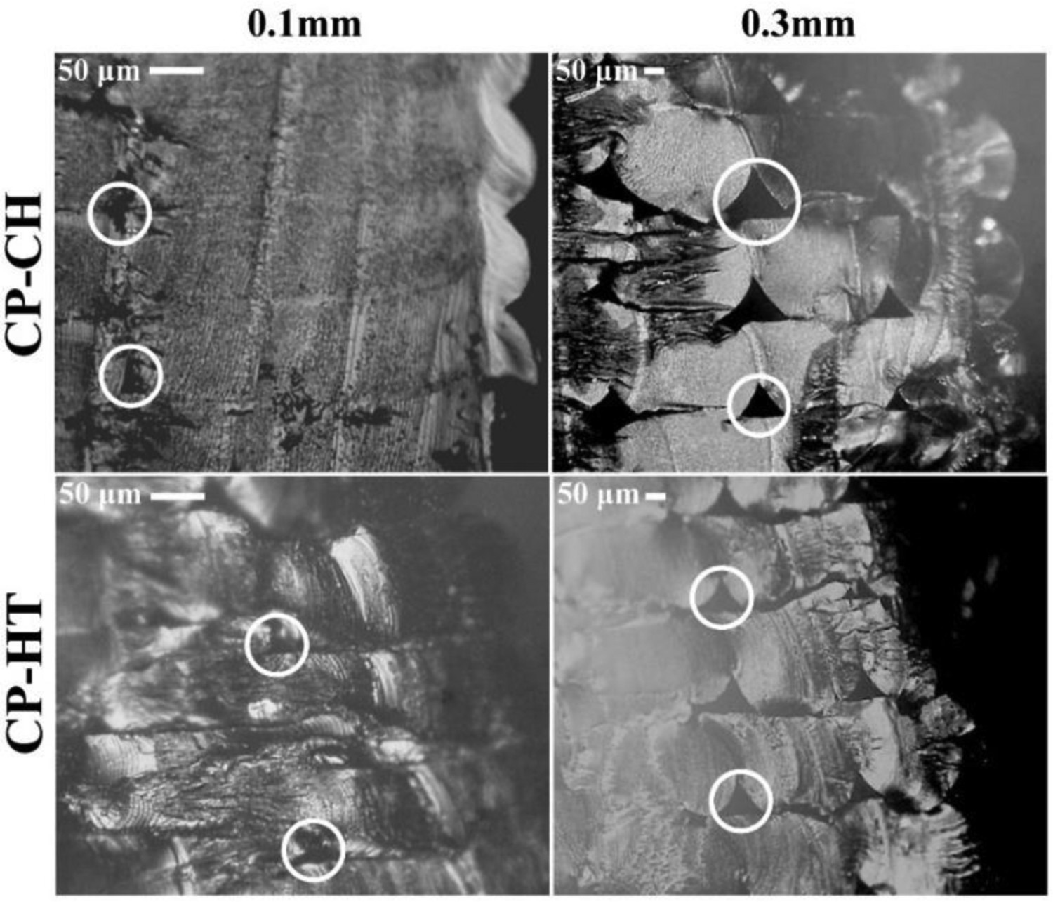
It can be presumed that the relevance of the strength of the inter-layer welds is more pronounced for these copolyesters at higher layer thicknesses. Since the thicker layers preserve heat better [28], the high temperature is maintained for a longer time. This results in the presence of more energy for diffusion to create a better bonding quality between the layers in the form of a thicker and more entangled weld [12]. However, the larger circumference of the roads cause larger voids between the filaments at the locations where the weld is not formed [12]. The improved diffusion in the welds compensates this and results into an increasing tensile strength measured with a 45° angle towards the rectilinear road pattern for CP-IPA and CP-HT parts. Indeed, from the fracture behaviour of the 0.1 mm printed specimens, it can be presumed that the inter-layer adhesion is poor since every layer has broken at a different height.
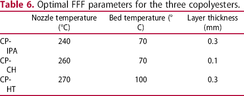
Optimal FFF parameters for the three copolyesters.
Conclusions
The mechanical, rheological and morphological properties of three commercial FFF copolyesters have been examined and compared by altering the nozzle temperature and layer height. At a given layer thickness, a higher nozzle temperature improves the mechanical properties, which can be associated with an improved intra-layer adhesion. An increasing layer thickness will lead to improved properties due to increased interlayer interaction only if one has limited degradation. This is the case for CP-IPA and CP-HT but not for CP-CH. For this last copolyester the MFI of the printed parts nearly doubles compared to the value for the pellets and filaments, with SAOS tests showing that CP-CH is mainly prone to temperature-related degradation.
Footnotes
Acknowledgements
The authors would like to thank Eastman Company for providing the materials. S.W. gratefully thanks for the financial support from China Sponsorship Council (CSC).
Disclosure statement
No potential conflict of interest was reported by the author(s).