
Abstract
The revised abstract is as follows:As a new waterproof system with plastic in underground silos, three kinds of polypropylene plastic welds were designed and subjected to a water-pressure resistance test in pump-pressure mode. The failure modes, stress processes, failure mechanisms, and influencing factors of different weld forms with different thicknesses were studied. The water-pressure resistance on the groove-weld specimens with welded cover plates was increased by approximately 40%–85% compared with that of the groove-weld specimens. The water-pressure resistance for groove-weld specimens with pasted and welded cover plates was increased by approximately 10% compared with that of the groove-weld specimens with welded cover plates. The depth of the designed underground silos is generally lower than 35 m, and the 8-mm plate thickness and groove-weld specimens with welded cover plate combination can resist 58.16 m of water pressure with a recommended safety factor of 1.66.
Introduction
Land resources on the ground are becoming scarce, and land use can be reduced through underground spaces [1]. However, waterproofing and moisture-proofing are problems restricting the development of underground storage structures [2]. Waterproof methods commonly used in underground structures include coil, coating, and steel plate waterproofing [3-5]. Bonding the overlapping parts of waterproof coiled materials is difficult, and the coiled materials are easily damaged. Waterproof coating requires to be applied at intervals, and the quality is difficult to control. Some coatings also are toxic and cannot be directly contacted with edible substances. A steel plate is effective for waterproofing and difficult to break. However, the contact between the steel plate and water easily rusts, restricting the application of steel plates as waterproof layers [6-8]. Plastic materials are light and corrosion resistant, with low thermal conductivity, heat preservation, waterproofing and energy saving capabilities, and convenient processing and formation [9]. They also have a high recovery efficiency and can be used as waterproofing systems in underground structures.
Chen et al. [5] proposed the application of a plastic sandwich plate in underground waterproof engineering. Xie et al. [10] introduced a waterproof and drainage system and construction technology for plastic plates in tunnels. Yang et al. [11] used a plastic plate and other waterproof materials to select and design waterproof structures for seepage prevention and leakage repair. Among them, polyethylene plastic waterproof board materials are widely available, are simple to construct, and achieve good waterproofing and anti-corrosion performances, without poisoning the environment. They have been adopted in Europe, Japan, domestic railways, and highway tunnels [10]. For the connection between polypropylene plastic plates, welding has become the preferred processing method for thermoplastic parts [12] and has been widely used.
There are relatively few direct results on the weld joints of waterproof plastic plates. Considering that a plastic weld is similar to a steel weld in form and stress characteristics, the latter is used as a reference in the design of plastic welds. For steel welds, Zhang et al. [13] believed that V-groove processing is simple and time- and labor-saving. Based on the standard V weld, Sui et al. [14] studied the design of different welding groove forms and weld process tests. However, the improved weld forms were mainly suitable for thick wall welds. Li et al. [15] studied the joint forms added to the middle backing and bottom cover plates at the groove root and indicated key points that should be considered during the welding process. Wang et al. [16, 17] conducted a joint test and finite element analysis at the lower part of the butt weld, showing that an increased thickness of the lining plate and adoption of the surrounding weld on four sides of the lining plate protects the welding seam area.
Because of the different material properties of plastic and steel welds, and waterproof plastic plates connected with welds mainly bear the effect of water pressure in practical applications, these studies have little guiding significance for the practical application of plastic welds in underground engineering. Hydraulic tests on the weld of polypropylene plastic plates are, therefore, necessary. Based on the engineering background of an underground granary in Zhongmou, China, and considering the characteristics of the plastic plate itself, three forms and three thicknesses of plastic welds were proposed and tested using the water pressure, failure mode, stress process, and failure mechanism of plastic plates, and the influencing factors of the weld strength were analysed.
Test overview
Specimen design and production
A total of 18 specimens were designed, mainly composed of a concrete block, polypropylene plastic plate, and water injection pipe. The concrete block and polypropylene plastic plate were glued together using a two-component silicone structural adhesive. A schematic of the specimen is shown in Figure 1.
Schematic diagram of polypropylene weld specimens.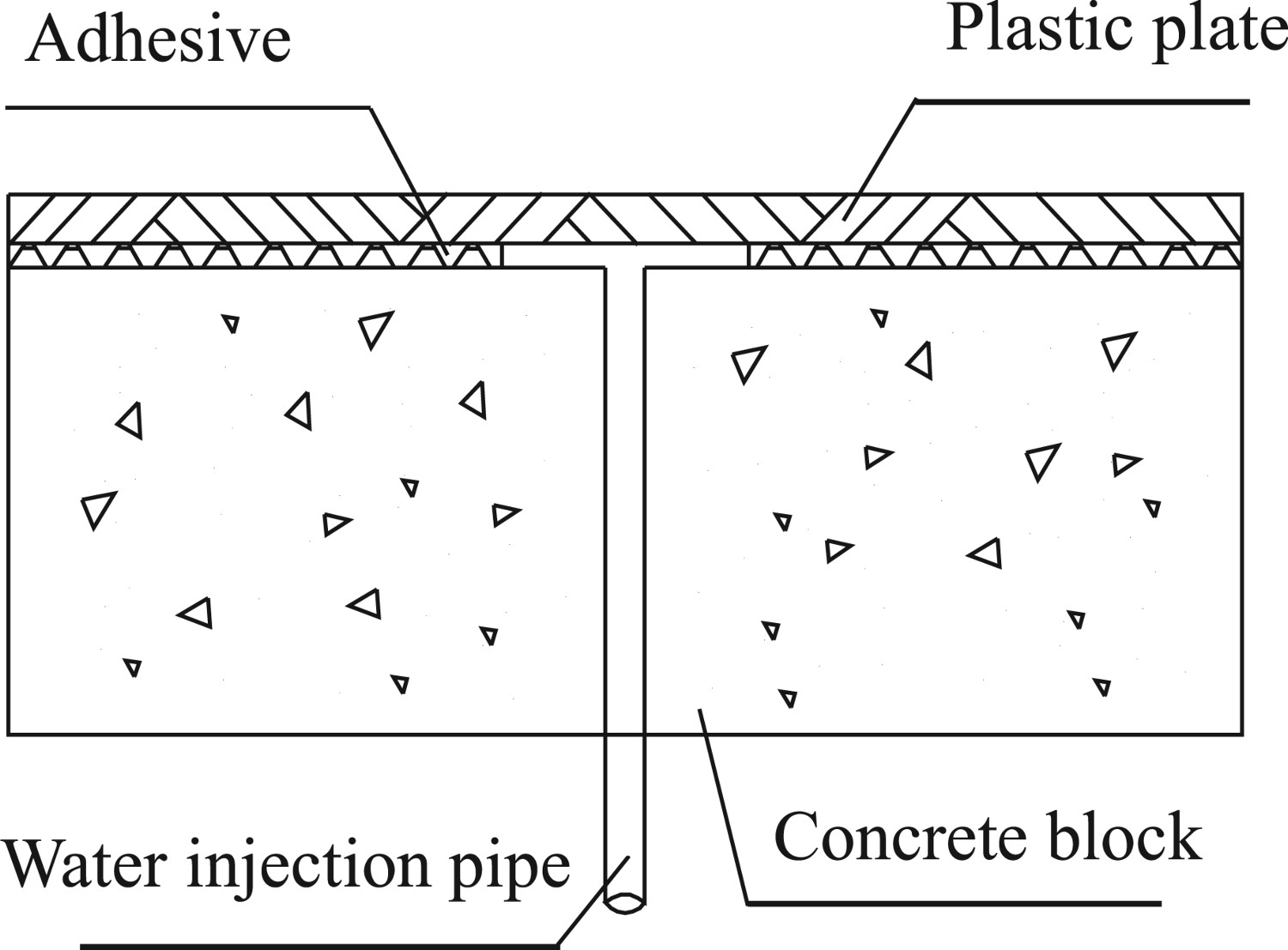
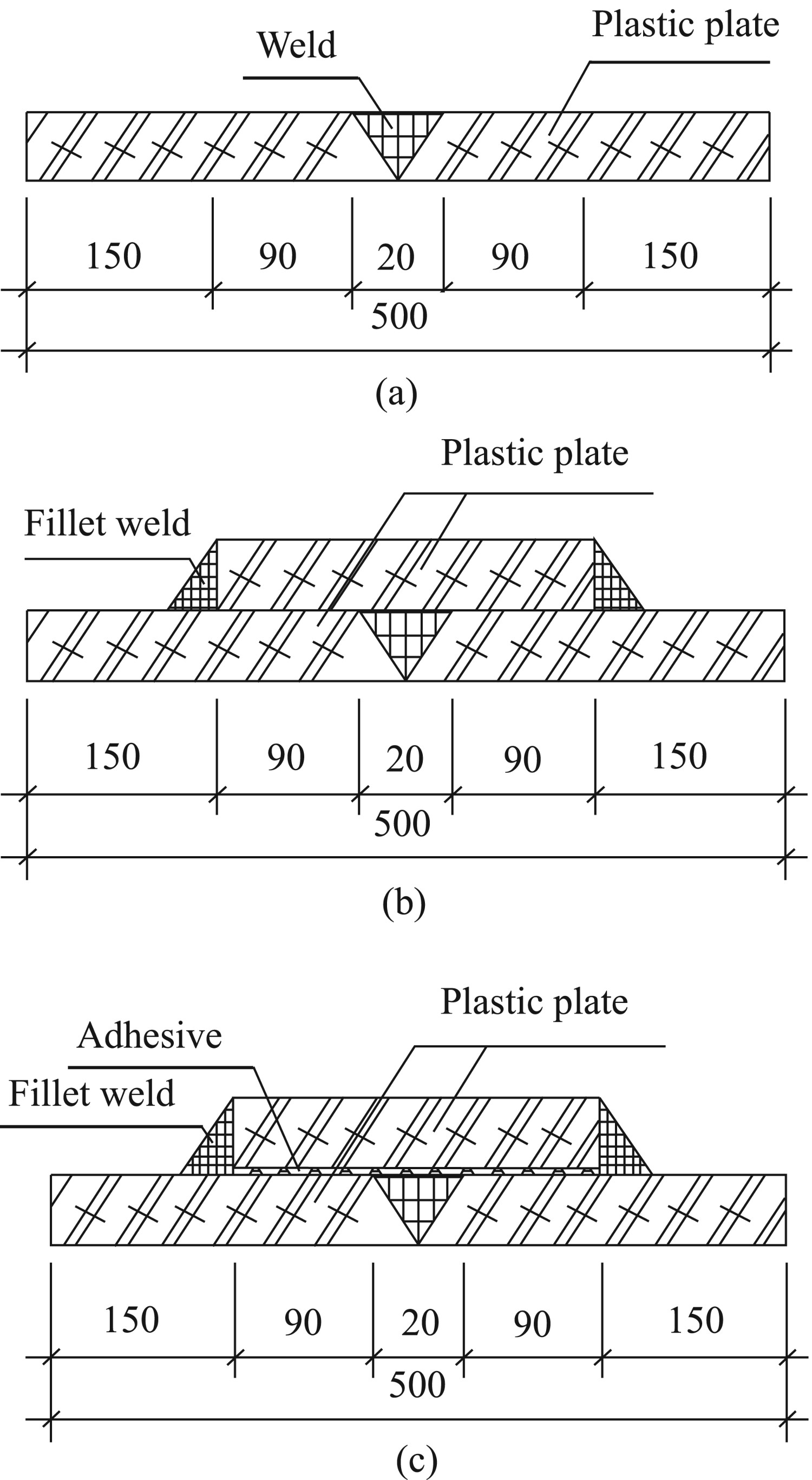
The parameters included the weld form and sheet thickness. The weld form was divided into groove-weld specimens, groove-weld specimens with welded cover plates, and groove-weld specimens with pasted and welded cover plates, with six specimens for each. Considering the economy, durability, and construction complexity of plastic welding technology, hot-air welding technology was adopted for the welding seam, and the binder was a two-component silicone structural adhesive. As indicated in Reference [18] (Figure 2), the splicing of the waterproof plate needs to be connected by a welding seam. Based on the stud distance and considering the practical operation at the construction site, the three weld forms and specific geometric dimensions designed are shown in Figure 3(a–c), where the width of the plate is 250 mm. The cover plate thickness was the same as that of the polypropylene plastic plate and was divided into 5, 8, and 10 mm.
Schematic diagram of polypropylene waterproof plastic plates. (a) Cross section of groove-weld specimens. (b) Cross section of groove-weld specimens with welded cover plates. (c) Cross section of groove-weld specimens with pasted and welded cover plates. Geometric form and dimensions of three welds.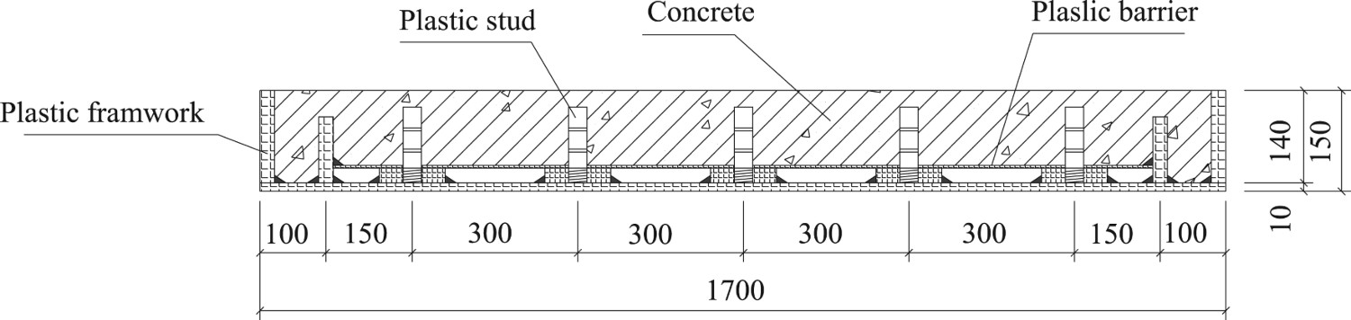
The plastic plate and welding rod were made of polypropylene plastic (Jinfeng Plastic Factory; Zhengzhou, China), the diameter of the welding rod was 4 mm, and a 142.640 hot-air welding torch (Ledan Plastic Welding Technology Co., Ltd., Shanghai) was selected. The maximum air outlet temperature was 650°C, and the maximum air outlet volume was 900 L min−1. For the groove weld, the polypropylene plastic plate was welded at a 45° angle along the welding edge, and two plastic plates were butted to form a 90° V-shaped groove. In addition, the gap of groove root is set to 0.5 mm for the best results [19]. Before welding, the two plastic plates were pre-welded with a welding rod to avoid slippage. Hot-air welding was carried out in accordance with HG/T 4281–2011 [20] at a welding pressure of 15–20 N, the temperature of the hot-air torch was 305°, and the air output was 40 L min−1. For the filet weld of the cover plate, the plastic plate at the welding angle was polished and levelled. The welding rod was then welded at a 90° welding angle with the welding gun, the welding parameters of which were the same as those of the groove weld.
Material property
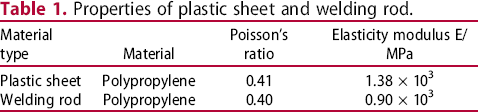
According to GB/T 1040.1-2018 [21] and ANSI/ASTM E132-1997 [22], tensile specimens (Figure 4) were applied, and a tensile test was carried out on a universal testing machine. The measured material properties of the plastic sheet and welding rod are listed in Table 1.
Tensile test specimens of polypropylene plastic. Properties of plastic sheet and welding rod.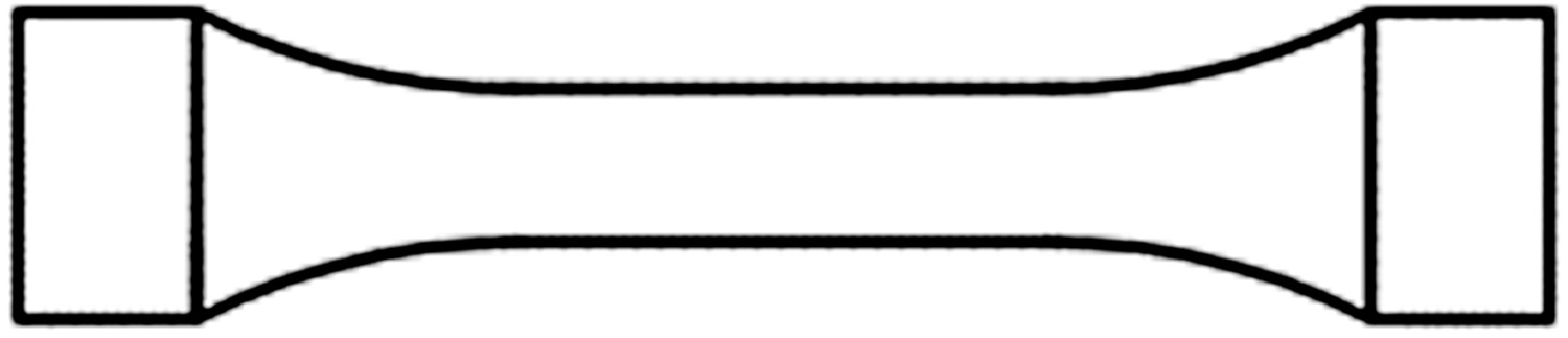
Test loading and measuring point arrangement
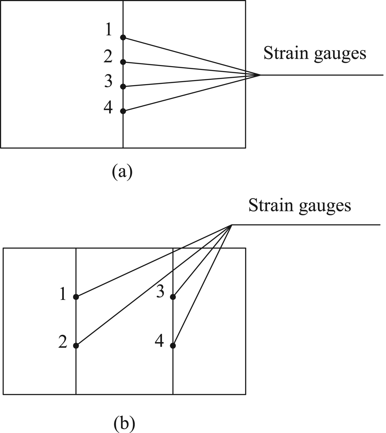
A QJ-1.5/14 automatic booster pump (Figure 3) was used to pressurise the specimen. The booster pump head was 0–100 m and a graded loading method was adopted. The loading rate was 0.05 MPa min−1. The water pressure was measured in real time using the water pump gauge. Figure 5 shows the field loading diagram of the polypropylene plastic weld. To further explore the stress of plastic welds under a water-pressure load and monitor the weld surface strain, an axial strain gauge was pasted on the welds of the specimens, as shown in Figure 6.
Field loading diagram. (a) Strain gauge positions for groove welds. (b) Strain gauge positions for groove welds with welded cover plates. Schematic diagram of the positions for strain gauges.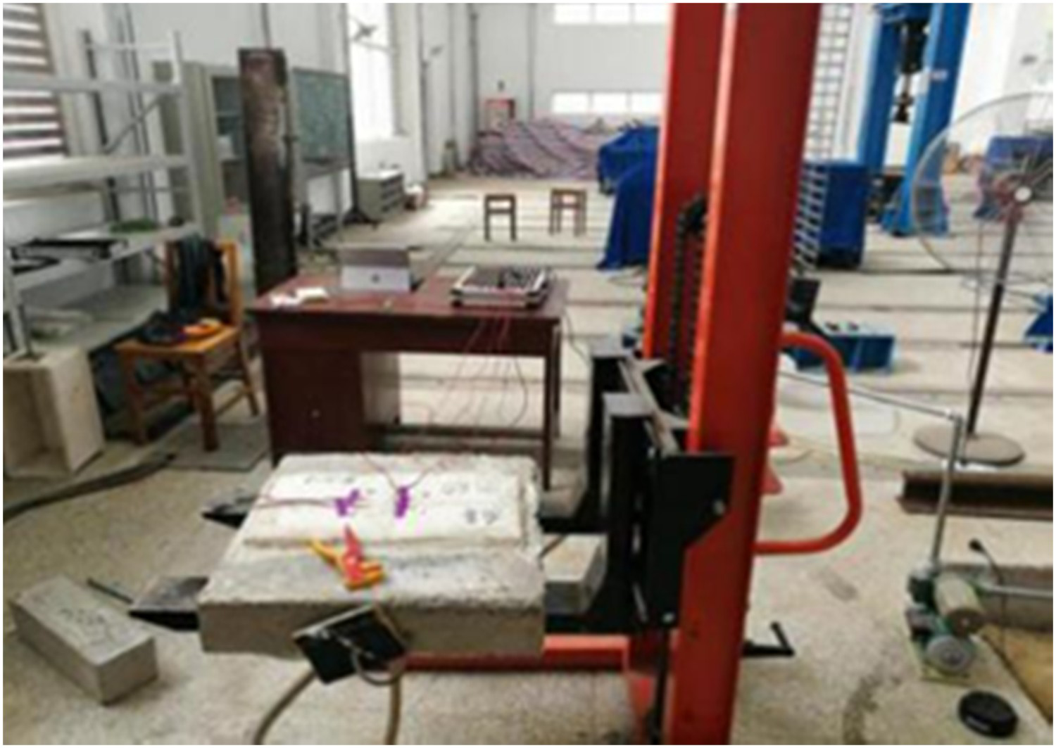
Test results and analysis
Failure test pattern
Statistical table of failure forms and pressure of specimens.
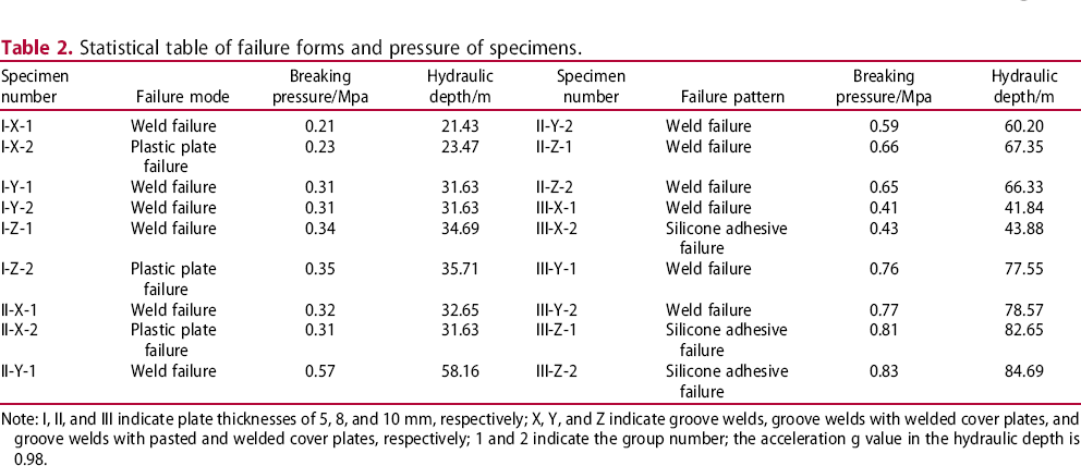
Note: I, II, and III indicate plate thicknesses of 5, 8, and 10 mm, respectively; X, Y, and Z indicate groove welds, groove welds with welded cover plates, and groove welds with pasted and welded cover plates, respectively; 1 and 2 indicate the group number; the acceleration g value in the hydraulic depth is 0.98.
Specimens undergoing a plastic plate failure were I-X-2, I-Z-2, and II-X-2 and account for 17%. The destruction of the PP plastic plate occurred near the joint of the weld seam and plastic sheet, which may have been caused by damage to the edge of the plastic sheet caused by the high temperature of the welding gun during welding, and the thickness of the plastic sheet decreased. Compared with the water pressure applied by the weld failure specimens of the control group, the water pressure corresponding to the weld failure is also reached when the plastic plate breaks, and the difference between the two is insignificant.
Specimens undergoing silicone structural adhesive failure were III-X-2, III-Z-1, and III-Z-2. In the experiment, the silicone structural adhesive between the specimens and the concrete board was washed away under the action of water pressure. The bonding strength of the fully solidified silicone structure adhesive is approximately 0.85 MPa [23]. When the bottom water pressure reaches or exceeds 0.85 MPa, the silicone structure adhesive between the specimen and the concrete board is unable to resist the water pressure and will be washed away. In specimens III-Z-1 and III-Z-2, owing to the increase in the plastic plate thickness and the existence of the cover plate and binder, the weld strength exceeds the damage of the silicone structural adhesive; thus, the water pressure strength is controlled by the adhesive bond strength.
Stress process analysis
Stress process of weld failure
Using a typical specimen, II-X-1, which was destroyed at the weld seam as an example, the pressure–strain relationship curves were drawn, as shown in Figure 7. The vertical coordinates represent the measured strain values at different measuring points. During the entire loading process, the strain values at measuring points 1 and 3, and at 2 and 4, were in good agreement with each other and showed an increasing trend. The strain values of measuring points 2 and 4 increased linearly. When the water pressure at measuring points 1 and 3 was increased from 0.1 to 0.15 MPa, the strain growth rate increased. The growth rate then slowed down again, which was basically the same as that at the initial loading stage. When the water pressure was loaded at 0.3 MPa, the welding seam was damaged, and the loading pressure was stopped.
Pressure–strain relation curves of specimen II-X-1.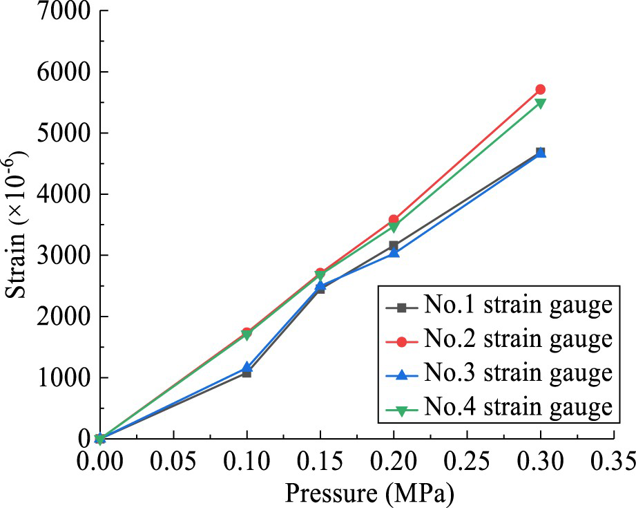
Figure 8 shows the pressure–strain relationship curves of typical specimens I-Z-1, II-X-1, and III-Y-1 destroyed at the weld seam. The vertical coordinate is the mean of the four measured strain values at the weld seam. As shown in the figure, the strain of the three specimens increased linearly with no obvious yield point, indicating that a weld failure is a type of brittle failure.
Pressure–strain relation curves of the weld failure specimen.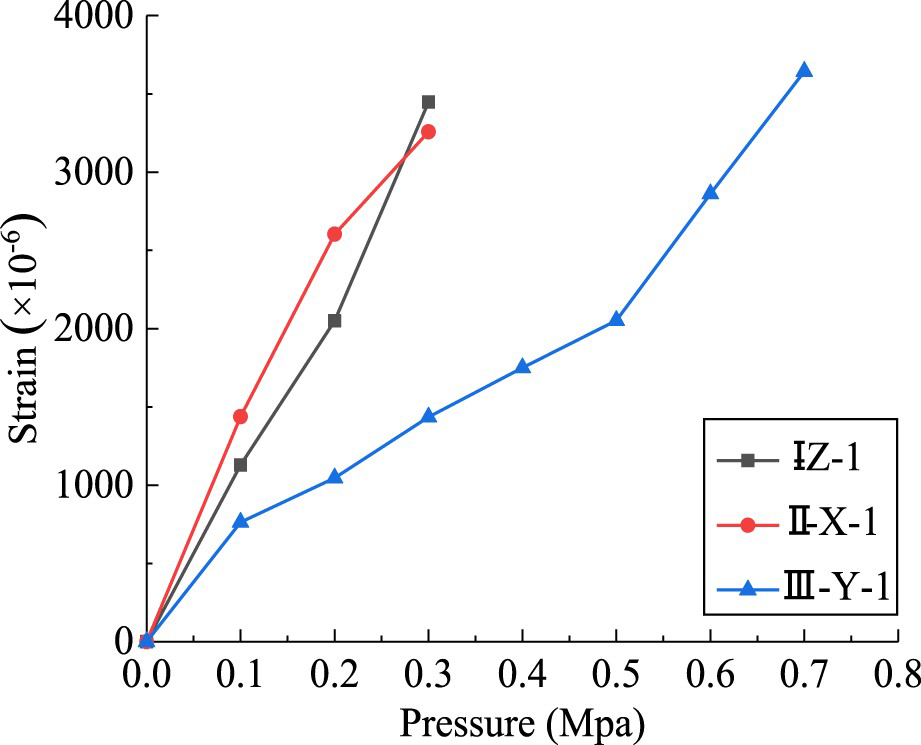
Stress process of plastic plate failure
Figure 9 shows the pressure–strain relationship curves of typical specimens II-X-2 destroyed at the plastic plate. The vertical coordinate is the measured value of the four measured strain values. It can be observed that during the process of water-pressure loading, the strain values at the weld increased. At the beginning of the loading, the strain growth rate was relatively slow. When the water pressure increased from 0.15 to 0.2 MPa, the strain growth rate increased significantly. After the water pressure reached 0.2 MPa, the strain growth rate slowed again, which was basically the same as the initial loading rate. The loading pressure was stopped until the plastic plate broke. At this time, the weld remained intact without damage.
Pressure–strain relation curves of specimen II-X-2.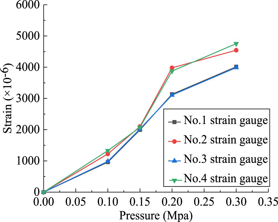
Figure 10 shows the pressure–strain relationship curves of specimens I-X-2, I-Z-2, and II-X-2 destroyed at the plastic plate. The vertical coordinate represents the mean of the four measured strain values. As shown in Figure 10, the plastic plate fracture specimens also exhibit a brittle failure, and the pressure and strain values at failure are similar to the pressure and strain values at the weld seam.
Pressure–strain curves of plastic plate fracture specimens.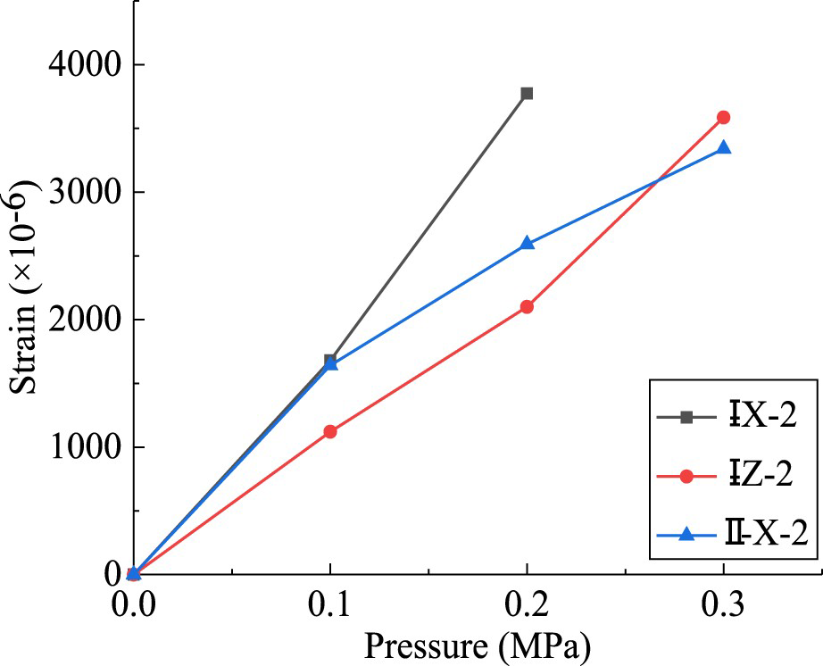
Adhesive failure
Figure 11 shows the pressure–strain curves of the silicone structural adhesive failure specimens III-X-1, III-Z-1, and III-Z-2. The vertical coordinate represents the mean of the four measured strain values.
Pressure–strain curves of adhesive failure specimens.
The strain increased linearly with pressure. Adhesive failure requires greater water pressure, and the strain value generated at the weld is relatively small, indicating a brittle failure.
Failure mechanism
The form of the X-weld is single, and the resistance to water pressure depends on the bonding strength of the welding rod and plastic plate; thus, the resistance to water pressure is weak. The form of the Y-weld is a cover plate using filet welding on the groove, which increases the stiffness of the groove weld; in addition, the resistance to water pressure for the Y-weld is significantly improved compared with that of the X-weld.
On the basis of the Y-weld, the cover plate and groove weld were bonded together using a two-component silicone structural adhesive, which further improved the rigidity of the weld and the anti-water-pressure capability.
For the weld failure specimens, the X-weld stress at the groove was at its maximum, and the weld was at the structural weak point. With the increase in water pressure, the stress at the welding seam also increased. When the failure stress of the weld was reached, the weld failed. For the Y- and Z-welds, when the stress at the filet weld reached the failure stress, the groove weld bore less stress owing to the constraint of the cover plate, and the filet weld was damaged before the groove weld. All failures of polypropylene plastic plate specimens occurred around the weld seam, which was probably because the high temperature of the welding gun caused damage to the plastic plate, reducing the mechanical properties of the plastic plate around the welding seam and the thickness of the plastic plate. Shear failure occurred when the stress concentration was high. Failure of the silicone structural adhesive occurred because the strength of the weld is greater than its bond strength. Under sufficient water pressure, the weld was not damaged, but the structural adhesive was.
Analysis of influencing factors
Weld form
Figure 12 shows the effects of different weld forms on resistance to water pressure. The capacities of the X-, Y-, and Z-welds to resist the water pressure increase successively when the plate thickness is the same. Compared with the X-weld, the water-pressure resistance of the Y-weld seam improved significantly, whereas that of the Z-weld seam improved less than that of the Y-weld seam. In the hydraulic test of the 5-mm-thick plate specimens, the anti-water pressure of the Y-weld increased by 40.9% compared with that of the X-weld, and that of the Z-weld increased by 9.7% compared with that of the Y-weld. In the hydraulic test of the 8-mm-thick plate specimens, the anti-water pressure of the Y-weld increased by 87.1% compared with that of the X-weld, and that of Z-weld increased by 12.1% compared with that of the Y-weld. In the hydraulic test of 10-mm-thick plate specimens, the resistance to water pressure of the Y-weld was increased by approximately 81% compared with the X-weld, and that of the Z-weld increased by approximately 7.9% compared with that of the Y-weld. Figure 13 shows the linear fitting of the plate thickness and water-pressure resistance in different weld forms. The fitting slopes of the 5, 8, and 10 mm plates are 0.039, 0.09, and 0.097, respectively. The slope ratio of the Y-weld to the X-weld is 2.31, and that of the Z-weld to the Y-weld is 1.08. With the increase in the plate thickness, the anti-water-pressure lifting capacity of the Y-weld is about twice that of the X-weld, and there is little difference between the Z- and Y-welds. In general, the design of the underground silo is no more than 35 m. Considering the cost, construction, safety, and other factors, it is recommended to adopt a Y-weld seam for a waterproof plastic plate.
Influence of weld forms on water-pressure resistance. (a) Form-pressure histogram of the 5-mm plastic plate (b) Form-pressure histogram of the 8-mm plastic plate. (c) Form-pressure histogram of the 10-mm plastic plate. Fitting curves of thickness strength.
Thickness
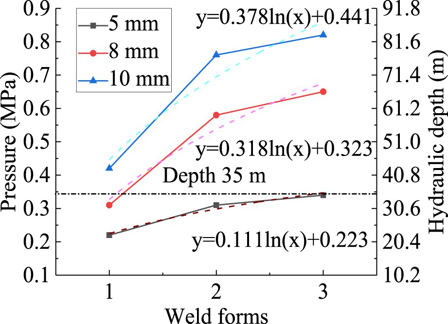
Figure 14(a–c) shows the resistances of the X-, Y-, and Z-welds to water pressure under different plate thicknesses. It can be observed that, with an increase in the thickness of the plastic plate, the strength of the welds increases, and the resistance to water pressure increases successively. The thickness of the polypropylene plastic plate increased from 5 to 8 mm, and the increases in the anti-water pressures of the X-, Y-, and Z-welds were 40.9%, 87.1%, and 91.2%, respectively. The thickness increased from 8 to 10 mm, and the water pressure of the X-, Y-, and Z-welds increased by 35.5%, 31%, and 26.2%, respectively. Figure 15 shows the linear fitting between the weld forms and the water-pressure resistance for different plate thicknesses, where abscissas 1, 2, and 3 are represented as X-, Y-, and Z-welds, respectively. The fitting curve is expressed as a logarithm and the fitting coefficient increases with an increase in the plate thickness. The coefficient ratio between 8 and 5 mm is 2.86, with an average increase of 0.95 per mm; in addition, the coefficient ratio between 10 and 8 mm is 1.19, with an average increase of 0.60 per mm. The lifting coefficient decreased with an increase in plate thickness. Considering the depth of an underground silo, it is recommended to use 8 mm for an underground waterproof plastic plate.
Influence of thickness of the water-pressure resistant plastic plate. (a) Plate thickness-pressure histogram of X-weld (b) Plate thickness-pressure histogram of Y-weld. (c) Plate thickness-pressure histogram of Z-weld. Fitting curves of the weld form versus strength.
Conclusion
The failure modes of polypropylene plastic weld specimens include weld, polypropylene plastic plate, and silicone structural adhesive failures. In the same weld form, the hydraulic pressure was the largest when the silicone structural adhesive was damaged, and the difference between the water pressure when the weld was damaged and the polypropylene plastic plate was insignificant. The resistance to water pressure of the welded cover plate on the groove weld is increased by approximately 40%–85% compared with that of a groove weld. The increase in anti-water pressure of the pasted and welded cover plate on the groove weld is weaker than that of the welded cover plate on groove welding, which is increased by approximately 10%. The anti-water pressure of the weld increased with an increase in the plastic plate thickness. Compared with the weld seam of the 5-mm-thick plastic plate, the weld seam of the 10-mm plate nearly doubles the water-pressure resistance. For the Y- and Z-welds, the increase in the anti-water pressure is significant when the plastic plate thickness ranges 5–8 mm. Considering the buried depth, cost, construction, and safety factors of an underground silo, 8-mm welded cover plates are recommended for waterproofing of an underground silo.
Footnotes
Disclosure statement
No potential conflict of interest was reported by the author(s).