
Abstract
The flow-induced fibre orientation formed during polymer extrusions causes the composite to exhibit non-homogeneous thermal-mechanical behaviours during Large Area extrusion-deposition Additive Manufacturing (LAAM) processes. This study numerically evaluates the fibre orientation state of a 20 wt.% short carbon fibre reinforced polyethylenimine fabricated by LAAM. The fibre orientation state of the solidified deposited bead is determined by a fully coupled flow/orientation simulation approach. The material properties of deposited composites are computed by assuming that the deposited bead has heterogeneous regions with varying local fibre orientation states. A finite element simulation is performed to model the LAAM process of a thin-wall structure, where the predicted inhomogeneous material properties are employed. Computed results show notable differences between simulations performed by employing homogenous properties and those obtained using heterogeneous properties. The bead-direction tensile stress contours computed under the heterogeneous assumption are comparable to experimental data in the literature, supporting our numerical approach.
Keywords
Introduction
Large Area extrusion-deposition Additive Manufacturing (LAAM) is a 3D printing technique that has seen rapid growth in the manufacturing of polymer composites due to its high efficiency and cost-effectiveness, which is enabled by the screw-extruder-based material feeding system [1]. Large-dimension composite parts and tooling are 3D printed directly through the LAAM technology with less cost in time and materials than conventional subtractive machining tools. Applications of LAAM-produced structures occur in the automotive [2], shipbuilding [3], and green energy [4] industries. Carbon fibre-filled composites provide higher stiffness and strength and lower thermal expansion compared to unfilled polymers, which enhance the mechanical performance of the fabricated structures. Nevertheless, reinforced virgin polymers with short rigid fibres result in an inhomogeneous material exhibiting anisotropic material behaviour. Prior research tested the material properties of printed parts made with Fused Filament Fabrication (FFF) where the elastic moduli [5], the thermal conductivity [6], and the thermal expansion coefficient of deposited composites [1] were shown to exhibit an anisotropic behaviour. Numerical studies have also been performed to expose the inhomogeneous material behaviour of carbon fibre composite FFF parts. Brenken et al. [7] used finite element simulation to show the effect of 50 wt.% CF/PPS anisotropic thermal conductivity on the thermal history during FFF processing. Compton et al. [8] simulated the time-dependent temperature response of a large area additively manufactured carbon fibre filled ABS part through the finite element method, where an anisotropic thermal conductivity was assumed. Their solution implied that higher thermal conductivity was detrimental to the success of the fabrication. Hoskins et al. [9] modelled the coefficient of thermal expansion of the deposited beads using a non-homogenised approach, where locally measured fibre orientation states were applied. The predicted residual thermal stress in a printed cuboidal part of CF/ABS compared well with the experimental scanning results [10].
The anisotropic material behaviour of a carbon fibre polymer composite LAAM-printed bead is often attributed to the complex fibre/matrix microstructure. Discontinuous fibres re-orient as the material is extruded and deposited onto the underlying substrate where the resulting fibre orientation within a bead exhibits significant local differences, as seen in Figure 1. While fibre orientation measurements for LAAM are limited in the literature, simulations have provided insights into mechanisms that contribute to flow-induced fibre orientation and the associated anisotropic material behaviour of LAAM-printed composites. Nixon et al. [11] are among the first researchers interested in the fibre orientation state within the FFF extrusion nozzle. They explored the effects of three different nozzle geometries on the resulting fibre orientation at the nozzle exit using the Moldflow (Moldflow Corporation, Framingham, MA, USA) simulations. Heller et al. [12] studied the impact of extrudate swell on the resulting fibre orientation in the FFF nozzle flow [12]. Wang and Smith employed a 2D axisymmetric nozzle flow model to understand the effect of non-Newtonian fluid rheology [13] and the screw-swirling motion [14] on the resulting fibre orientation of composites made by LAAM. In addition, Heller et al. [15] and Russell et al. [16] predicted the fibre orientation in the deposited bead using a 2D planar deposition flow model. The predicted orientation-homogenised material properties including effective elastic constants and thermal expansion coefficients exhibited a high degree of material anisotropy. These numerical studies are done following a weakly coupled formulation between the flow kinematics and fibre orientation evolution, such that the fibre presence in the flow is ignored during the computation of the flow. In contrast, Beversta et al. [17] employed the smoothed particle hydrodynamics method to simulate the development of transient flow during a planar deposition process [17], where the flow kinematics and fibre orientation were solved in a mutually coupled formulation. Wang and Smith developed a fully coupled flow-fibre orientation coupling finite element approach to evaluate the velocity and fibre orientation fields in a nozzle-extrudate flow [18] and a planar extrusion-deposition flow [19], where the quasi-steady state of fibre orientation computed in the extruded composites was used to compute the material properties of the bead. Accordingly, the mutually dependent impacts between the flow and fibre orientation are crucial in properly identifying the material flow and associated fibre orientation in LAAM and similar processes [20].
Complex local orientation across a composite bead extruded by LAAM.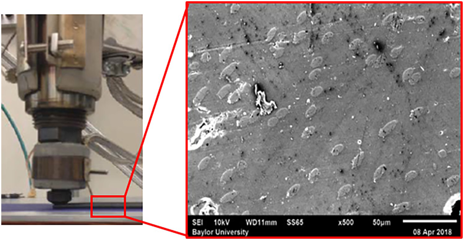
To further quantify the effect of local fibre orientation on the inhomogeneous material behaviour of LAAM-printed composites, a computational modelling approach is developed in this paper as follows. The fibre orientation state of a deposited composite bead is first identified by solving the flow kinematics and fibre orientation states in a 2D planar extrusion-deposition flow of the LAAM printing process. A fully-coupled flow/orientation simulation based on a finite element [18] is employed to solve the second-order orientation tensor over the entire flow domain. Additionally, the material properties of a printed bead are estimated using the fibre orientation homogenisation approach [21], including the elastic constants, coefficients of thermal expansion, and the thermal conductivity. Finally, by employing the estimated material properties, the time-dependent thermal-mechanical responses of a simple LAAM process are simulated via ABAQUS software (Abaqus Inc., Palo Alto, CA, USA). This is the first attempt to apply the macro fibre orientation predictions of LAAM-produced composites into a macro LAAM printing process simulation, to our best knowledge. The developed workflow is expected to provide a clear view to understand the impact of local fibre orientation on the material inhomogeneity of LAAM-produced composites.
Methodology
This section presents a numerical approach that explores the effects of the fibre orientation on the inhomogeneity of material properties of fibre-reinforced polymer composites fabricated via LAAM systems. The discussion includes governing equations for the fully coupled flow/orientation analysis in a 2D planar deposition flow model, the orientation-homogenisation approach for estimating the properties of composites, and the time-dependent thermal-mechanical coupled simulation.
2D planar deposition flow: identification of fibre orientation
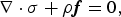
In concentrated fibre suspensions, the mutually dependent interaction between the flow and fibre orientation is considered significant [22]. This study employs a fully coupled analysis approach to quantify these fully coupled effects through a finite element-based approach, where MATLAB 2020a (The MathWorks, Inc., Natick, MA, USA) is utilised as the numerical solver (as did in [18]). An isothermal, incompressible, and highly viscous creeping flow is assumed, where the thermal gradients, the inertia effect, and the transient effect of time are neglected. Consequently, the mass and momentum conservation equations of the flow field are written, respectively, as [23]

 is the velocity vector,
 is the density of the continuum, and
 refers to the vector of body force. In the above,
 is the Cauchy stress tensor, which can be written as [23]

 is the identity matrix, and
 is the stress tensor associated with shear deformations. The latter can be written to include an anisotropic contribution from fibre orientation as [24]
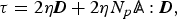
 is the viscosity of the melt. As shown in Equation (4), we assume an anisotropic Newtonian fluid model such that the melt viscosity is constant throughout the flow domain in the simulation. In the above,
 is the particle number that characterises the intrinsic anisotropic effect of the fibres on the flow rheology [25]. The tensor
 is the fourth-order fibre orientation tensor which will be introduced in the following section.
In this study. the Advani-Tucker orientation tensor equation with isotropic rotary diffusion is employed to model flow-induced fibre orientation as [21]


Here,
Coordinate the system defining the unit vector
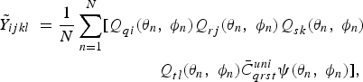
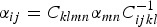
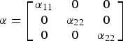
 is the unit vector depicting the orientation of a single rigid fibre along the axis of fibre alignment (cf. Figure 2). The angle bracket ‘< >’ refers to average overall orientation directions, weighted by the probability distribution function of the orientation [24]. Fibre aspect ratio enters the computation through the parameter
 evaluated as [21]

 is the hydrodynamic aspect ratio of the ellipsoidal fibre. In Equation (5),
 is the empirically obtained fibre interaction coefficient that provides a means for incorporating the effect of fibre-fibre interaction. Bay proposed an expression for
 as [26]

 is the fibre volume fraction within the polymer composite melt. In addition,
 and
and
 are the vorticity tensor and rate-of-deformation tensor of the suspension flow, respectively, which are written as

 indicates the velocity gradient and the superscript
 refers to the matrix transpose operation, and
 is the scalar magnitude of
 .
.
 .
.
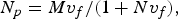
Additionally, the flow-fibre orientation coupling particle number
 is determined by the fibre volume fraction and fibre aspect ratio of the fibre suspension from [25]

A 2D planar deposition model as shown in Figure 3 is employed to model the extrusion-deposition flow, where the width of the extrudate normal to the plane of flow is assumed unity. The diameter of the nozzle exit is 1/8 inch, based on the geometrical design of a Strangpresse (Strangpresse Corp., Youngstown, OH, USA) large-scale additive manufacturing Model 19 single screw extruder nozzle, as given in [19]. The distance between the exit of the nozzle and material substrate (i.e., layer thickness) is 3 mm, which is typical in large-scale AM applications [15]. In addition, the bead length is set as 30 mm, which is ten times the layer thickness, so that a quasi-steady state of the fibre orientation can be assured. The boundary conditions of the flow domain are given in Table 1 (also see Figure 3).
2D planar deposition flow model. Boundary Conditions (BCs’) of 2D planar deposition flow.
In the above,
 is the tangential velocity, and
 is the normal velocity. In addition,
 is the tangential traction, and
 is the normal traction. The flow inlet velocity is fixed through the iterations. Although the overall coupled flow/orientation analysis is carried out by the customised MATLAB code, commercial software is employed to help pre-compute the necessary boundary conditions. A fully developed velocity profile is imposed at the flow inlet through ANSYS Polyflow (ANSYS Inc., Canonsburg, PA, USA), based on the volumetric flow rate of 304.8
 . This results in a relative deposition plate speed of 101.6 mm/s, simulating the high flow rate in large-area additive manufacturing processes (up to 19 kg/hr) [15]. Further,
 and
and
 respectively denote the velocity and the unit normal with respect to the free surface. Specifically, the extrusion-deposition flow changes direction as the extrudate contacts the print surface, which requires a separate free surface remeshing algorithm for the two free surface boundaries appearing in Figure 3. To accommodate the computation of the free surfaces, two subdomains are identified where the single free surface for each is calculated using the streamline-based method presented in [19]. The nonlinear solution of the fully coupled flow-fibre orientation simulation is computed iteratively by first calculating the velocity field with fixed fibre orientation field, and then solving the fibre orientation with fixed velocity field. The iteration continues until the change in the flow field solution between iterations meets the convergence criterion. Enforcing the convergence criteria on the velocity field is chosen since it has been found that this is more challenging to accomplish than the fibre orientation computation in our experience. The convergence of the velocity field is determined by the free surface identification, which is achieved as the error between the steady-state die swell ratio values in two successive trials is equal to or less than
 (i.e.,
 ) [18, 19]. Additionally, the initial mesh of the flow domain is generated using ANSYS Polyflow module without any predicted swelled-free surface applied. The flow domain composes of 2350 4-node quadrilateral elements with 2476 nodes, which has been shown as a computationally effective and efficient mesh quality in our case [19].
The hyperbolic form of Equation (5) requires an initial condition of the second-order fibre orientation tensor for the flow domain. Herein, we imposed a fully random fibre alignment for the entire flow domain except for the specialised boundary conditions, in a manner similar to that shown in [16, 27]. The fibre aspect ratio is set to
 15 in an averaged sense, which is a safe estimation based on related experiments (see, e.g., [28, 29]). The interaction coefficient
 is set at 0.0055, as computed by Equation (8).
Orientation-homogenised material properties
The fibre orientation in the 2D planar deposition flow exhibits significant spatial variation locally (cf. Figure 1), which we assume provides the primary source of spatially varying material anisotropy within LAAM-printed beads. The orientation homogenisation approach has experienced widespread application to estimate material properties of short fibre reinforced composites in polymer processing [30, 31]. Particularly, Müller and Böhlke suggested that the inhomogeneity of the predicted effective elastic constants is significantly dependent on the fibre orientation state [32]. To this end, we consider the orientation homogenisation approach in characterising the local inhomogeneous material properties of LAAM-printed composites.
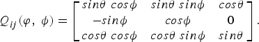
Advani and Tucker first proposed evaluating the material stiffness of discontinuous fibre filled composites by homogenising the fibre orientation within the material [21]. Following the Voigt procedure (i.e., the mean strain is assumed constant over a subdomain), Jack and Smith [33] expressed the sample mean material stiffness tensor
 of each subdomain from the corresponding fibre stress field as
 and
and
 are defined as in Figure 2. In Equation (8),
 is the rotation tensor
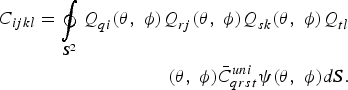
In the above, the fourth-order tensor
 is the material stiffness tensor of a reference unidirectional composite computed using the Tandon-Weng Equation [34],
 is used to rotate material stiffness tensor from its local coordinates defined by
 , and
, and
 is computed with respect to the global coordinate system. In this approach, the sample mean material stiffness tensor
 is an unbiased estimator of the population mean for a given distribution (see, e.g., [33]). For a given set of angles (e.g., {
 }), as
 , the sample mean stiffness tensor approaches the expected value, or the point-wise mean stiffness tensor of a subdomain,
 , given as

 and
and
 . The material constants
 , I = 1, … ,5 in Equation (16) are computed from
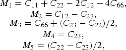
 are components of the stiffness tensor for the associated unidirectional fibre filled composite (i.e.,
 ) written in contracted notation. In the present study, we compute
 using the modified Tandon-Weng micromechanics model, which has proven to be an effective and sufficiently accurate formula for estimating the elastic properties of discontinuous fibre-reinforced composites [36]. Wang et al. showed that the variation in fibre length composites prepared through large-scale screw-based additive manufacturing systems also had a direct impact on the material properties [29]. For simplicity, herein we consider a weight-averaged fibre aspect ratio for the computation of material properties homogenisation.
A similar method can be used to evaluate the coefficient of thermal expansion (CTE) of a composite composed of short misaligned fibres, which is given by Camacho et al. [37] as
 is the stiffness tensor given in Equation (16). The
 term in Equation (18) is defined as

 and
and
 are given as


In Equations (20) and (21),
 and
and
 are defined as


 and
and
 are the longitudinal and transverse components of the transversely isotropic CTE tensor,
 , for a unidirectional composite in the
 and
and
 directions, respectively. Stair and Jack [38] produced a tensor form for a transversely isotropic unidirectional composite written as
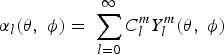
The orientation homogenisation model for thermal conductivity of misaligned short fibre filled polymers has been done previously [40]. The derivation follows a similar approach as that presented by Jack and Smith [33]. First, consider the Laplace series for the orientation distribution function given as
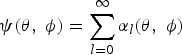
 is an invariant subspace of the orientation distribution function, dependent on the angles of the principal fibre vector
 given as
 and
and
 (cf. Figure 2). The invariant subspace
 is defined as
 is the
 -order complex spherical harmonic function. It is worth noting that all odd invariant subspaces are zero due to the fibre orientation distribution function being symmetric. The invariant subspaces
 and
and
 can be cast as
 is the Kronecker delta. The fourth, sixth, and all even ordered invariant spaces exist but can be truncated at the second ordered invariant subspace, as shown by Jack and Smith [33] due to the orthogonality of all increasing even ordered invariant subspaces. The fibre orientation distribution function truncated to the second order can be stated as

 as appears in Equation (14), we also introduce the thermal conductivity tensor for unidirectional fibre filled composites which is given as
Note that
 for unidirectional composites. The orientation averaged thermal conductivity tensor for misaligned fibres can be written using rotation matrices presented in Equation (14), the thermal conductivity tensor for unidirectional short fibre composites given in Equation (30), and the orientation distribution function given in Equation (29), which is given as
 is the area of the unit sphere. The thermal conductivity tensor can be written in terms of orientation tensor components and thermal conductivity components as
 ,
,
 , and
, and
 are defined as
 and
and
 direction, i.e.,
 and
and
 , respectively, are defined as
 is given as
 and
and
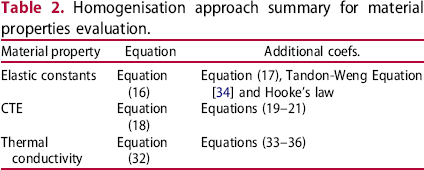
 directions are equal. A summary of the homogenisation approach on the mechanical properties is finally given in Table 2.
Homogenisation approach summary for material properties evaluation.
Time-dependent thermal-mechanical responses of a LAAM process
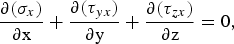
To simulate the additive process (i.e., material volume continues increasing), the built-in element activation/deactivation function in ABAQUS is employed. We employ the coupled thermal-displacement analysis in ABAQUS to compute the bead deposition temperature field, thermal deformation, and residual stress. The governing equation for energy conservation can be written as, 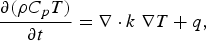
 is the temperature,
 is the material density,
 is the mass-specific heat,
 is the coefficient of thermal conductivity, and q is the heat generation rate. In addition, the governing equations for the mechanical stress analysis can be written as

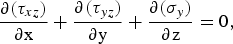
In addition, the thermal strain is computed as
 is the CTE and
 is the reference temperature.
The thermal boundary conditions for the bead deposition model domain include a fixed temperature (
 ) for nodes in contact with the print substrate and the ambient temperature (
 ), such that

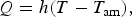
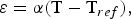
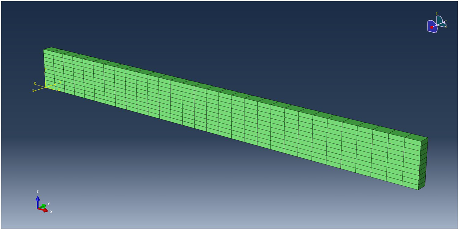
The transient printing process finite element simulation is performed with ABAQUS explicit using the built-in element activation/deactivation function, where deposited beads are divided into cells of unit volume, as shown in Figure 4. Along the z direction, the unit cell is sliced into multiple layers where each layer is assigned thermal and mechanical properties based on the fibre orientation output of the extrusion-deposition simulation described above. The thickness of each cell is 3 mm which is the same as that modelled in the 2D planar flow simulations above. The width of the cell is defined as 8 mm, which is commonly seen in LAAM applications, to our knowledge. The printing speed (i.e., nozzle moving speed) is the same as that imposed in the 2D planar flow modelling above (i.e., 101.6 mm/s, as imposed in Table 1). Based on these inputs, the activation time between unit cell activation along a simulated printed bead is 0.1 s. Consequently, the overall size of our simulated domain is 304.8
LAAM printing process simulation via ABAQUS. 30
30
 8mm3. Properties of 20% CF/PEI carbon fibre composite are employed in the material model in this study. Accordingly, the extrusion temperature (i.e., the initial condition for each activated element) is set as 380
 [42], and
 and
and
 are 90
 . In addition, the heat convection coefficient is estimated as 86 W/m2 K, according to forced-convection analysis with 20 m/s parallel airflow at 75
 [43].
[43].
Results and discussions
This section presents the computed results of fully coupled fibre orientation tensors in a 2D planar extrusion-deposition flow. The material properties of a deposited CF/PEI bead are evaluated based on second-order fibre orientation tensors at the end of the 2D planar flow via the orientation homogenisation approach. With the predicted material properties of a single deposited bead, the time-dependent thermo-mechanical simulation for printing a thin wall is then performed using ABAQUS. Finite element results including temperature fields, displacement fields, and stress contours of the printed domain, are given.
Local-orientation-affected material property inhomogeneity
Contours of computed melt flow velocity
 and
and
 are presented, where the normalised velocity contours
 and
and
 appear in Figures 5 and 6, respectively. The subscripts refer to the x 1, and x 2 directions shown in Figure 3. We see that significant variations occurred in the transition zone between the vertical extrusion and the subsequent deposition. It is then expected that the principle fibre orientation state may exhibit significant changes in this transition area. In addition, the die swell ratio at the flow end solved is 0.96 (i.e., the ratio of the thickness of the flow end to the theoretical bead thickness (i.e., Figure 3)), which is caused by the addition of the fibres [18]. As only little differences shown between the predicted extrudate swell and the theoretical bead thickness, we applied the 3 mm bead thickness in the macro-printing ABAQUS simulations presented in the next section. Moreover, computed values of the second-order orientation tensor component
 , and
, and
 are plotted in Figures 7 and 8, respectively. These diagonal components of the second-order orientation tensors represent the fibre alignment expectation with respect to each of the coordinate directions. Note that A11 is the fibre alignment expectation along the direction of the printed bead, which is the primary focus of the study (i.e., The principal fibre alignment direction). It is seen that the primary fibre orientation direction varies considerably during the extrusion-deposition transition. The deposited bead flow exhibits an uneven fibre orientation state where the lower half of the bead towards the print substrate exhibits a higher principal fibre alignment as compared to the upper half of the flow, which is similar to results shown in prior literature [11, 17, 19]. The fibre orientation pattern reaches a quasi-steady state rapidly after the 90°-turn that connects the extrusion and deposition. Herein, we assume that the steady-state fibre orientation is achieved at the end of the flow domain, which is considered to represent the fibre alignment of solidified deposited composite bead.
 contour of the fully coupled flow-fibre orientation solution at standard deposition rate. The values are normalised by the maximum magnitude of
 , 109.3 mm/s.
 contour of the fully coupled flow-fibre orientation solution at standard deposition rate. The values are normalised by the maximum magnitude of
 , 146.9 mm/s.
 contour of the fully coupled flow-fibre orientation solution at standard deposition rate.
 contour of the fully coupled flow-fibre orientation solution at standard deposition rate.
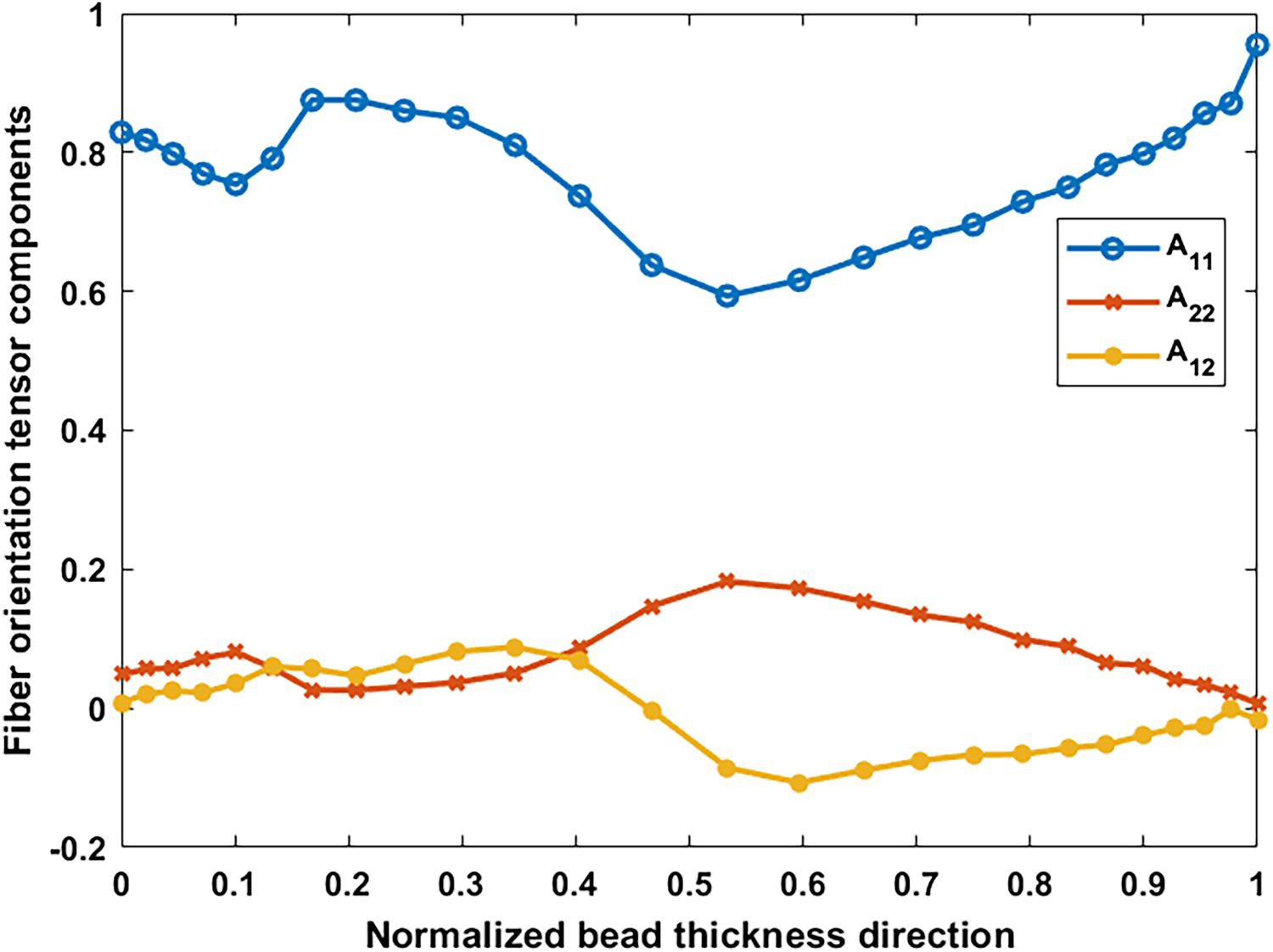
The components of the steady-state second-order fibre orientation tensors at the end of the flow domain are plotted in Figure 9. The x axis in Figure 9 refers to the normalised distances along the bead thickness, i.e., y/y0, where y0 denotes the bead thickness at the low outlet. The material properties of the deposited composite bead are then evaluated using the orientation homogenisation approach [35], combining the fibre orientation results shown in Figure 9. At each location where fibre orientation tensors are predicted, material properties, including elastic constants, thermal conductivity, and expansion coefficients, are computed using equations in Table 2. Prior studies computed effective thickness-averaged material properties of a deposited bead by numerically integrating the property of interest through the thickness of the bead [11, 17, 19], e.g., Fibre orientation tensor components at the flow end through the bead thickness. Deposited bead partition paradigm in 2D planar flow view. Error bars of A11 components at the end of flow for three sub-divisions. The maximum and minimum errors of the error bars for different number of subdomains.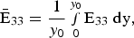
 exhibits notable local variation, where three local maximums and two local minimums appear along through the thickness of the bead. In this case, the maximum difference between the extremes is 0.3577, which is more than 50% of the extreme minimum (cf. Figure 9). To this end, it is expected that the fibre-orientation-dependent material properties within a LAAM-printed composite vary through the thickness in addition to having the anisotropic mechanical performances reported in the literature [9]. Hoskins et al. measured the coefficients of thermal expansion on LAAM-printed ABS composites which showed a similar trend as seen in
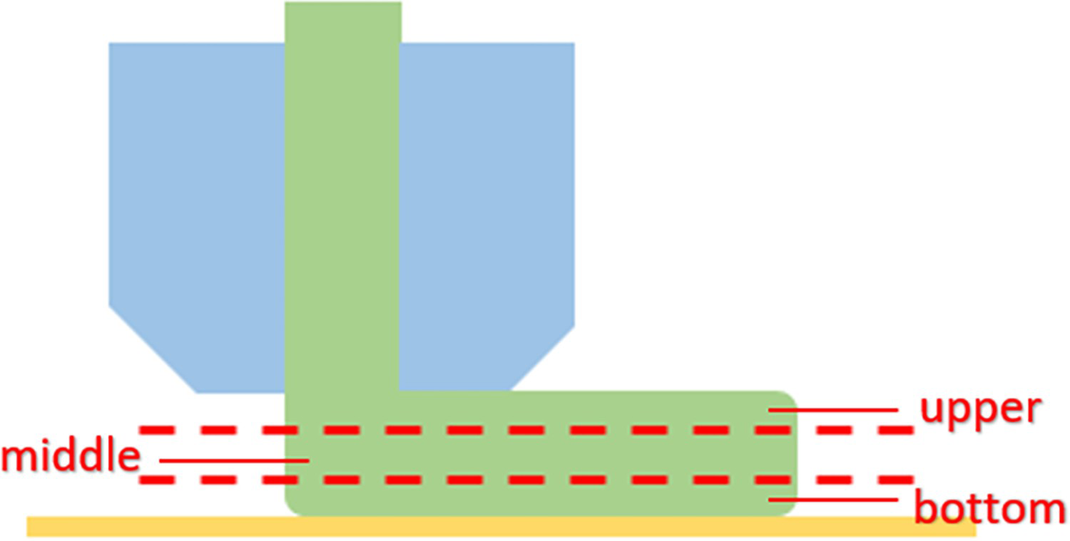
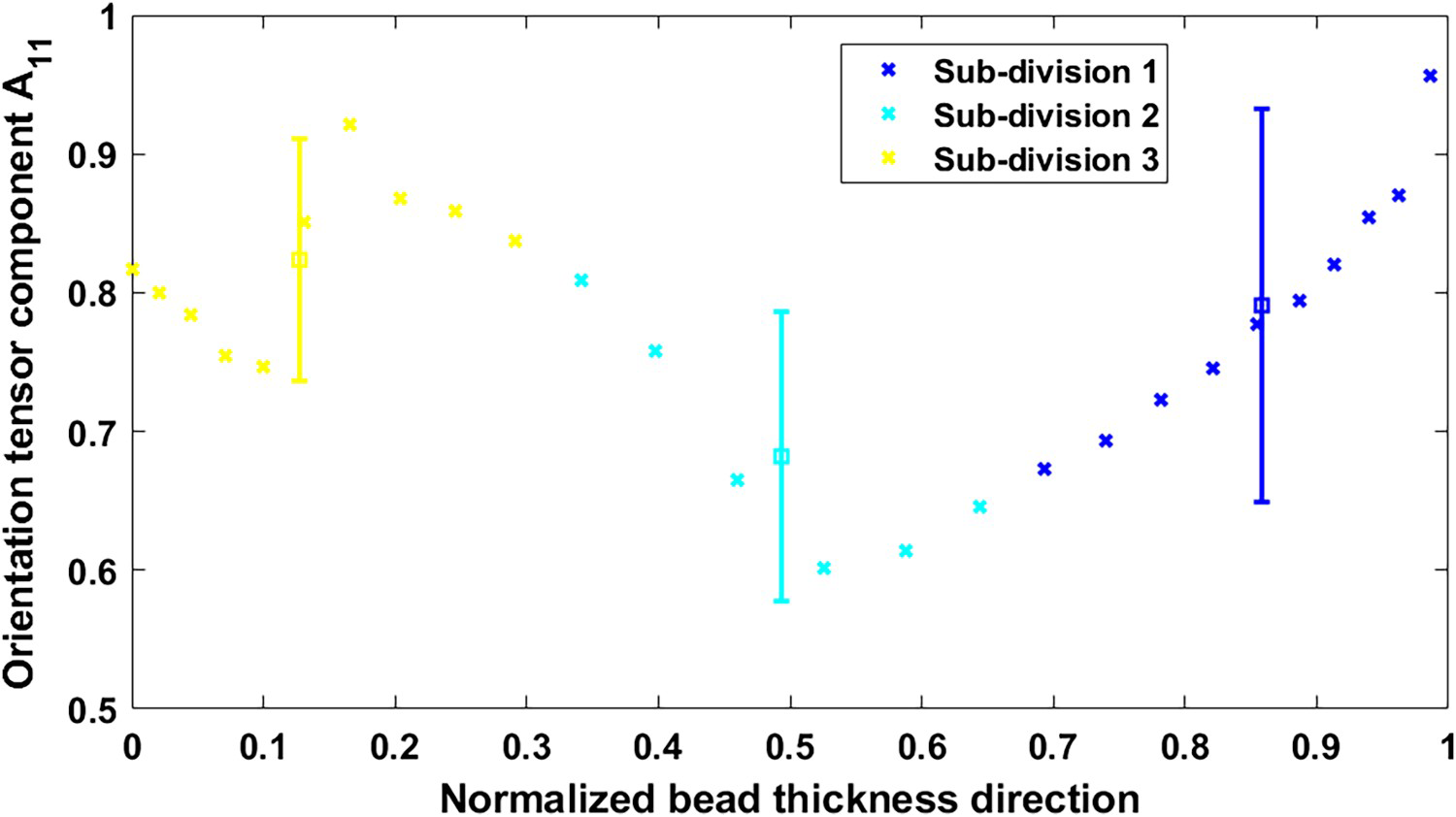
 components appearing in Figure 9 [9]. In simulating the residual stress of LAAM-printed parts, Hoskins et al. partitioned the deposited strand into five subdomains where each havs its own material properties that were estimated based on their measured data [9]. Herein, a similar strategy is employed to obtain deposited CF/PEI composites for further printing process simulation. The bead is divided into three equal subdomains through the bead thickness as shown in Figure 10. Then, material properties for each subdomain are estimated using the same orientation approach described above by performing a numerical integration similar to that in Equation (44) where unique limits of integration are defined for each subdomain. The error bars for fibre orientation tensor component
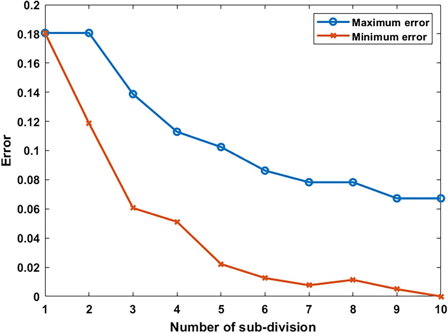
 in each sub-domain appear in Figure 11 which shows that the error bar of the upper subdomain is larger than that in the remaining subdomains. To further explore how the differences in orientation tensors values affect the printing process simulations of LAAMs, we compute ten sets of subdomains through the thickness of the bead from 1 to 10 subdomains. Error bars for the ten study cases are given in Figure 12. As expected, the extreme errors reduce as the number of subdomains increases, however, error results show little change beyond about seven subdomains. As a result, we would expect little effect in the printing process simulation results as the number of subdomains for material properties exceeds seven.
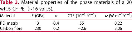
Material properties of the phase materials of a 20 wt.% CF-PEI (∼16 vol.%).

 (W m−1°C−1)
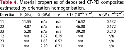
Material properties of deposited CF-PEI composites estimated by orientation homogenisation.

 (W m−1°C−1)
Effects of property inhomogeneity on thermo-mechanical responses of LAAM prints
A time-dependent thermo-mechanical coupled simulation is performed via ABAQUS for the LAAM printing process of a thin wall in 318 mm length × 8 mm width × 30 mm height. The simulation models a printing process that is 30 s in length with 30 cells in length × 1 cell in width × 10 cells in height, (cf. section ‘Time-dependent thermal-mechanical responses of a LAAM process’). To explore the influences of material inhomogeneity on the simulations, the one-subdomain and four-subdomain model for the material definitions are employed. To avoid the effect of finite element mesh, we applied the same mesh for the two simulation events. That is, each extrusion cell in the simulation is equally divided into four pieces. The simulation using one subdomain bead material property model defines the four pieces with the same material properties, while the simulation using four subdomain material properties defines each of the four pieces with a unique material property. As the material properties are obtained from a 2D planar flow simulation described above, we herein focus on simulating printing in a single plane. Note that the
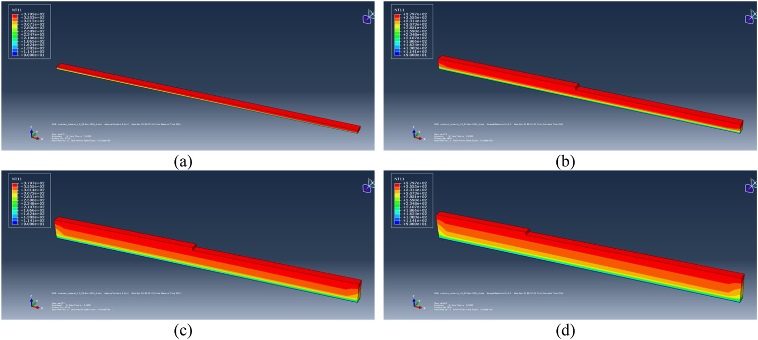
Temperature history of a printed part simulated by using a one-subdomain material definition: (a) t = 3.0s;(b) t = 4.5s; (c) t = 22.5s; (d) t = 28.0s. -
-
 plane defined in Figure 3 refers to the XZ plane defined in the ABAQUS simulation (cf. Figure 4). It is important to note that the printing direction of LAAMs affects the material anisotropy of the deposited beads as fibres tend to align along the direction of material loading. Nevertheless, we apply a unidirectional in-plane printing path, i.e., the positive direction of the x-axis. The material orientation for the properties defined in ABAQUS uses the same global coordinate system as shown in Figure 4. An example of the printing simulation process is given in Figure 13, where the temperature history computed by the one-subdomain material definition is presented.
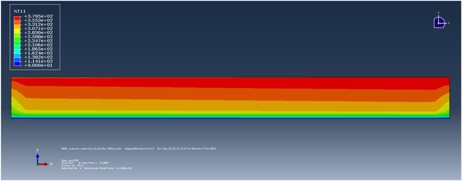
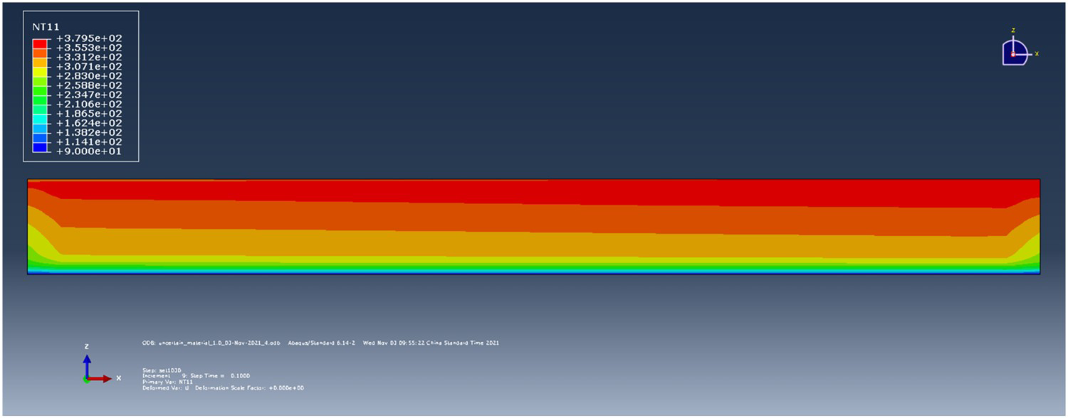
The temperature field from simulations employing uniform (i.e., having a single subdomain of material in the bead) and non-uniform (i.e., having four subdomains of material in the bead) homogenised properties are shown in Figures 14 and 15, respectively. Note that the temperature contours are shown for the as-printed beads (i.e., bead temperature for the entire model at the end of the print simulation). These results show that the inhomogeneity of material properties yields subtle influences on the computed temperature field at the end of printing. Similarly, we also see that the computed displacements of the as-printed beads similarly do not exhibit notable dependence on the choice of subdomains, either. Once the print simulation was complete, the thermal response for the entire model was computed as the printed part was cooled for 600 s with an ambient temperature of 90
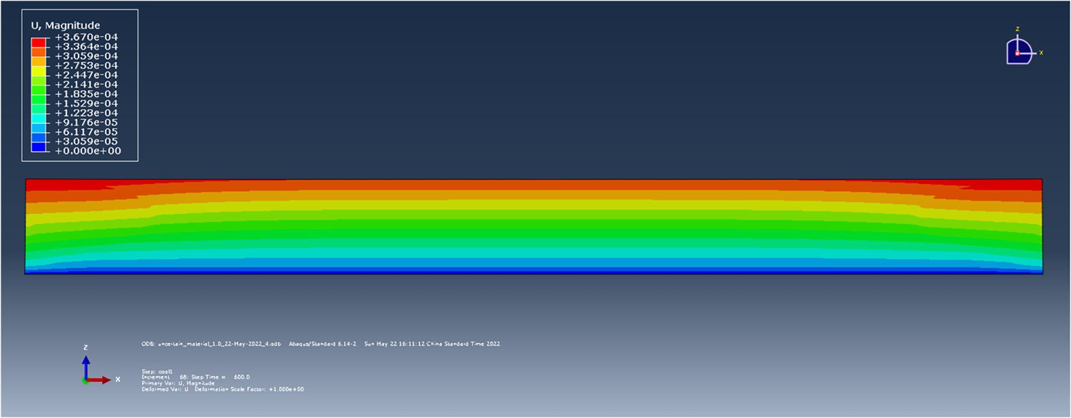
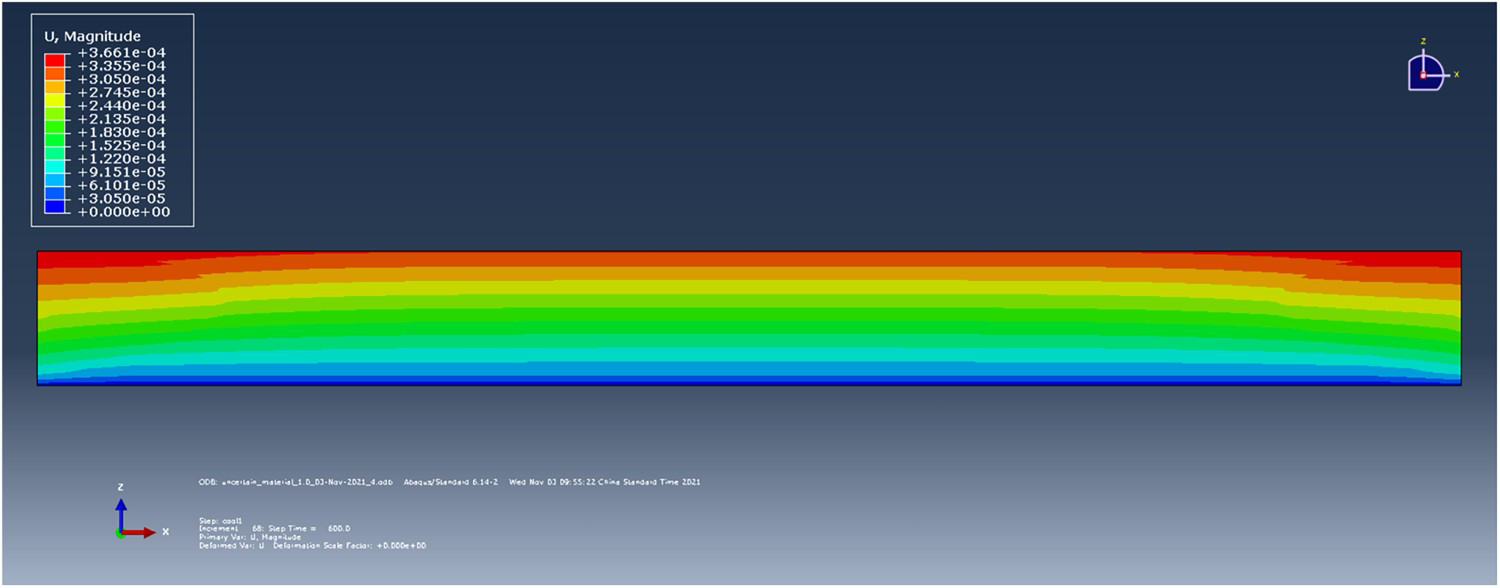
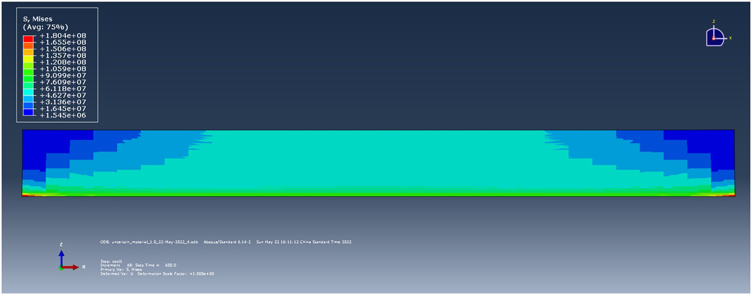
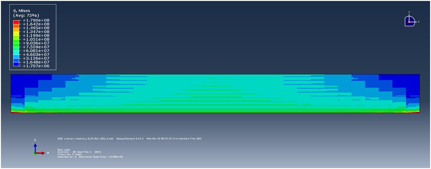
As-printed temperature field with one-subdomain material property model. As-printed temperature field using the four-subdomain material property model. Displacement magnitude using the one-subdomain material property model at 600 s after the print finishes. Displacement magnitude using the four-subdomain material property model at 600 s after the print finishes. Mises stress results using the one-subdomain material property model 600 s after the print finishes. Mises stress using the four-subdomain material property model 600 s after the print finishes.
 (resulting in a model temperature of 90
 2
2
 . The resulting displacement of the ‘cooled’ part using one subdomain and four subdomains of material properties are shown in Figures 16 and 17, respectively. The difference between the maximum displacement (0.367 and 0.366 mm for the one-subdomain and four - subdomain models, respectively) for these two cases is nearly the same, differing by only 0.27%). Nevertheless, the stress contours of the simulations in the cooled conditions (cf. Figures 18 and 19) provide a different perspective on the influence of material inhomogeneity in deposited composites. In these stress contours, the model with non-uniform properties yielded a less evenly-distributed thermal residual stress than that having uniform properties. Furthermore, the variation in the cooled state of the residual stress in the printing direction (i.e.,
 , also known as S11 in ABAQUS), as shown in Figures 20 and 21, provides more insights. Firstly, the modelling having uniform properties yields a quasi-uniform stress contour, while the results from the four-subdomain model exhibit notably non-even distribution in the sides of the printed part. This is attributed to the non-uniformity of the material properties due to a variation in fibre alignment in the deposited beads, as shown in Figure 7, where the upper half of the flow exhibits a dramatical different fibre orientation pattern as compared to the bottom half of the flow. In addition, the non-evenly distributed residual stress contour shown in Figure 21 is in line with an experimental measurement on LAAM-printed CF/ABS blocks [9]. This agreement is also considered to support our argument that the fibre orientation affected material inhomogeneity greatly impacts the simulation results of LAAM processes.
 stress contour using the one-subdomain material property model 600 s after the print finishes.
 stress using the four-subdomain material property model 600 s after the print finishes.
From the above results, it is seen clearly that the thermal stress results are most significantly affected by the material properties definition. To this end, we further performed simulations using an additional number of subdomains for the extrusion bead material definition, including one, two, four, and eight subdomains. Note, in all simulations, each extrusion cell (i.e., elements activated in one analysis step) is equally divided into eight pieces. The material definition for each piece is dependent on the selection of subdomains, as did previously. The
Selected representative x-axis locations, where the predicted
As-printed
Selected representative z-axis locations, where the predicted
As-printed
 stress results are studied in the following, as the property is dominant for the computed Mise stress results (cf. Figures 18–21). We first study the stress results as the printing process just finished (i.e., as-printed condition). The
 results at selected representative locations along x-axis (cf. Figure 22) are plotted over their corresponding z-axis coordinates, as shown in Figure 23. Among the selected x locations, it can be seen that the predicted differences are less notable at x = 312.7 mm compared to the others. In addition, the differences are seen mainly around the intermediate regions of the domain along z-axis (i.e., z = 5∼20 mm), Moreover, the
 results at selected representative locations along z-axis (cf. Figure 24) are plotted over their corresponding x-axis coordinates, as shown in Figure 25. In general, the magnitude of
 reduces as x coordinates increases, which indicates that the thermal residual stress accumulates mainly in the starting point of the printing process. Additionally, the differences between the predicted results converge as the unit extrusion cell is defined by more subdomains. Nevertheless, the two-subdomain material definition simulation exhibits similar predicted results as the finer eight-subdomain simulation. This is considered as a result led by the local fibre orientation predicted in Figure 9, from where it can be seen that the local variation of the fibre orientation can be basically seen in two intervals (i.e., equally divided into two subdomains).
 results are presented.
 stress results along z-axis direction: (a) at x = 79.5 mm; (b) at x = 164.3 mm; (c) at x = 249.1 mm; (d) at x = 312.7 mm.
 results are presented.
 stress results along x-axis direction: (a) at z = 5.8 mm; (b) at z = 11.8 mm; (c) at z = 17.8 mm; (d) at z = 26.8 mm.
Furthermore, we reproduce the above discussion with predicted data 600 s after the print finishes (i.e., at the cooled-down condition) in Figures 26 and 27, respectively. It is firstly seen that at selected x locations, the predicted
Cooled-down
Cooled-down
 oscillates significantly, as more subdomains are employed for unit extrusion cell material definition (cf. Figure 26). In addition, the differences in predicted results among the simulations are far more intense as compared to those shown in Figure 23, which indicates that the simulated cooling process is also affected by the locally material inhomogeneity. In contrast, the data trend shown in Figure 27 is similar to that appeared in Figure 25, except that the magnitude of the stress value increases notably. It should be noted that the relative differences between the one-subdomain and eight-subdomain simulations are within 5∼6 MPa for results shown in Figure 27, while those shown in Figure 26 are mainly in −10 ∼ + 6 MPa (especially in Figure 26b), which implies that the locally material inhomogeneity yields more influences on the stress accumulations along the direction of material addition, as compared to the direction of the in-plane material loading.
 stress results along z-axis direction: (a) at x = 79.5 mm; (b) at x = 164.3 mm; (c) at x = 249.1 mm; (d) at x = 312.7 mm.
 stress results along x-axis direction: (a) at z = 5.8 mm; (b) at z = 11.8 mm; (c) at z = 17.8 mm; (d) at z = 26.8 mm.
Finally, we explore the co-relations among the cooling-time effects, the locally-different material properties and the simulated thermal-mechanical results, by presenting the predicted
Predicted
Predicted
Predicted
Predicted
 stresses along z-axis direction at x = 249.1 mm are studied, as an example. The cooling process is simulated using adaptive step increment options, and there are 68 increments used for the 600-second cooling process simulation. We export the data from these steps and then impose linear interpolations between successive time increments to further generate a three-dimensional surface plot, aiming to present the variation of predicted
 stress results over the entire cooling process. The surface plots appearing in Figures 28–31 are simulated results using one-subdomain, two-subdomain, four-subdomain, and eight-subdomain material definitions, respectively. It is firstly seen that the most severe stress accumulation is near z = 0 mm. This is resulted by the pre-defined boundary condition on the bottom surface, such that a perfect bonding condition between the extruded beads and the material substrate is assumed, and thus no mechanical displacement occurs during the entire simulation. As the cooling process goes, the magnitude of thermal stress among the entire domain increases generally. With more subdomains employed in the material definition of the extrusion cell, it is seen that the stress contour becomes more non-evenly distributed. This non-uniformly distribution is directly related to the local inhomogeneity of the defined material properties, which may significantly reduce the stability of mechanical performances of LAAM-produced parts, as discussed in [9] (where a similar non-uniform stress contour is experimentally measured for a LAAM-produced CF/ABS wall structure). To this end, we stress the importance of understanding locally-variant-fibre-orientation-induced material properties inhomogeneity of fibre-filled composites produced by LAAM and similar processes.
 stresses along z-axis direction verses cooling-time, at x = 249.1 mm using one-subdomain material definition.
 stresses along z-axis direction verses cooling-time, at x = 249.1 mm using two-subdomain material definition.
 stresses along z-axis direction verses cooling-time, at x = 249.1 mm using four-subdomain material definition.
 stresses along z-axis direction verses cooling-time, at x = 249.1 mm using eight-subdomain material definition.
Summary
A computational approach is developed to investigate the influence of fibre-orientation-affected property inhomogeneity in simulating the printing process of LAAM. The approach includes a fully coupled flow/orientation analysis in 2D extrusion-deposition planar flow, the orientation homogenisation method for evaluating effective composite properties with unique fibre orientation patterns, and a finite element method for time-dependent 3D printing stress/temperature coupled analysis. Material properties of a LAAM-deposited 20 wt.% CF/PEI are calculated as the numerical input for the printing process simulation. In this work, a 3D printing extrusion cell is equally divided into different numbers of subdomains, where the computed fibre orientation results within each of the subdomains are used to estimate its material properties. Based on the computed results, the following conclusions are seen:
The variation in the temperature and displacement fields of a LAAM printed part is much less than the variation in the field of the residual stress, when non-uniformly homogenised material properties are employed as compared to the uniformly homogenised properties. Differences among predicted results by using different subdomains definition can be clearly seen along the in-plane material loading direction and the direction of material addition, where the local material inhomogeneity yields more significant impacts on the predicted stress results along the direction of material addition, especially in the cooled-down conditions. In particular, the local difference between the predicted
The differences in predicted stress results are also noticeably affected by the cooling time, i.e., the non-uniformity of the stress distribution increases significantly over the cooling process simulation. We note that the severely non-evenly distributed stress contour was also presented in a related experimental work [9], which supports our presented numerical approach on modelling the fibre-orientation-affected material inhomogeneity of composite materials produced by LAAM and similar processes.
 stresses along the direction of material addition can be as 2
 much as that along the in-plane material loading direction (see, e.g., Figures 26b and 27b).
Finally, as shown in a recent experimental work [44], we see that the local fibre orientation differences in a LAAM-deposited bead are still notable, which is also suggested by our predicted orientation results (cf. Figure 9). To this end, it is considered that the local property inhomogeneity is an important factor that should be taken serious consideration before setting up the printing parameters of LAAM systems, especially for large-dimension prints. In this process, the developed computational approach can help to bridge the knowledge gap in understanding the inhomogeneous material behaviours of LAAM-produced fibre-filled composites.
Footnotes
Disclosure statement
No potential conflict of interest was reported by the authors.