
Abstract
Supermartensitic stainless steels (SMSSs) allow high mechanical strength with better corrosion resistance and toughness than conventional martensitic stainless steels. The SMSS steels with 12-13%Cr have been studied and applied in the oil and gas offshore production. The increase of Cr content, and the addition of Mo and W is now being investigated to increase mechanical and pitting corrosion resistance. In this work, a new 17%Cr steel, with Mo and W additions was studied. Depending on the final tempering treatment, the steel has a complex microstructure of austenite, ferrite, martensite and precipitates. The pitting corrosion resistance also depends on the microstructure produced by tempering. It was found that the pitting potential slightly decreases with the increase of tempering temperature and is further decreased by the double-tempering treatment. The pits initiate and grow preferentially in the martensite or tempered martensite islands, due to the lower Cr, Mo and W contents of these areas.
Introduction
Supermartensitic are a sub-class of martensitic stainless steels developed to obtain higher corrosion resistance, toughness and weldability. They derived from conventional 12%Cr steels, through compositional changes such as the decrease of carbon content to extra low levels (<0.03 wt-%), the use of nickel as γ-stabiliser, and Mo addition. The first generation of alloys contained 11-13%Cr (wt-%) with different Mo levels. 1 Mo is added to not only increase corrosion resistance, mainly pitting and crevice, but also provoke secondary hardening in the tempering in the 450-550°C range.
Corrosion resistant alloys are usually ranked according to the pitting resistance equivalent (PRE) number
2
:

Some works on supermartensitic steels are directed to oil country tubular goods application in offshore oil and gas production.3–5 For this usage, high strength and corrosion resistance under high-chloride media are the main desired properties. Due to the excellent combination of mechanical and corrosion resistance properties, new applications for super martensitic and super martensitic–ferritic stainless steels will be discovered in the next years.
Seeking for higher corrosion resistance, new experimental alloys are being studied, with higher Cr contents (15 and 17%), and other elements such as Ti, V, W and Cu.3,4 Such more complex chemical composition may introduce ferrite and austenite in the microstructure, in proportions which depends on exact chemical composition and heat treatment.
Up to now, there are few research papers reporting results of ferritic–martensitic stainless steels. The aim of this work was to study the pitting corrosion resistance of newly developed super ferritic–martensitic steel for application in oil and gas production within chloride media.
Experimental
The material investigated was from a seamless tube with composition 16.5%Cr–0.30%Mn–3.62%Ni–2.43%Mo–0.94%Cu–0.10%Nb–1.90%W–0.027%C–0.02%N (wt-%). The tube was cut into specimens of 15 mm × 15 mm × 4 mm. These specimens were heat treated by quenching and tempering in argon atmosphere. All specimens were water quenched after soaking at 1000°C for 40 min. The as-quenched specimen was identified as Q. Four tempering treatments were carried out: QT300 (300°C/1 h); QT500 (500°C/1 h); QT650 (650°C/1 h); DT1 (double tempering at 670°C/2 h plus 600°C/2 h). Besides the tempering treatments already described, a specimen with tempering at 400°C (QT400) was produced for magnetisation tests. After heat treatment, Vickers hardness was measured with load of 30 kgf. Microstructures were investigated by light optical microscopy (LOM) and SEM.
Austenite volume fraction (C γ) was qualitatively analysed by X-ray diffraction (XRD) with Cu Kα radiation in specimens Q and QT650. The amount of austenite in specimens quenched and tempered in the 300-650°C range was quantitatively determined by magnetisation saturation measurements using a vibrating sample magnetometer. The method for C γ determination was described by Cullity and Graham
6
and successfully used by Bojack et al.
7
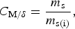
in a supermartensitic 13%Cr steel. The magnetisation saturation (m s) of small specimens of quenched and tempered steel was measured from the magnetisation curves obtained at room temperature with maximum applied field 1.5 T. The austenite volume fraction was calculated by the following equations:
The pitting corrosion resistance was evaluated by anodic polarisation tests in 3.5%NaCl solution at 22°C. Working electrodes were constructed with the specimen of 17Cr steel embedded in epoxy resin with a cooper wire connected for electric contact. The specimens were grinded with emery paper until grid 1200 and polished in 1 μm alumina paste. Saturated calomel electrode was used as reference and a platinum wire was used as counter electrode. The test was controlled by a potentiostat–galvanostat micro-AUTOLAB which varies the potential with controlled sweep rate and measures the current. Steady-state open circuit potential (E OCP) was read for 1 h. After this time, the potential increased with scan rate 1 mV s–1 until a potential correspondent to a current density of 10–3 A cm–2. At this time, the scanning was reverted to the cathodic direction, with the same rate. At least, three tests per heat treatment condition were carried out.
After the corrosion tests, the specimens were etched with Villela's reagent (90 mL distilled water, 10 mL HCl, 1 g picric acid) and observed in LOM and SEM.
Results and discussion
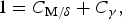
Figure 1a shows the ferritic–martensitic microstructure of the quenched material (specimen Q). The ferrite volume fraction of ferrite measured by quantitative metallography (ASTM E-5628) was 0.36 ± 0.03. Figure 1b–d shows the microstructure changes produced by tempering at 300, 500 and 650°C, respectively. It is observed the gradual decomposition of martensite (tempering reactions) and inter and some intragranular precipitation in the ferrite.
Microstructures of specimens: a Q; b QT300; c QT500; d QT650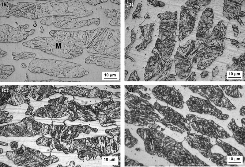
Figure 2 shows the XRD of specimens Q, QT650 and DT1. The as-quenched specimen shows coincident peaks of martensite and ferrite, and small reflections of austenite. The austenite peaks are increased with tempering at 650°C (QT650), suggesting that this tempering temperature is above the A 1 temperature of the steel. The steel is so-called triphasic, because contains ferrite, martensite and austenite. A further increase of the austenite reflections was observed in the double-tempered specimen DT1, as will discussed with magnetisation saturation results.
XRD from specimens Q, QT650 and DT1
Magnetisation saturation (m s), austenite volume fraction (calculated from equations (2)–(3)) and hardness
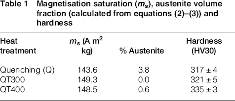
The lower hardness of specimens QT650 and DT1, in a comparison to other specimens, can be attributed to a combination of precipitates coarsening and austenite increase.
Figure 3 shows a typical polarisation curve from specimen Q (quenched). The main parameters obtained from the polarisation test are the open circuit (E OCP), the pitting (E Pit) and repassivation (E RP) potentials. The hysteresis area is also a qualitative result which gives some indication of the development of pits. If there is no hysteresis, the repassivation potential is close to the pitting or breakdown potential, indicating a low susceptibility to pit growth. This behaviour was not observed in this work, that is, the repassivation potentials were all very low and large hysteresis areas were seen in the cyclic polarisation curves, as shown in Fig. 3.
Curve obtained in the cyclic polarisation test of specimen Q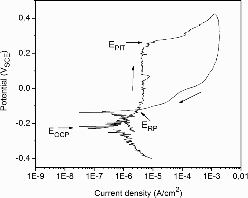
Figure 4 shows the variation of average values of E Pit and E OCP with the heat treatment. The difference E Pit – E OCP, which corresponds to the passivation range, is also plotted. Quenched and QT300 conditions presented equivalent pitting resistance parameters and this result could be explained by the similar composition of retained austenite and martensite phases. But, both pit potential and E Pit – E OCP slightly decrease with the increase of tempering temperature and time (DT1 condition). The decrease of pitting resistance can be related to two microstructural changes. First, Cr carbide precipitation is prone to happen even if the steel is stabilised.
12
Second, the formation of interlath and intergranular austenite in the domains of martensite islands may also create Cr-rich and Cr-depleted zones. The reversed austenite has high Ni, but low Cr, Mo and W contents when compared to the adjacent tempered martensite.
13
Average values of E Pit, E OCP and E Pit – E OCP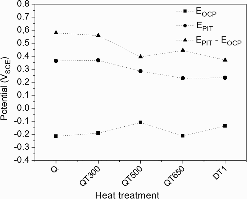
Figure 5 compares the pitting potentials of the 17%Cr steel studied in this work to a 15%Cr supermartensitic steel previously studied.
11
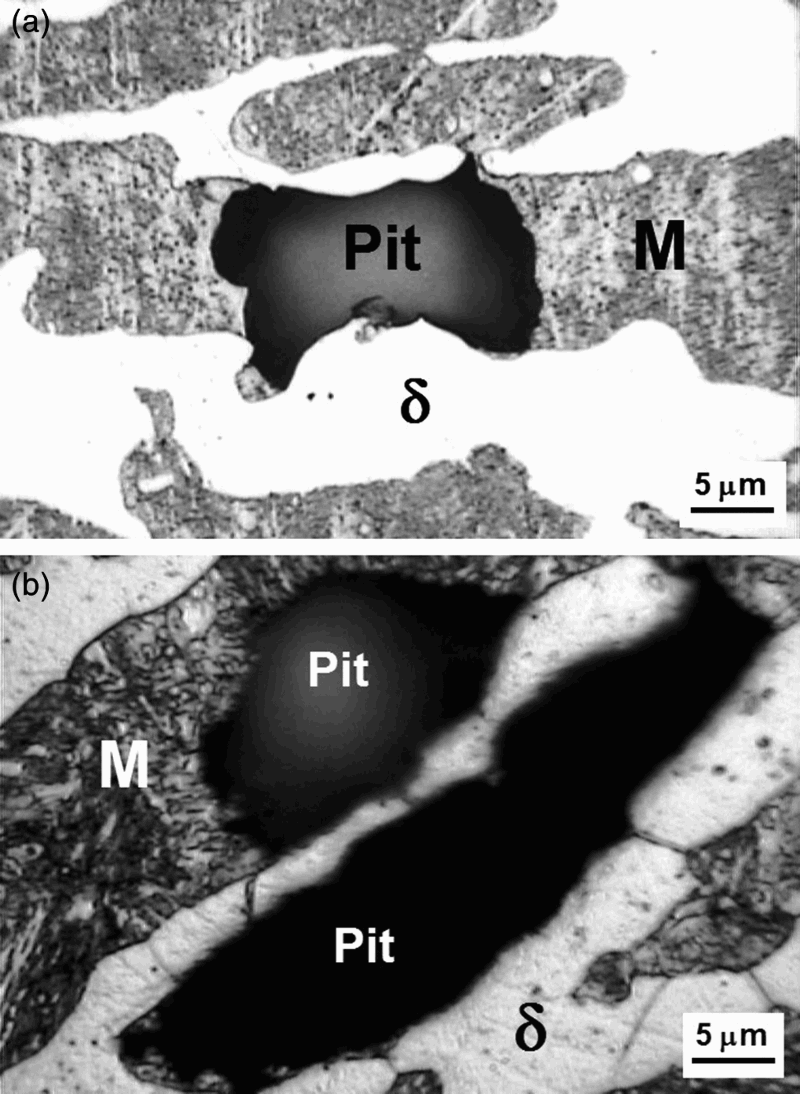
According to equation (1), the PRE numbers of these two alloys are 27.0 (17% Cr) and 21.7 (15% Cr). For the 17% Cr steel after Q and QT300 heat treatments, the mean value of E pit obtained is higher but the variability of E pit results is large. Higher tempering temperatures produce equivalent pitting potentials for both steels. Analysing the microstructure of the specimens after the pitting corrosion test, it was possible to observe a preferential pitting corrosion of the martensitic phase. The pits nucleated and grew into the martensitic island, being restricted to the domains of its phase. Figure 6a and
b
shows this behaviour in specimens Q and QT500, respectively, but it was observed in all heat treatment conditions.
Variation of pitting potential (E Pit) with heat treatment for steels 17% Cr (this work) and 15%Cr
11
Microstructure of specimens after the cyclic polarisation tests: a specimen Q; b QT500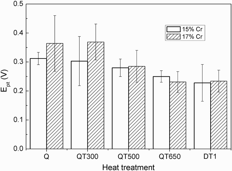
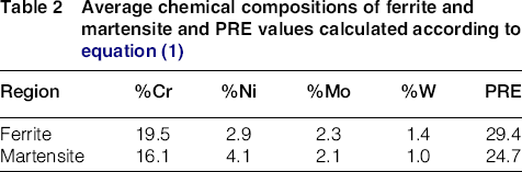
Since martensite is the product of the diffusional transformation of austenite, the martensite maintains the same chemical composition of its parent fcc phase. The soaking at 1000°C is performed in a biphasic field of austenite and ferrite. At this temperature, the elements partitioning is such that the ferrite phase concentrates more ferritising elements (Cr, Mo and W), while the austenite phase concentrates more Ni. As the result, the PRE value of ferrite must be higher than the PRE value of austenite and martensite which forms on cooling. Indeed, a semi-quantitative analysis by EDS (Table 2) conducted in four fields of specimen Q (Fig. 7) confirms that ferrite has higher Cr, Mo and W than martensite plus retained austenite.
Microstructure of specimen Q with fields selected for chemical analysis by EDS Average chemical compositions of ferrite and martensite and PRE values calculated according to equation (1)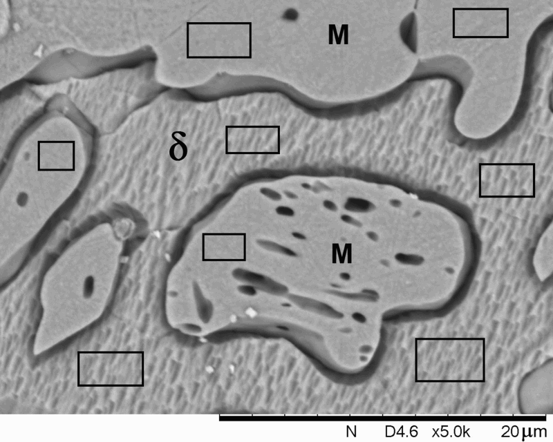
Conclusions
The 17%Cr steel studied in this work has a complex microstructure of ferrite, martensite (or tempered martensite) and austenite. The material undergoes some secondary hardening during tempering at 400 and 500°C and increase of austenite with tempering at 650°C and double tempering (670°C/2 h + 600°C/2 h). The increase of tempering temperature and time caused a slight decrease of the pitting potential in 3.5%NaCl solution. The pits nucleate and growth preferentially in the martensite islands, due to its lower Cr, Mo and W contents.
Footnotes
Acknowledgements
The authors would like to acknowledge the Brazilian Research agencies CAPES and CNPq for the financial support.