
Abstract
Fe–40 at.-% Al intermetallics with the addition of Li (1 and 3 at.-%) and Cu (3 and 5 at.-%) were produced using standard casting techniques. The oxidation behaviour was obtained using thermogravimetric analyses in an atmosphere of 99.99% oxygen at 800, 900, 1000, and 1100°C. The oxidation product layers on the top and cross-sectional views were characterised using SEM and energy-dispersive X-ray spectroscopy mapping. The different alumina phases can produce a double layer with different mechanical and chemical properties. The results showed that the addition of 1% Li assisted the activation of the oxide production at 1000 and 1100°C, while the rest of the third element additions slightly modified the oxidation resistance.
Introduction
Materials used in high-temperature processes (500-1200°C) require a high fusion point (≥1350°C), high strength, and high resistance to oxidation, carburisation, sulphidation, and hot corrosion [1,2]. They must also be easy to manufacture by conventional mechanical methods. The required oxidation resistance of high-temperature alloys depends on the application temperature. Many alloys can be applied at temperatures lower than 800°C, but only a few materials can be used at higher temperatures [2,3]. This threshold is due to the low resistance to oxidation, sulphidation, and other corrosion phenomena of the alloys at higher temperatures.
High-temperature oxidation can occur in different types of industrial equipment, such as steam-reforming tubes, nuclear processing reactors, gas turbine blades, waste incinerators, oil-fired boilers/superheaters, and similar systems [4,5]. The problems that occur at temperatures higher than 800°C could be resolved using alloys that are capable of producing protective oxide scales [6]. The most important oxide protective layers are of beryllium, chromium, silicon, and aluminium [6].
Beryllium oxide is not applied in industries because of its high toxicity [7]. Chromium oxide is not effective at these temperatures because it can be transformed into a volatile chromium compound in a humid atmosphere [8] and dissolved in chloride melts [9]. Silicon oxide could be a good option, but the alloying content to produce a homogeneous layer makes the material fragile [10] and its formation rate is very low [11]. Aluminium oxide could be the best option for several high-temperature applications [12].
Alloys with high aluminium contents, such as Fe3Al and FeAl intermetallics, can easily form protective layers at high temperature. These intermetallics have some of the features needed for high-temperature applications, including high strength, high corrosion resistance in molten salts, and high resistance to oxidation and sulphidation [1]. However, they have low ductility at room temperature [13]. Studies have characterised FeAl intermetallics and designed ways to improve the low ductility at room temperature via alloying [14–16], grain refinement [17], and modification of the traditional manufacturing processes [17]. Intermetallic filters have been successfully manufactured using power metallurgy techniques [18,19], although applying iron aluminides as coatings may be the best choice [20].
Third element additions to the iron aluminides have been done to improve the ductility at room temperature, such as Li, Ce, Ni, and Ag [14–16,21]. However, the effects of these additions on the oxidation, sulphidation, hot corrosion, and other high temperature issues have not been acquired at the same magnitude and rate as mechanical studies. An exception is, the effect of rare earth elements and their oxides on the oxidation behaviour of these intermetallics has been studied extensively [22 -29].
The minimum amount of aluminium to avoid internal oxidation and formation of iron oxide is 16-19 at.-% Al at 800 and 900°C [26,27]. Xu et al. [29] studied the effect of Y on the oxidation behaviour. They showed that cracking and spallation occurred at high temperature and during cooling of intermetallic FeAl, while these same phenomena occurred only during cooling for FeAl–Y alloy. Tortorelli and Natesan [28] found that FeAl had better oxidation resistance than iron-based and other alloys. The addition of chromium and oxygen-active elements (such as Y, Ce, Zr, La, B, Ti, and Hf) to Fe3Al improved the oxidation performance [28].
Oxides, such as Y2O3 and Al2O3, have been added to FeAl powder intermetallics to improve the mechanical properties [24], but it has been established that they could also improve the oxidation resistance [25]. Espinosa et al. [22] found that hot-sprayed FeAl with B and Al2O3 improved the oxidation resistance compared to the FeAl alloy alone. However, all the intermetallics had paralinear behaviour due to spalling, breaking down, and rehealing of the oxides. Grabke [23] reported two points of view about the effect of oxygen-active elements and their oxides on the oxidation behaviour. One is related to alloying elements, their incorporation in protective scales, and their role in the alumina phase stabilisation. Another is associated with the third element's effect on nucleation of the alumina phase, which Grabke [23] stated was the mechanism that improved the oxidation resistance.
The addition of Li, Cu, Ag, Ni has been done to improve the mechanical properties of a Fe–40 at.-% Al alloy [30]. In order to understand the effects of these additions on hot corrosion, research has been done in molten LiCl–KCl [4,5] and NaCl–KCl [31]. The effects of Li and Cu on the corrosion behaviour have been studied using polarisation curves [4], polarisation resistance [4], and electrochemical impedance spectroscopy [5] in a eutectic system of molten LiCl–KCl.
To summarise, Cu and Li additions to the Fe–40at.-% Al intermetallic have been shown to improve the strength [30], and their effects on the corrosion performance in molten chlorides have been characterised [4,5]. However, there are no studies on the effects of addition of these two elements on the oxidation behaviour of Fe–40 at.-% Al in rich oxygen atmospheres, so this work aims to characterise the oxidation behaviour.
Experimental procedure
Materials
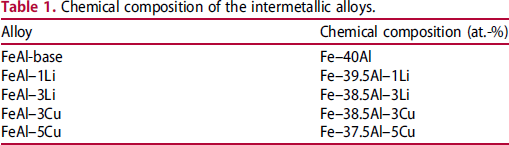
Chemical composition of the intermetallic alloys.
Sample preparation
The ingots were cut using electrospark wire cutting and a Buehler IsoMet® low-speed saw. For the oxidation testing, samples with a total area of 0.25 cm2 were acquired. The samples were then wet ground on 1200-grade SiC paper to clean and homogenise the surface conditions. The cross-sections were mounted in bakelite and ground with 600 and 1200 grade sandpapers. They were then polished with 9, 6, and 1 µm diamond paste.
SEM micrographs and EDX chemical analysis
For scanning electron microscopy, the samples were etched with Keller's reagent (2 mL HF (48%), 3 mL HCl, and 5 mL HNO3 in 190 mL H2O) for 15 or 20 s. The images were taken using secondary electrons (SE) in an Philips environmental scanning electron microscope (ESEM) model XL 30 at 20 kV. The chemical analysis of the elements was done with an energy-dispersive X-ray spectroscopy (EDX) microprobe coupled to the ESEM.
Thermogravimetric test and scanning electron microscopy
Mass gain experiments were done in a Perkin Elmer Pirys DIAMOND thermogravimetric analyzer with sensitivity in micrograms. The testing was done at 800, 900, 1000, and 1100°C for 72 h. The atmosphere was 99.993% oxygen with a flow rate of 12-15 mL min−1. Each sample had a surface area of 0.25 cm2. The heating rate of the oxidation experiments was 50°C min−1 in a nitrogen atmosphere. Once the desired temperature was reached, it was kept constant, and the oxygen atmosphere was introduced. The final cooling was done at 50°C min−1 in an oxygen environment. Thereafter, the alumina scale morphology on the alloy surfaces was obtained with SEM. The cross-sections of the scale that formed on the substrate were also observed through SEM, and EDX mapping was done to determine the locations of elements at the interface.
Results and discussion
Isothermal oxidation results and top views of the aluminium scales on the FeAl substrate
The type of alumina formed on the surface of FeAl intermetallics is related to the temperature according to the following sequence [32–36]:

The most protective alumina is α-Al2O3 due to its better adherence, compact layer formation, and lower growth rate compared to other types [37]. However, the other alumina phases can also be protective above 500°C [26,27,38,39]. The γ-alumina, δ-alumina, and θ-alumina show needle-like morphologies, while α-alumina shows hexagonal shape [26,27,38,39].
The oxidation kinetics at 800°C are shown in Figure 1(a). There were oxidation–spallation cycles, shown by the wavy mass gain curves. They are associated with the γ- and δ-alumina formation. These deviations from parabolic behaviour correspond to the existence of different alumina phases growing at the same time in the oxidation process. The cycles show maxima and minima that indicate the formation and spallation of an alumina layer. The alumina thickness reached a threshold, and then the layer is unpinned (around 10 hours in each cycle). The scale layers were extremely thin, and no specific morphology was observed using SEM.
Mass gain of the FeAl alloys as a function of time (a) at 800°C, (b) at 900°C, (c) at 1000°C, and (d) 1100°C.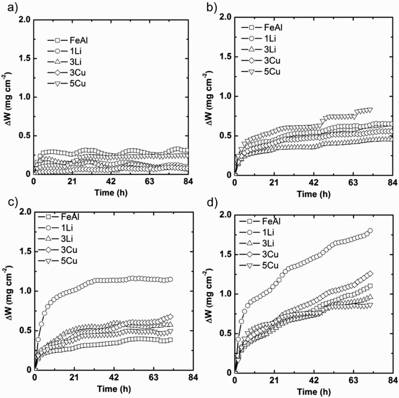
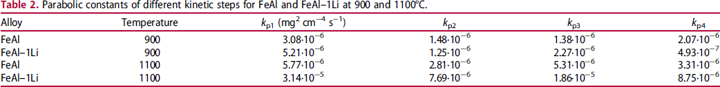
The kinetic behaviour at 900°C in Figure 1(b) was different from that at 800°C. The oxidation–spallation cycles were less evident, and the mass gain was higher at 900°C than at 800°C. These observations are related to the transformation from γ- and δ- to θ-alumina because θ-alumina has been obtained at temperatures below 950°C in FeAl alloys [21]. The parabolic slopes for FeAl and FeAl–1Li were obtained to examine the difference in alumina behaviour at 900°C (Table 2). In spite of the mass loss in each cycle at 800°C, the slope of the mass gain increases ≈7 h at 900°C. This behaviour has been observed previously [29], with the following explanation: (1) A first layer of alumina that may be a mixture of δ- and θ-alumina is established. (2) The alumina expands laterally, producing a lateral stress that causes slightly wavy scale. (3) At these wavy edges, an inner layer of the same kinds of alumina or even α-alumina can be formed. The outer and inner layers are shown in the centre of Figure 2(a). The detail of the outer layer with whisker morphology is shown in Figure 2(b). The presence of voids on the substrate, Figure 2(a), is very common and is due to aluminium and iron diffusion [23].
SE SEM images of the products on the surface of the intermetallic FeAl (a) and (b) at 900°C, (c) and (d) at 1000°C, (e) and (f) at 1100°C. Parabolic constants of different kinetic steps for FeAl and FeAl–1Li at 900 and 1100°C.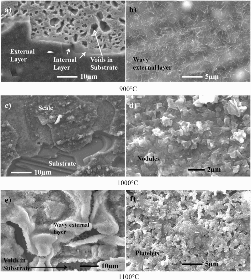
The kinetic results at 1000°C are presented in Figure 1(c). The change in oxidation behaviour is not significant between 1000 and 900°C, following a parabolic law in all the alloys (with small cycles of ≈21 h). However, the FeAl–1Li had a much higher mass gain of 1.2 mg cm−2, while the other alloys had gains under 0.6 mg cm−2. The α-alumina is stable at this temperature and is the best alumina phase for protecting the substrate. This is confirmed in Figure 2(c,d). The oxide layer on the FeAl alloy does not show needle-like morphology, but instead has a slightly wavy layer with some nodules.
The isothermal mass gain at 1100°C is shown in Figure 1(d). All the alloys acquired more mass at 1100°C than at the other temperatures. This can be confirmed in Figure 3(b), which shows step-like behaviour after approximately every 7 h for FeAl and 8 h for FeAl–1Li at 1100°C. However, the slope increase was very low for FeAl (Table 2), whereas the FeAl–1Li modification had cycles of high and low slopes (Table 2). These cycles were also evident in the other alloys (see Figure 1(d)). The stable alumina phase at 1100°C is α-alumina, but there are two stages in each cycle of growth, as described previously [29]: (1) Nucleation of α-alumina, (2) Formation of the wavy scale and voids at the scale/alloy interface, (3) Formation of the inner oxide layer, (4) Growth of the two-layered oxide scale, and (5) Oxidation after breakdown of the outer scale. The evidence for points (2), (3), and (4) is shown in Figure 2(e). High-buckle scale with voids was found in some parts. In addition, Figure 2(f) shows the coarsening and agglomeration of the α-alumina platelets found at 1000°C, which also supports point (4).
Square power of the mass gain (ΔW 2) vs. time for FeAl and FeAl–1Li (a) at 900 and (b) at 1100°C.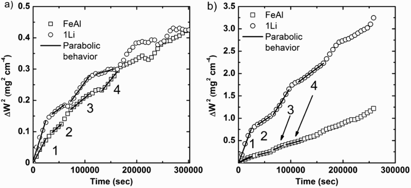
The results show that adding Cu and Li did not significantly modify the oxidation behaviour of the FeAl alloy, but 1 at.-% Li seemed to stabilise the θ-alumina at 1000°C and possible also at 1100°C, resulting in a high mass gain in the isothermal oxidation test. According to Grabke [23], the addition of reactive elements (e.g. Y, Ce, Zr, and Hf) should not affect the alumina transformation. Instead, the focus should be centred on the nucleation of the α-alumina due to the element addition. Adding 3 and 5 at.-% Cu and 3 at.-% Li did not modify the α-alumina nucleation. These alumina phases were produced at temperatures examined in other research on hot corrosion [32–36]. The addition of 1 at.-% Li could stabilise the θ-alumina or modify the α-alumina nucleation in some way.
Parabolic oxidation behaviour
The behaviour of all the alloys was not shown in this section because they were very similar (FeAl, FeAl–3Li, FeAl–3Cu, and FeAl–5Cu). Attention was paid to FeAl and FeAl–1Li as these were the alloys with the most different results. Several types of behaviours have been observed in oxidation kinetics at high temperature, such as linear, exponential, and parabolic behaviours [40]. The kinetic may be a combination of simpler behaviour, such as paralinear behaviour, which is a combination of parabolic and linear behaviour [41]. The parabolic result is the most common kinetic behaviour of layer products that can cover and protect the entire metallic surface, and can be described by equation (2) [29]:
Most of the alloys had parabolic cycles with a defined time. Figure 3 shows FeAl and FeAl–1Li had similar cycles at 900°C. However, they were shorter for FeAl than for FeAl–1Li at 1100°C. The magnitude of the kp was around the same order of magnitude at 800°C for both materials, but it showed a smaller value in the second stage in the parabolic behaviour for FeAl–1Li. On the other hand, FeAl–1Li showed a high increment in both stages of a parabolic cycle than FeAl.
SEM of oxide layers and substrate interface in cross-section
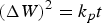
The SE and BSE SEM results are shown in Figure 4(a,b). The SE micrograph shows an irregular surface with oxide section in different areas, but not completely along the interface. The BSE SEM image shows a brilliant substrate because iron and aluminium were in this area. The product layer is medium dark because aluminium and oxygen are lighter than iron. The upper area is the darkest because carbon is the main component of the bakelite.
(a) SE SEM image of FeAl at 1100°C, (b) BSE SEM image of the zoom area in (a), results of the EDX maps for iron (c), aluminium (d), and oxygen (e).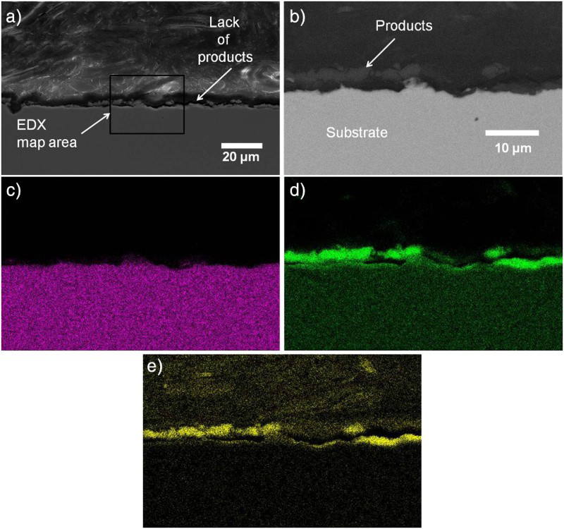
The EDX map results for iron, aluminium, and oxygen are presented in Figure 4(c,d,e), respectively. Iron was found in the substrate, aluminium was acquired in the substrate and oxide product layer, in agreement with the BSE image. The oxygen is concentrated in the oxidation products where aluminium was found in higher quantities, which is associated with the formation of Al2O3. There was a decrement in the concentration of iron and an increment of aluminium in some subsurface spots of the interface substrate–oxidation products, as seen in Figure 4.
FeAl–1Li had the highest mass gain, which drew interest of its interface characterisation. The SE SEM micrograph and the EDX maps of iron, aluminium, and oxygen are shown in Figure 5. Importantly, the interface was very smooth along the entire sample boundary. The upper part of Figure 5(a) shows the bakelite used to mount the sample. The lower part is the FeAl–1Li intermetallic substrate, and the oxidation layers are in the middle of the image. The middle area shows two tones on the substrate. One is clearly a layer attached to the substrate, and the other is an empty space that was filled with metal oxides. The grinding and polishing process detached the upper part of the product layer, which had poorer mechanical properties than the lower layer.
(a) SE SEM image of FeAl–1Li at 1100°C, results of EDX maps for (b) iron, (c) aluminium, and (d) oxygen.
The EDX map results are presented in Figure 5(b–d). Iron was present only in the substrate. Aluminium appeared in the substrate and the oxides attached to the substrate, and in the remains of the upper product layer. Oxygen was identified in the area where Al was concentrated in the oxidation products (the lower attached layer and the remains of the upper layer). The associated compound is Al2O3.
The cross-section of FeAl, FeAl–3Cu, and FeAl–1Li intermetallic alloys was compared. Figure 6 shows the micrograph and EDX map analysis results for FeAl–3Cu. The substrate showed a rough interface with the oxide along the entire length of the sample. In Figure 6(a), the oxidation products can be seen in the centre of the micrograph, and there was no delamination of the upper layer as with the Li sample. The oxide layer was detached from the substrate at the interface around the sample, and it was totally lost in some areas, as indicated in Figures 4 and 6. The X-ray map results are shown in Figure 6(b–d). Iron was found only in the substrate. The presence of aluminium was seen in the substrate, but the concentration was a little higher in subsurface spots below the product and in the product layer itself. Oxygen was in almost the same areas as the aluminium. Copper was found only in the substrate. The presence of aluminium and oxygen in the same area is linked to Al2O3.
(a) SE SEM image of FeAl–3Cu at 1100°C, results of EDX maps for (b) iron, (c) aluminium, (d) oxygen, and (e) copper.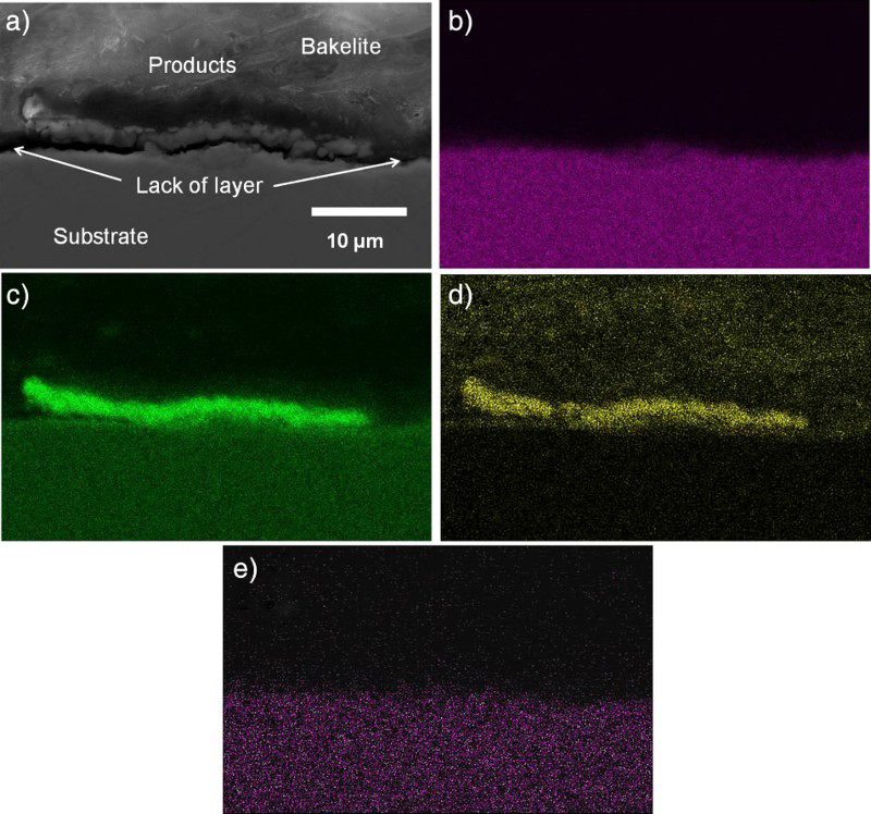
The presence of oxygen and aluminium in subsurface areas in Figures 4 and 6 can be related to the mechanism mentioned in Section ‘Isothermal oxidation results and top views of the aluminium scales on the FeAl substrate’. This supports the idea that the scale could be made up of two sub-layers: an external one that is very rough, and an inner one that is compact with good adherence to the substrate. This cycle of detaching the upper later, transformation from the inner layer into the external layer, and the creation of a new inner layer would be repeated several times, as can be seen in Figure 1 for different temperatures.
The oxides could be separated in the outer and inner layers. However, the outer layer in the FeAl and FeAl–3Cu had better mechanical properties than the one obtained in the FeAl–1Li. From Figure 4(a), 5(a), and 6(a), the thickness of the product layer was ≈2.5 µm for FeAl, ≈ 2 µm for FeAl–3Cu, and ≈5.5 µm for FeAl–1Li. The estimation of these thicknesses was done including the empty space of the detached upper layer in Figure 5.
These thicknesses are significantly different, which supports the results obtained in the mass gain experiments (Figure 1(d)). Lithium addition produced a significant mass gain in relation to the other intermetallic alloys. This result could be explained by the different influences of the additional elements (copper or lithium) on the alumina phase transformation or their influence on the nucleation and growth of α-Al2O3 [23]. The type of alumina observed strongly depended on the testing temperature [32–36]. It also seems to be affected by the addition of elements like Y, Ce, Zr, La, and others (oxygen-active elements) [23,28,29]. In addition, some oxides included in the iron aluminide intermetallic structure by different techniques (e.g. thermal spray coating techniques) could affect the oxidation resistance, like Y2O3 and Al2O3 [22,25]. Grabke [23] claimed that the discussion has to be based on the effect of the third element on the α-Al2O3 nucleation since the oxygen-active elements were not found inside the oxidation products and so cannot affect the alumina phase transformation. The current results for FeAl–3Cu could support the idea of influencing the α-Al2O3 nucleation. The copper was found only in the substrate, and not in the product layer. The addition of copper did not significantly modify the oxidation behaviour because the nucleation of any kind of alumina was not affected.
The case of the intermetallics with lithium addition cannot be shown. However, the active oxide elements did not play a role in retardation of the alumina transformation, since they did not enter into the oxidation layer, or the quantity is negligible [23]. These oxygen-active elements and their oxide dispersion in the aluminide intermetallic alloys modified the α-Al2O3 nucleation. In fact, the way that the active-oxygen elements change the nucleation rate is that they are oxidised too, even faster than the aluminium. These oxides that act as nuclei for the α-Al2O3, which, in turn, promotes the rapid kinetics of α-Al2O3 formation compared to other alumina types. This can result in a better oxidation resistance due to α-Al2O3.
Li as well as copper was not incorporated in the oxidation products. Instead, the 1 at.-% Li modified the α-Al2O3 nucleation in some way. The nucleation was retarded, which permitted the growth of θ-Al2O3. The θ-Al2O3 layer was, therefore, thicker than for the rest of the alloys at 1000 and 1100°C. The external layer was detached by the simple preparation sample process, but the addition of Li decreased the spallation during cooling from high temperature to room temperature.
Conclusions
The addition of Cu and Li improved the oxidation resistance at 800°C, and the alumina phases are δ- and γ-alumina at 800°C. The behaviour of oxidation was improved slightly with the addition of 3 at.-% Li and 3 at.-% Cu at 900°C. The products were γ- and θ-alumina at this temperature. Furthermore, α-alumina was wavy at some points similar to the inner oxide layer. As a result, the oxidation showed cycles with two different parabolic constants.
The addition increased the oxidation resistance at 1000°C for all alloys compared to the FeAl-base alloy. The stable phase was the α-alumina, but FeAl–1 at.-% Li formed θ-alumina. All of the alloys had increased mass gain at 1100°C compared to the lower temperatures. An α-alumina scale was found in all the alloys, but at 1100°C the scale was highly wavy, and some areas of the scale separated from the substrate. The FeAl–1 at.-% Li had the highest mass gain because the lithium addition either stabilised the θ-alumina layer or created nuclei that enhanced the θ-alumina growth.
Footnotes
Acknowledgements
Dr Jesus Barraza thanks CONACYT for the financial support in his postdoctoral internship at Texas A&M University.
Disclosure statement
No potential conflict of interest was reported by the authors.