
Abstract
To investigate the influence of nitrogen on structure and corrosion resistance of Cr15 super martensitic stainless steels (SMSS), two types (N-free and N-0.12%) of specimens were quenched at 1050°C and tempered at different temperatures, and then, optical microscope, transmission electron microscopy, X-ray diffraction, potentiodynamic polarisation, immersion experiments and Kelvin Probe Force Microscope were used to characterize its microstructures and corrosion properties. The experimental results show that the microstructure in the N-free Cr15 super martensitic stainless steel is a biphasic tissue with alternating martensite and austenite distribution while quenched at 1050°C and tempered between 600 and 700°C. The nitrogen addition increases the content of austenite, and changes the austenite morphology significantly into the coarse block and strip distribution. What's more, micro-galvanic corrosion is formed between austenite and martensite, which deteriorates the corrosion resistance of the SMSS.
Introduction
Super martensitic stainless steel is a kind of ultra-low carbon martensite stainless steel, which not only maintains the strength, hardness and toughness of the corresponding traditional martensitic stainless steel, but also has better corrosion resistance and welding performance [1–3]. So in some areas of high corrosion resistance and welding performance requirements, such as electric power and oil-and-gas fields, super martensitic stainless steel can emerge from many materials, replacing the traditional stainless steel gradually and become the new application materials [4]. However, during heat treatments, high chromium equivalent (Creq) or component segregation leads to a certain amount of δ-ferrite, which is difficult to eliminate unless a high-temperature diffusion annealing is carried out [5,6]. As a harmful phase, δ-ferrite has adverse effects on the strength, thermoplastic and corrosion resistance of super martensitic stainless steels (SMSS), such as brittle fracture, surface cracking or reduction of corrosion resistance [7,8]. Although austenitic formation elements of Ni and C added can effectively reduce the δ-ferrite [9], Ni as an expensive alloying elements will greatly increase the cost of SMSS [10], and the increase of C will bring the reduction of corrosion resistance, weldability and ductility [11], do more harm than good. Whereas nitrogen, an austenite-stabilising element, not only can effectively reduce the formation of the δ-ferrite [10], but also can change its shape into short rod and island [12], which can reduce its bad effects. Therefore, it may be a good choice to add nitrogen to the SMSS to reduce the formation and damage of the δ-ferrite.
At the same time, nitrogen, as a cheap strengthening element, can improve the strength of martensite stainless steel by means of solid solution strengthening, precipitation strengthening and fine crystal strengthening [13–15]. What's more, nitrogen also has a certain influence on corrosion resistance [15–17]. In the pitting resistance equivalent number [18] (PREN = %Cr + 3.3%Mo + 30%N), nitrogen plays a positive role in improving pitting potential of stainless steel. Some researches show that nitrogen can improve the stability of passive film of stainless steel [19]. Meanwhile, it can reduce the activity of Cr and inhibit the precipitation of carbides in the grain boundaries, thus reducing the depletion of Cr [20,21]. However, these effects are limited to nitrogen precipitated in the form of small precipitates or in a solid solution state. Nitrogen is still an important austenite-forming element, and its ability to expand and stabilize austenite phase area is about 25 times that of Ni element [22], playing a decisive role in martensite phase transformation. Studies [23,24] have shown that nitrogen significantly increased the austenite content in the process of heat treatment in SMSS. However, little research has been done to SMSS in the change of its corrosion resistance which results from phase transformation caused by the addition of nitrogen. Therefore, in the paper, a certain amount of nitrogen was added to study the effect of nitrogen on the microstructure and corrosion resistance of the Cr15 super martensite stainless steel.
Material and experimental procedure
Material and heat treatment
Chemical composition of tested steel (wt-%).

Microstructure and morphology characterisation
After grinding and polishing, the specimens with dimensions of 10*10*12 mm were etched by 10 gFeCl3 + 130 mLHCl + 120 mLH2O solution. The microstructures of specimens were observed using an optical microscope. In order to verify the phase structure, X-ray diffraction (XRD) analyses were carried out. For transmission electron microscopy (TEM) characterisation, thin foils with dimensions of 10*10*0.2 mm were cut from the heat-treated specimens, ground to 50 µm (thickness) with SiC papers and twin-jet polished. Then, TEM was used to analyse the microstructures and chemical compositions of the heat-treated specimens.
Electrochemical measurements
The equipment for electrochemical experiments is the VersaSTAT 3. Potentiodynamic polarisation curve was measured by classical three-electrode system. The working electrodes (WEs) is the heat-treated specimens with 1 cm2 exposed area. A platinum electrode and a saturated calomel electrode were used as the counter electrode (CE) and the reference electrode (RE), respectively. The 3.5% NaCl aqueous solution was used in this study, and the experimental temperature was stabilized at 25 ± 1°C with a water bath.
Immersion test
For immersion test, thin discs with dimensions of φ30*5 mm were cut from the heat-treated specimens, ground with SiC papers (to 800 grit), rinsed with deionized water, degreased in ethanol, and finally immersed in 6%FeCl3 aqueous solution for 48 h. The experimental temperature was stabilized at 22 ± 1°C with a water bath. Then, washing away the corrosion product and measuring the weight loss is done. Finally, the corrosion surface is observed by an optical microscope.
Surface potential measurement
The potential of the specimen surface was measured by Kelvin Probe Force Microscope (KPFM). The metallographic examination of the specimen was conducted to determine its phase distribution before KPFM experiment. The area where the potential change is expected to be measured is marked. Then the surface is ground and polished, and finally, the surface potential at the mark is measured by KPFM. So, it's convenient to determine the phase distribution of the area where the potential is measured.
Results
Microstructure at different tempering temperatures
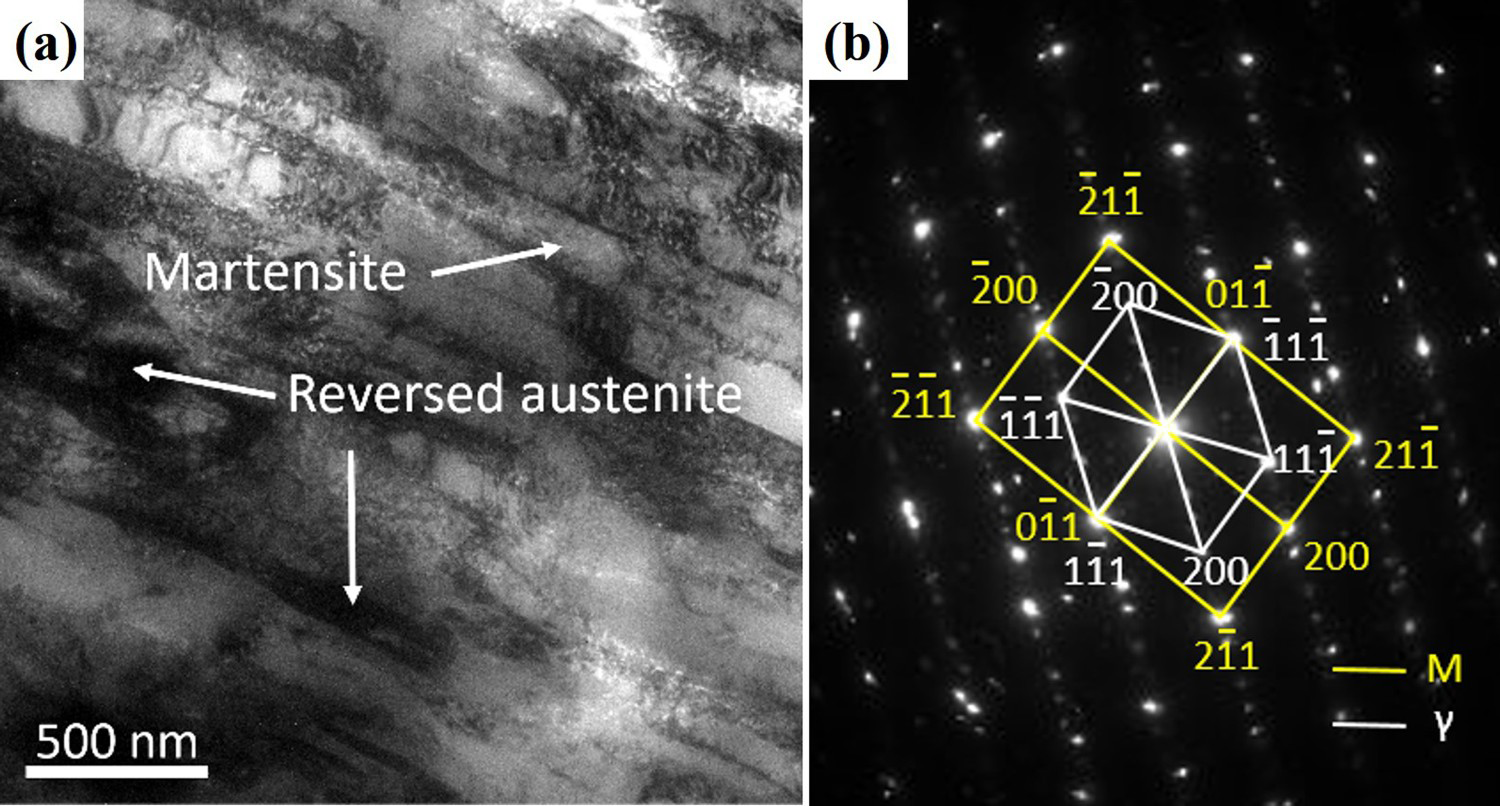
The metallographic structure of the two types of specimens is shown in Figure 1. The pictures show that the microstructure of the heat-treated steel is basically tempered martensite. For the steel No.1, when the tempering temperature comes to 600°C which is not high enough, the microstructure still retains the quenched martensite morphology. When the temperature rises to 650°C, the quenched martensite decomposes into fine tempered martensite, and some martensite begins to transform into reversed austenite. As the tempering temperature continues to rise, the effect of martensite refinement becomes more obvious. The results from XRD analyses (Figure 2) show that as the tempering temperature rises to 750°C, the stability of the reversed austenite (N-free specimen) begins to decrease, and most of the austenite translate into martensite after cooling. Figure 3 is the TEM images of steel No.1 after tempering at 700°C. As seen in Figure 3, the width of lath martensite is between 200 and 400 nm, and the austenite of strip or film are distributed at the boundaries of martensite. But austenite in some areas are in clumps. Therefore, the microstructure in the steel is a biphasic tissue with alternating martensite and austenite distribution.
Metallographic structure of two types of specimens tempered at different temperatures: (a) No.1. 600°C; (b) No.1. 650°C; (c) No.1. 700°C; (d) No.1. 750°C; (e) No.2. 600°C; (f) No.2. 650°C; (g) No.2. 700°C; (h) No.2. 750°C; XRD results for two types of specimens with different heat treatment. (a) XRD spectra, (b) Austenite content. TEM results: (a) TEM microstructure of steel No.1 tempered at 700°C, (b) Selected area electron diffraction pattern of steel No.1.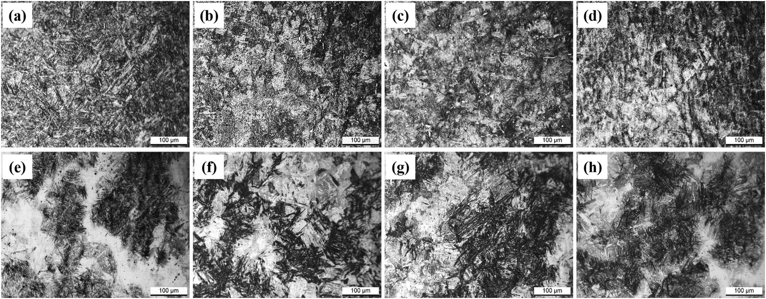
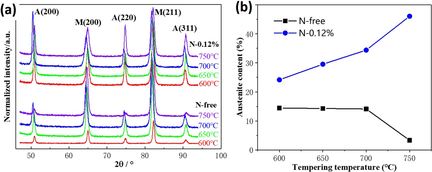
The result of XRD analyses (Figure 2) shows that the austenite content of N-0.12%-steel (steel No.2) is above 25%, while that of N-free steel (steel No.1) is less than 20%. This indicates that nitrogen is austenite stabilized element, which makes more austenite formed in steel. Moreover, the morphology and distribution of austenite in steel No.2 are distinctly different from those of steel No.1. The austenite in steel No.2 no longer distributes at the boundary of martensite, but is distributed in martensite matrix in massive or strip shape (Figure 1). The microstructure of N-12% steel is distinctly biphasic.
Corrosion
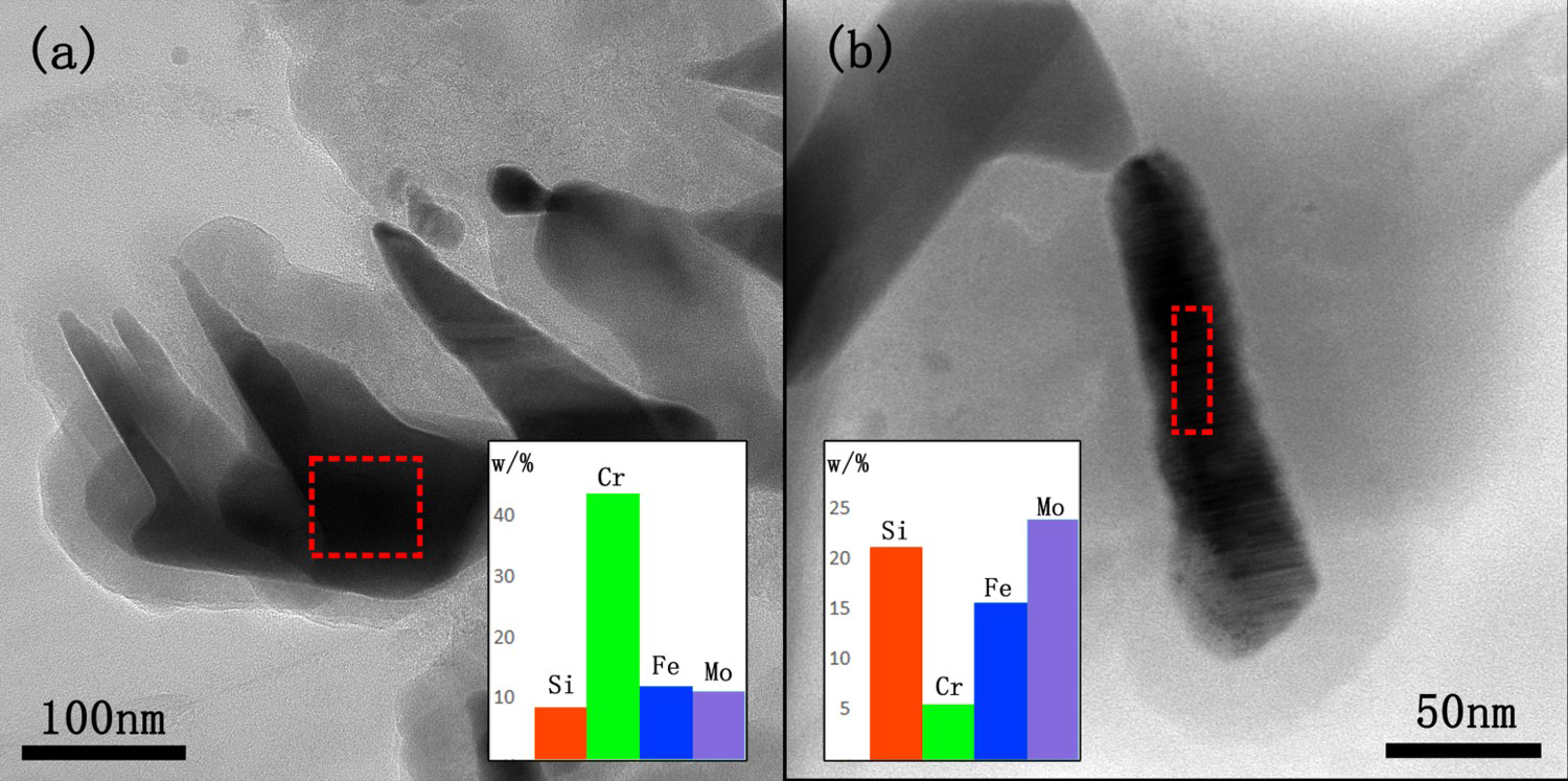
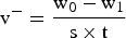
The potentiodynamic polarisation results of steel No. 1 and No. 2 at different tempering temperatures are shown in Figure 4. It can be seen from Figure 4(a,b) that the polarisation curves have obvious passivation zones, which indicate that the specimens form a dense passive film in 3.5%NaCl solution. With increasing tempering temperature from 600°C to 700°C, the pitting potential of steel No.1 reduced from 281.5 to 218.6 mV, but rising to 278.8 mV as the tempering temperature comes to 750°C. During the tempering process, the contents of Cr and Mo adjacent to the Cr/Mo-rich carbides were reduced by precipitation of Cr, Mo, resulting in Cr/Mo depleted zone. The anode current density on the surface of the depleted zone is higher than that on the surface of the substrate, and chloridion will be enriched in a place where the anode current density is high. When the concentration of chloridion attains to a certain value, the passivation film will be dissolved and the pitting source is formed, thus reducing the corrosion resistance of the steel [25]. The morphology of the precipitates is shown in Figure 5. Energy Dispersive Spectrometer (EDS) measurements show that the precipitates are indeed rich in alloying elements of Cr, Mn or Si. The higher the tempering temperature, the more precipitated phases. When the tempering temperature rises to 750°C, the increase in pitting potential is related to the decrease of reverse austenite. The formation of reverse austenite during tempering leads to non-uniform microstructure, and austenite becomes a cathodic phase in the corrosion, and forms micro-galvanic corrosion with the martensitic matrix. This will be confirmed in the following experiments. The stability of austenite is greatly reduced when it is tempered at 750°C and then converted to secondary martensite after air-cooling. Therefore, the austenite content is greatly reduced as shown in Figure 2(b). As cathode/anode area ratio increases, the galvanic effect increases [26,27]. Zhang [28] has deduced the formula of the corrosion speed of steel couple as follows:
Potentiodynamic polarisation results: (a) Curves of steel No.1, (b) Curves of steel No.2, (c) Pitting potential. Precipitates of steel No.1 tempered at 700°C.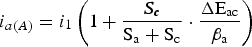
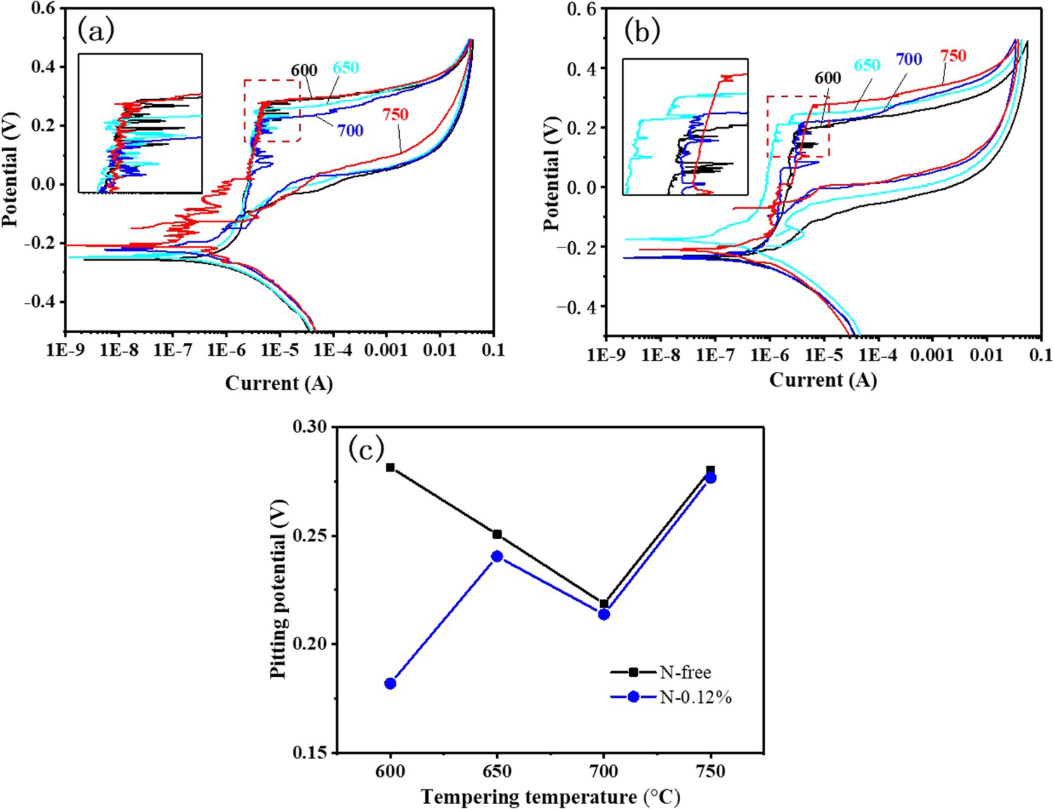
It can be seen from the formula that the corrosion current density of the anode increases with the increment of the proportion of cathode area to the total area. So, reduction of cathodic phase would lead to corrosion current decrease, thereby reduce the galvanic corrosion. In the polarisation experiment, the potential is going up but before the trans-passivation potential, the passivation film on the metal surface is partially destroyed by the galvanic corrosion between the austenite phase and the martensite phase. At the break of the passivation film, the metal surface is undergoing anodic dissolution with a high anode current density. The total anode current of the metal electrode increases sharply at this time. In this case, the passivation zone of the curve is greatly shortened. When the potential of the metal electrode reaches the critical potential (
In Figure 4(c), the pitting potential of steel No.2 is lower than that of steel No.1, especially when the tempering temperature is low. This preliminarily shows that the addition of nitrogen reduces the corrosion resistance of the test steel. In order to further compare the corrosion resistance of steel No.1 and steel No. 2, a soaking experiment was conducted and the results are shown in Figures 6 and 7.
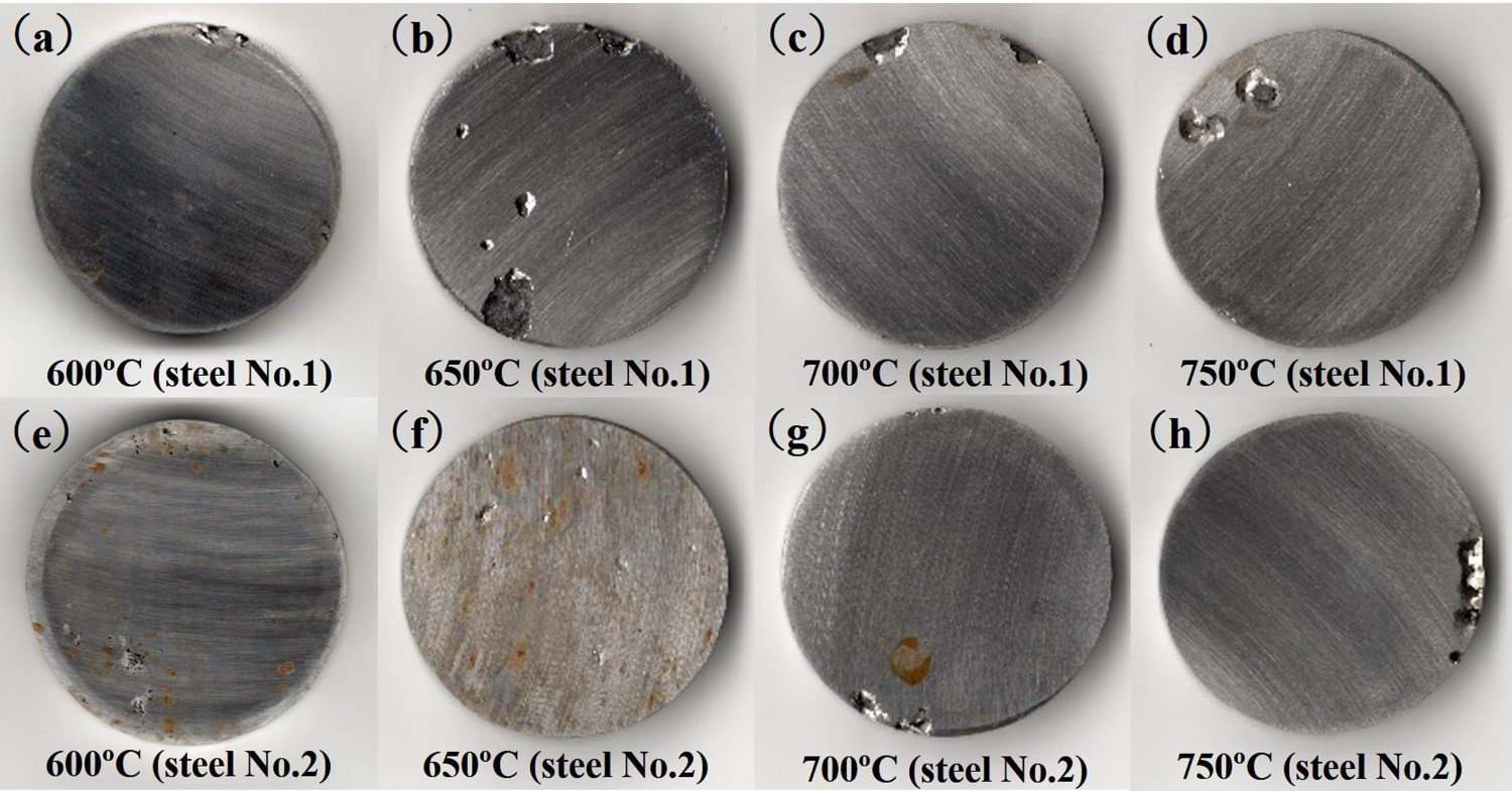
The surface morphology of 700°C tempered specimens soaked in 0.16%HCl + 6%FeCl3 solution for 24 h: (a) Steel No.1, (b) Steel No.2. Macroscopic morphology of specimens with different tempering temperatures soaked in 6%FeCl3 solution for 48 h.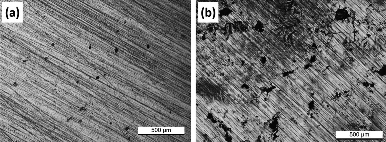

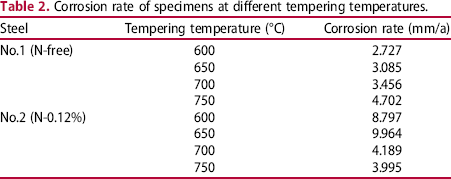
Corrosion rate of specimens at different tempering temperatures.
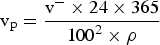
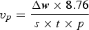
Combined with formula (2), (3) and (4), we get formula (5):
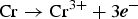
In order to further study the mechanism of nitrogen reducing the corrosion resistance of Cr15 super martensitic stainless steel, the specimen in Figure 6(b) was polished and eroded with the metallographic etchant. The surface topography is shown in Figure 8(a,b). The distribution of pits is basically concentrated in martensite (the black phase in the images), and there are a few corroded holes in the austenite (the white phase). This result proves that martensite has higher corrosion sensitivity than austenite, and pitting corrosion occurs more easily on martensite. This may be caused by the formation of a galvanic couple between austenite and martensite. Galvanic corrosion occurs between them, and martensite is preferentially etched as the anode. The condition of galvanic corrosion is that there is a certain difference of potential between them. In order to confirm this point, the KPFM was used to measure the surface potential of a sample of steel No.2 tempered at 700°C. The results, in Figure 8(c,d), are shown that the potential of martensite is obviously lower than that of austenite, and the gap is close to 100 mV. Combining the distribution of pits with the KPFM result, it can be considered that martensite and austenite form micro-galvanic corrosion in the 15Cr SMSS containing 0.12% nitrogen. The micro-galvanic corrosion further induces pitting. A schematic illustration of the corrosion is shown in Figure 9. The austenite with higher potential is used as the cathode, while the lower potential martensite is used as the anode. The corrosion cell formed between those two phases makes the anodic current density of the martensitic the boundary near to austenite higher than the average anode current density around it. Chloridion will be enriched in this position. When the concentration of chloridion attains to a certain value, the passivation film will be dissolved, making this site for pitting nucleation [25]. When the pits are formed, the electrochemical conditions inside the holes will change significantly. The metal surface inside the pit is in the active state and the anodic dissolution occurs [29]. The reactions are:
Distribution of pits and the surface potential of steel No.2 (N-0.12%): (a) and (b) Pits distribution, (c) Microstructure, (d) Surface potential. Schematic illustration of the corrosion.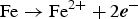


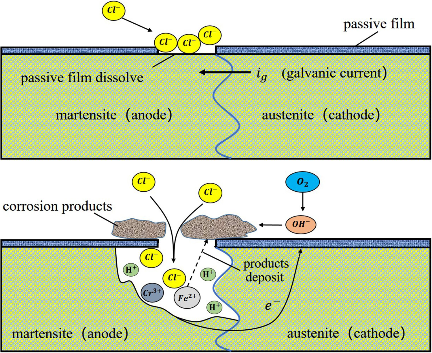
FeCl3 solution is neutral or weakly acidic, so the cathode reaction outside the pit is:


Corrosion products cover the port of the pit, blocking ions, except chloridion, from entering and leaving. So that, an occluding cell forms [30]. The metal cation produced by the anode reaction in the pit is hydrolysed.

Discussion
The addition of nitrogen, as a strong austenite-stabilising element, significantly increases the content of austenite which is the cathode phase in the steel. This increment promotes the galvanic corrosion, thereby reducing the corrosion resistance of the steel. Therefore, the addition of nitrogen has a certain negative effect on the corrosion resistance of Cr15 super martensitic stainless steel. It is worth mentioning that there are also two phases of austenite and ferrite in the duplex stainless steel, but the biphasic phases do not deteriorate the local corrosion. On the contrary, the galvanic effect between them, would promote the modifications of chemical composition and semiconductive property of the passive film and therefore the enhancement of the corrosion resistance of the duplex stainless steel [31]. Therefore, to improve the corrosion resistance of super martensitic stainless steels by adding nitrogen, besides ensuring that nitrogen exist in solid solution or in the form of fine precipitates, the content and morphology of the austenite should be made sure that it does not change significantly. So, when nitrogen is added, the heat treatment process should be appropriately adjusted to reduce the excessive formation of austenite, or reduce the content of austenite-forming elements such as C and Ni in stainless steel, that is to say, substitute N for C or Ni.
Conclusions
Microstructure of the heat treatment Cr15 super martensite stainless steel mainly contains martensite and austenite, which distribute alternately. The addition of nitrogen increases the content of austenite and changes the morphology and distribution of austenite distinctly. And it becomes distributed in martensite matrix in massive or strip shape. Austenite has an important influence on the corrosion resistance of Cr15 super martensitic stainless steel. The coarse austenite acts as a cathode and forms micro-galvanic corrosion with martensite. The addition of nitrogen significantly increases the content of austenite. This increment expands cathode area and promotes the galvanic corrosion, thereby reducing the corrosion resistance of the Cr15 super martensitic stainless steel.
Footnotes
Disclosure statement
No potential conflict of interest was reported by the authors.