
Abstract
This paper presents a state-of-the-art view and some fundamental considerations on developing and utilising corrosion probes (or sensors) as sensing components in infrastructural health monitoring (IHM) systems. Practical cases are presented to illustrate major challenges and recent progresses in corrosion probe research, with particular focus on cases of addressing some critical challenges by designing corrosion probes based on electrochemically integrated multi-electrode arrays. It is shown that at present successful application of corrosion probes for IHM in complex and dynamic environmental conditions has been limited, and the validity of corrosion monitoring data is often left unexamined. It is suggested that major advancements have to be made in the probe design, installation, and data analytics in order to significantly enhance the effectiveness and reliability of corrosion probe application in IHM systems.
Keywords
Introduction
Infrastructural health monitoring (IHM) refers to in situ, continuous or regular measurement of key structural and environmental parameters from industrial and civil infrastructures such as underground and offshore pipelines for the purpose of warning impending abnormal infrastructural health conditions at an early stage and giving maintenance and rehabilitation advices [1–5]. A typical IHM system includes three major components: sensors or probes for data acquisition; a data transmission, storage, data mining system for feature extraction; and a health evaluation system for decision-making based on identified data features, usually in combination with predictive models [2]. IHM was originated mainly from major bridges, probably due to high awareness of the economic and social effects of ageing, deterioration and extreme events on such important civil infrastructures [3,4]. Over the past several decades, many specialised sensors or probes, such as fibre optic sensors, piezoelectric actuators, vibration sensors, leakage detecting sensors, pressure, flow, and seismic sensors and corrosion detection sensors/probes have been developed and utilised in many infrastructural systems for monitoring a range of structural and environmental parameters such as stress, displacement, wind speed, temperature, corrosion rates etc. In the case of long-span bridges, for instance, major concerns are often wind load, temperature, traffic load, geometric configuration, strain, and global dynamic characteristics; therefore, sensors selected to be installed on bridges are often anemometers, temperature, strain and accelerometer sensors [4,5]. Corrosion is commonly not considered as a principal concern for this type of conventional infrastructures.
For infrastructures exposed to complex and highly corrosive environmental conditions such as underground pipelines and offshore oil and gas infrastructures; however, corrosion is a major concern and, therefore, corrosion inspection and monitoring are considered to be critical for ensuring the safety, durability and reliability of these infrastructures. Indeed corrosion has been a significant structural integrity concern affecting the safety and reliability of many critical industrial and civil infrastructures including piers and ports, water, wastewater and sewer systems, oil and gas production, transportation and processing facilities. Corrosion-induced catastrophic infrastructure failures have been widely reported in the literature. For example, localised corrosion-induced underground pipeline explosion in the eastern Chinese city of Qingdao claimed 62 lives and huge economic losses [6]. It was followed by a similar explosion in Taiwan that caused 32 deaths and 321 injuries [7]. The localised corrosion that caused gas pipeline explosion at Varanus Island facility in Western Australia was estimated to cost the state's economy between $1.8 billion and $6.7 billion [8]. These are just a few reported cases among an enormous amount of infrastructure incidents in the world, for instance, in the United States there are approximately 240,000 water main breaks every year and corrosion contributed to many of them [9]. These incidents clearly indicate the extreme consequences of infrastructural failure that is often due to the corrosion of high-risk hidden structural components in an unanticipated manner [1 -8]. The lack of corrosion data from ‘invisible’ underground infrastructures is a major issue that significantly impedes the timely maintenance of infrastructural health. It has been recognised for a long time that corrosion data are critical for developing high-quality infrastructural management and maintenance strategies, especially for ‘hidden’ and submerged infrastructures. This need is particularly apparent when the operational life of aged infrastructures is extended beyond their design life. For this reason, the development of accurate and robust probes and sensors for acquiring corrosion data has been listed as a critical need for infrastructure transformational research [9] and a grand challenge for corrosion research by the Committee on Research Opportunities in Corrosion Science and Engineering, US National Research Council [10].
Unfortunately at present, the reality is that successful application of corrosion monitoring probes in complex infrastructural systems such as underground pipelines has been rather limited, despite the fact that major effort has been made to develop corrosion probes worldwide. This paper intends to explain this situation by presenting a critical overview of corrosion probe techniques, including the identification of issues and weaknesses of corrosion probe applications in highly complex, resistive and inhomogeneous media such as underground pipeline conditions, and the examination of principles and limitations of major forms of corrosion probes. Practical cases that the author has significant first-hand experiences are used to illustrate critical challenges and recent progresses in corrosion probes technologies, with particular focus on cases of designing and developing corrosion probes based on electrochemically integrated multi-electrode arrays for pipeline applications.
Overview of corrosion data acquisition from infrastructures
Traditionally the most common approaches to collecting corrosion data from hidden infrastructures, such as buried pipelines, are through field excavation and visual inspection assisted by various field inspection techniques. For instance, in the energy pipelines industry the most common approach to collecting corrosion and material degradation data from buried oil and gas pipelines is inline inspection (ILI) [7] and through field excavation and visual inspection of selected pipeline sites. Non-destructive testing methods, such as ultrasonic tests, are widely used for field inspection of cracks and corrosion damages. Radiography makes use of the penetrating quality of short wave electromagnetic beams to image corrosion and to determine pit depths and the degree of thinning due to corrosion. Based on these techniques and their combinations, equipment known as a ‘pig’ (pipeline inspection gauge) has been developed for ILI of pipelines. The ‘pig’ follows the flowing medium in the pipes and records corrosion-related data for analysis after it is removed from the pipe. ILI has been widely recognised as the most valuable and industry approach for collecting corrosion and other pipeline condition data (dents, gouges, cracking, etc.), and provides certainty of the condition of the pipe wall and assures operators of the pipeline's safe pressure-containing ability. Dig-ups are targeted at anomalies identified by ILI to perform field visual observation and pipeline repairs. Various other pipeline inspection methods such as Direct Current Voltage Gradient (DCVG) survey [11] are also widely used to acquire information about the integrity of pipelines and coatings, and this information is used to assist the selection of field excavation sites and coating maintenance operations. Some specialised techniques have also been developed for detecting and monitoring distinct coating failure mechanisms such as cathodic disbondment [12]. These corrosion and coating inspection techniques are useful in pipeline corrosion and coating degradation data acquisition; however, they have certain limitations. For instance, they are able to detect corrosion only when sufficient damage has occurred to cause an accumulated change in the bulk material properties. Field excavation can provide compressive snapshots of the corrosion and coating degradation occurring at a selected pipeline site at a particular time; however, personnel-intensive inspections are, by their nature, subjective, highly variable, and with significant costs that limit its application frequency. Corrosion data acquisition from periodic surveys and inspections occurs relatively infrequently (e.g. pigging of an onshore pipeline is typically done every 5-15 years in Australia), usually coinciding with routine shutdown and maintenance, although for oil production pipelines pigging is more frequently used, e.g. every 2-4 weeks, to remove biofilms in the control of microbiologically influenced corrosion (MIC) and to apply corrosion inhibitors. Therefore, historical inspection data often do not have high spatial and temporal resolution required for accurately predicting the failure of infrastructure under dynamic localised corrosion attack [8]. An additional issue is that some pipelines are non-piggable because of their design and other factors.
A practical and economic means of creating visibility and identifying corrosion-induced structural risk in IHM systems is using corrosion sensors or probes. It should be noted that there are differences in corrosion sensors and probes, although the differences could sometimes be unclear. Corrosion sensors are usually referred to as devices that detect certain external corrosion-related stimuli and respond in a distinctive manner, such as fibre optic corrosion sensors; while corrosion probes could be described as devices that interact with corrosive media in the same manner as infrastructural components and detect corrosion-induced changes in the probe, such as electrochemical corrosion probes. In this paper, the focus will be on corrosion probes, and ‘corrosion probe’ is used as a general term for describing corrosion data acquisition devices in IHM systems. Over the past decades, variously designed corrosion probes have been developed to perform corrosion monitoring in various applications. Corrosion probes are employed as ‘sensing’ components in IHM systems to provide the visibility of corrosion and material degradation processes and facilitate early warning of corrosion-induced structural failure. Some of these probes have been discussed in the historical literature, for instance, Varela et al. [11] summarised corrosion inspection and probe techniques developed for detecting and monitoring external corrosion of pipelines. Mahdavi et al. [12] reviewed techniques and probes for testing and monitoring the cathodic disbondment of organic coatings. Tan [13–15] discussed issues and principles in measuring corrosion in highly resistive and inhomogeneous media as well as for inhibitor assessment and analysis. Instinctively corrosion probes are considered to be able to acquire in situ and site-specific corrosion data; however, the validity of corrosion probe applications in IHM systems is often not sufficiently examined. Another issue is that inadequate attention has been paid on the field application of corrosion monitoring probes, and most of the attention shown in numerous papers in the historical literature has been on the use of corrosion measurement techniques for laboratory corrosion testing and research.
Despite these issues, historical inspection and corrosion monitoring data are widely utilised for the management of various infrastructural assets, for instance, the verification of computational probabilistic models in asset management tools. For examples, Senouci et al. [16] developed a fuzzy-based model to predict the failure type of oil pipelines using historical data of pipeline accidents. Li et al. [17] used a Monte Carlo simulation technique to calculate the remaining life of a structure. Lee et al. [18] presented an intelligent failure prediction system for oil and gas structure using an Euclidean-Support Vector Machines classification approach. Peng et al. [19] developed a fuzzy artificial neural network model, which is based on a failure tree and fuzzy number computing model, for predicting the failure rates of long-distance oil/gas pipelines and for identifying distressed pipeline segments. These asset management tools are useful in providing an overall and general assessment of the ageing of a structure; however, the success of these tools is heavily dependent upon the reliability of structural inspection and monitoring data. Since historical inspection data often do not have sufficient spatial and temporal resolution and conventional corrosion probes have limitations in measuring localised corrosion, these models are generally unable to predict the failure of infrastructural systems that are under dynamic localised corrosion attack [13–15]. This is because corrosion of infrastructures exposed to complex environmental conditions is often affected by dynamically changing local environmental parameters such as local soil and water composition, oxygen level, humidity, salinity, pH, temperature, stray currents, and biological organisms, as well as coating disbondment and cathodic shielding. The lack of such local corrosion information significantly hinders our ability to provide sufficient warning for the maintenance of ‘hidden’ assets, especially those buried underground and submerged offshore. Sharing corrosion data [20] has been considered a potential solution to the lack of corrosion data problem; however, frequently reliable corrosion data are, in fact, often unavailable.
Issues in monitoring infrastructural corrosion using probes
Corrosion probes are a straightforward option of acquiring in situ and site-specific corrosion data. Over the past decades variously designed corrosion probes have been reported in the literature for laboratory and field corrosion testing and monitoring applications. They can be generally divided into two distinct groups: corrosion probes based on off-line ‘retrospective’ techniques that detect cumulative corrosion damage; and corrosion probes based on on-line ‘instantaneous’ techniques that continuously measure the prevailing corrosion rates. ‘Retrospective’ probe techniques include metal corrosion coupons and electrical resistance (ER) probes. ‘Instantaneous’ techniques include various electrochemical corrosion probes.
Metal corrosion coupons and ER probes are examples that can be considered to be ‘retrospective’ corrosion assessment methods. The principle of these ‘retrospective’ probes is simple: they detect cumulative corrosion damages by visual, physical and electrical means. If measurements are carried out frequent enough using sufficient number of permanent sensing probes, these techniques can actually provide some forms of useful in situ and site-specific corrosion data. For instance, ultrasonic testing probes, designed based on automatic ultrasonic scanning and recording techniques, can be used in the form of arrays and combined with computer techniques to produce three-dimensional maps of the corroded surface. Since these ‘retrospective’ techniques are able to detect corrosion only when sufficient damage has occurred to cause an accumulated change in the bulk material properties, their response time to corrosion events is usually undesirably long. Probes designed based on physical techniques like ultrasonic probes have to be placed ‘completely correctly’ on locations where corrosion occurs. This is because these probes do not interact with the corrosion environment, they can ‘sense’ localised corrosion pits only if they are installed exactly on pits. In the case of monitoring pipeline corrosion by fixing ultrasonic sensors on pipeline surfaces, only corrosion on the spots of the ultrasonic sensors located is detected.
In contrast, most corrosion probes detect corrosion by interacting with the corrosion environment. Their application is underpinned by a basic hypothesis: corrosion probes, despite their relatively small sizes, can interact with the corrosion environment in the same manner as a larger infrastructural component of interest. This hypothesis can be considered to be reasonable since corrosion and material failure are not accidental occurrences, they occur as the result of fundamental corrosion thermodynamic spontaneity and kinetic instability of a metal or a material in a specific environment. This suggests that corrosion and material failure occurring on a large structural component such as on a buried pipeline section should occur on a smaller steel coupon or probe surface made of the same material and exposed to the same environment. An appropriate measurement technique would be able to gauge such corrosion processes through the measurement of parameters related to the thermodynamic instability and corrosion reaction kinetics from the probe surface, facilitating the monitoring and prediction of corrosion in a particular material-environmental combination. However, this hypothesis is correct only if a prerequisite condition is satisfied: corrosion and material failure processes occurring on the probe are truly the same as those occurring on the infrastructural component of interest. This suggests an important requirement for corrosion sensors: they should simulate or reproduce infrastructural corrosion processes on their surfaces. Unfortunately this prerequisite condition is often not well appreciated: Although it is well known in industry that it is important to simulate the actual corrosive environment, relatively little attention has been given to the simulation of localised corrosion mechanisms and processes.
Unfortunately corrosion probes are not always used successfully in the industry, and confusing and misleading corrosion data have been reported. Corrosion probes have been treated as a normal measurement device like a thermometer in industry and intuitively the use of corrosion probes is often considerred a uncomplicated task. For instance, Srinivasan et al. [21,22] reported poor correlations between actual corrosion behaviour of gas wells and corrosion monitoring data obtained from various techniques including iron counts, calliper surveys, down-hole mounted coupons, radioactive sleeves, electrical corrosion probes and inspection of pulled tubing. They found that actual pitting rates were between 2 and 15 times the general corrosion rates monitored for various cases, and in some cases, the differences in corrosion rates obtained using different techniques varied by an order of magnitude in value. They realised that corrosion prediction was difficult under high temperature and pressure carbon dioxide corrosion conditions since many oil production wells appeared to suffer little or no corrosion whereas others in the same area were found to have severe corrosion due to scattered and unpredictable pitting. Papavinasam et al. [23,24] also reported significant concerns on some testing and monitoring methodologies for evaluating corrosion inhibitors for oil and gas pipeline applications. These reports confirm complexities in corrosion probe application in industry applications. Tan et al. [25–28] analysed fundamental limitations in some corrosion testing and monitoring methods, especially in the measurement of localised corrosion; however, the difficulties, challenges and limitations associated with the industry application of corrosion monitoring techniques and probes have not been sufficiently and fundamentally considered.
The severity of corrosion-induced infrastructural damage is often determined by the corrosion mechanisms especially localised forms of corrosion. Failure in simulating localised corrosion mechanisms and processes can easily be translated into invalid corrosion monitoring results. For instance, the most commonly used corrosion probes in the pipeline industry, steel coupons and ER probes, evaluate the internal and external pipeline corrosion by themselves being corroded in the pipeline internal or external environment. The corrosion coupons are used to detect corrosion by being inserted to the corrosion environment and being periodically removed from the corrosive environment for inspection. The ER probes, which are often referred to as an ‘intelligent’ weight-loss coupon, monitor corrosion by measuring the ER of a thin metal test wire (probe element) since the resistance of the wire increases as the wire becomes thinner due to corrosion dissolution in the environment. A major issue is that metal coupons and ER probes have difficulties in simulating localised corrosion mechanisms occurring on a pipeline such as corrosion affected by deposits, crevices, disbonded coatings and galvanic coupling etc. Although metal coupons can show the cumulative corrosion damage at the end of the exposure period, they provide little information on specific events and mechanism that may have triggered this damage. ER probes have low sensitivity in detecting localised corrosion because localised corrosion may neither lead to significant metal dissolution, nor noticeable change in electric resistance. For this reason, ER probes are usually used to only provide an indicator of environmental corrosivity. Unfortunately the application of corrosion coupons and ER probes is often viewed as an easy task although, in fact, there are problems that often lead to unsuccessful and misleading corrosion testing and monitoring results including those reported in the literature [21–24,29–31]. Corrosion coupons and ER probes are often rarely questioned, as intuitively they seem to perfectly represent the corrosion occurring in an environment, and little attention has been paid to understand the reasons of test failures.
Another fundamental issue in corrosion monitoring comes from the fact that in the real world corrosion can be dynamic processes with its rates and patterns changing with the time, and thus it is important to identify the specific time periods and environment conditions of peak or the ‘worst-case scenario’ corrosion rates. BP experience at Prudhoe Bay oil field [25] suggests that some forms of localised corrosion such as MIC can accelerate rapidly and grow exponentially once initiated, and thus continuous monitoring is important to permit timely response to MIC threat. For this reason, on-line ‘instantaneous’ techniques are important to continuously measure the prevailing corrosion rates and provide quantitative data for use as a process variable for integrated and automated corrosion management system. Instantaneous corrosion testing and monitoring techniques are usually electrochemical in nature. They include corrosion potential measurement, potentiodynamic polarisation, linear polarisation resistance (LPR), electrochemical impedance spectroscopy (EIS), electrochemical noise analysis (ENA), the wire beam electrode (WBE) method and many others. Electrochemical techniques rely on electrochemical corrosion theory and the measurement of electrochemical potentials and currents that are fundamentally related to the thermodynamics and kinetics of corrosion reactions. Electrochemical techniques are often used to measure the rates of uniform corrosion, to determine the tendency of localised corrosion, to study a wide range of corrosion-related phenomena and mechanism including the passivation behaviour and galvanic corrosion. However a number of fundamental limitations in conventional electrochemical corrosion testing techniques have been identified, especially in the monitoring of localised forms of corrosion in complex environmental conditions such as in the measurement of localised corrosion of buried steels in highly resistive and inhomogeneous soil media [14]. Tan et al [26–28] analysed these fundamental limitations in some electrochemical corrosion monitoring methods, and some of these are explained in the following case studies.
Cases of addressing issues in localised corrosion monitoring using probes
Electrochemical corrosion monitoring is an attractive approach to acquiring in situ and site-specific corrosion data with high spatial and temporal resolutions [13]. Unfortunately to date there has been very few report of successful electrochemical monitoring of localised corrosion in complex infrastructural field environments [13]. The most significant challenge in corrosion monitoring is probably the design and selection of suitable probes to simulate and measure localised corrosion with a complicated corrosion mechanism. This challenge is more acute when corrosion is affected by many inter-related variables such as non-uniform temperature and pressure, heterogeneous metallurgy, inhomogeneous soil or solution chemistry and thermo-mechanical conditions, local mechanical stress, coating defects, and cathodic potential and excursions. On the other hand, corrosion mechanisms can be significantly affected not only by environmental parameters such as specimen surface conditions, wear, abrasion and time of exposure and others, but also by materials involved. It is important to note that different metals and materials could respond differently to changes in environmental conditions, for instance passive metals such as stainless steel and active metals such as mild steel can respond differently to aeration. In the case of stainless steel, the corrosion controlling factor is usually the passivity of the metal surface rather than oxygen transportation. All these factors could affect the design of corrosion probes. It is, therefore, important to correctly identify and simulate true corrosion mechanisms, especially localised forms of corrosion mechanisms that often determine the corrosion severity and pattern. For this reason, sufficient attention should be given to the understanding of localised corrosion mechanism, the possibility of corrosion mechanism change, and possible transitions from general to localised corrosion. As an approach to addressing this issue, electrochemically integrated electrode arrays have been designed to detect localised corrosion [13–18]. The most recent advancement is the development of electrode array-based corrosion probes for detecting corrosion under disbonded coatings (CDC) [11–13], the worst-case scenario form of localised corrosion found on buried pipelines that is not detectable by existing corrosion probe. Solutions to these challenges can be illustrated and demonstrated in practical cases.
Identifying issues in monitoring corrosion on lamp posts
As shown in Figure 1(a), serious localised corrosion occurred on a relatively small civil structure, a galvanised steel lamp post, leading to a vital accident [32]. The lamp post was manually and visually inspected only three days before the accident, failing to identify serious localised corrosion on the lamp post, at a location approximately 3 cm below the damp soil surface. This accident raised major public concerns over the safety of lamp posts in Singapore since in its Tampines council alone, there were 4,500 such posts and more than 300 of them were corroded and replaced every year. In this structure, the ‘worst-case scenario’ corrosion occurred below the damp soil surface because this location had the most favourable corrosion conditions: differential aeration, high level of moisture and conductivity, and the existence of crevice between the lamp post and soil. Oxygen concentration cell effects and chemistry changes in the crevice area lead to significant electrochemical heterogeneity and rapid crevice corrosion at the location. This location was obviously the anodic area of a crevice corrosion cell where fast corrosion dissolution reactions occurred. The cathodic area would be at the interface of the air and the soil where high oxygen content and high level of moisture existed. There was a significant galvanic corrosion effect between anodic and cathodic areas, leading to localised corrosion at the location 3 cm below the damp soil surface.
(a) A report on serious localised corrosion occurred on a galvanised steel lamp post; (b) illustrating corrosion monitoring options using metal coupons or probes; (c) illustrating corrosion monitoring options using electrochemical probes.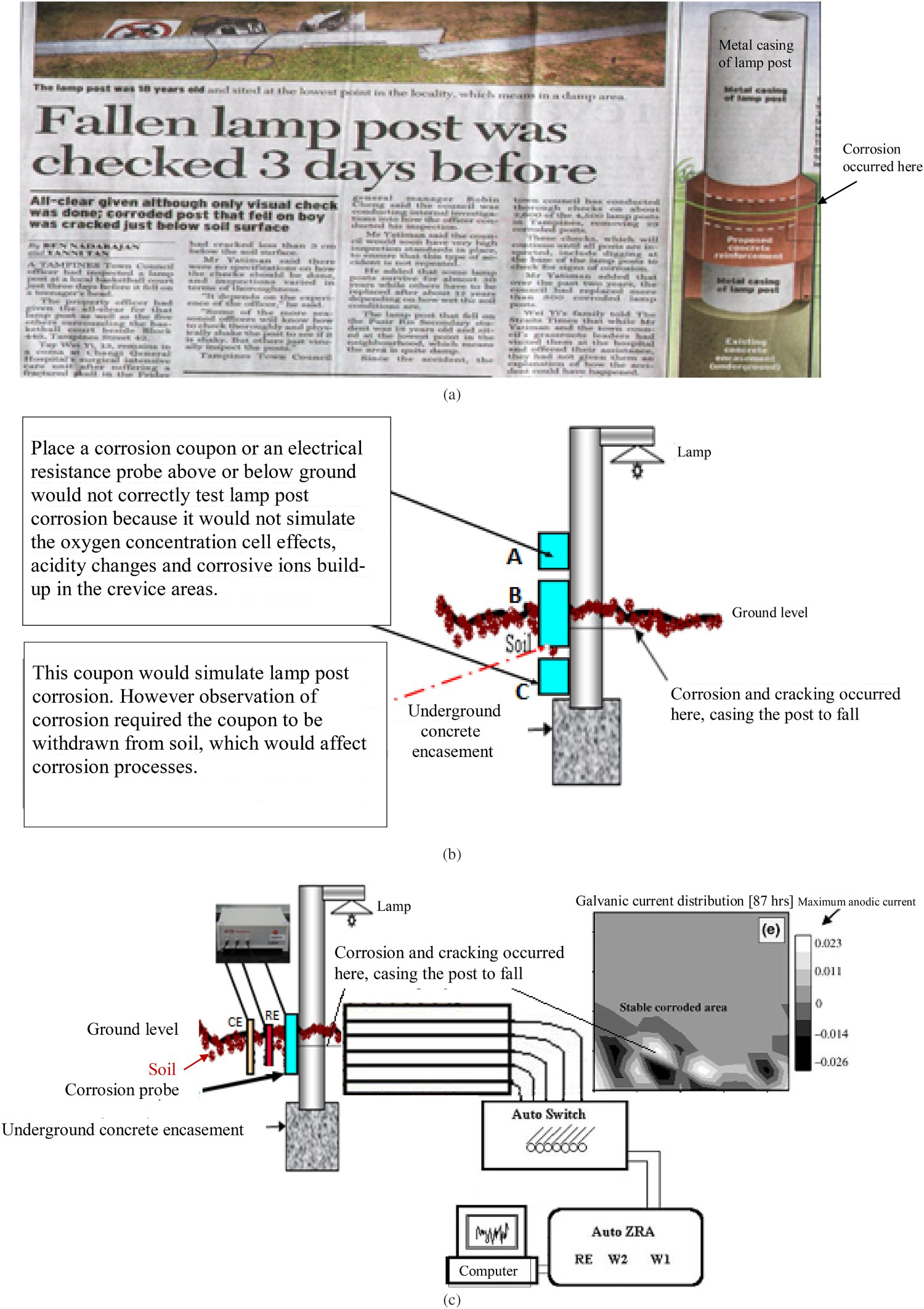
Figure 1(b) illustrates a corrosion monitoring system using metal coupons or ER probes. It is clear that metal coupons or ER probes placed above (coupon A) and below (coupon C) the ground would only indicate the corrosivity of the atmosphere and the soil. They would not provide information about corrosion that caused the lamp post incident, because the critical crevice and galvanic effects and the differential aeration environment that are critical to the corrosion of the lamp post are not simulated on the coupon surface. Although the coupon B that is placed both in and above the ground could be able to correctly simulate the lamp post corrosion, the inspection of the coupon would need to withdraw the coupon from the soil and this could significantly change the corrosion on the coupon.
Figure 1(c) illustrates a corrosion monitoring system using electrochemical probes. Various electrochemical methods, including corrosion potential measurement, potentiodynamic polarisation, LPR, EIS and ENA, could be applied to acquire and analyse corrosion data from electrochemical probes. Corrosion potential can be easily measured by recording the potential difference between a corroding probe and a stable reference electrode. It can be used in conjunction with Pourbaix diagrams as a basic indicator of corrosion thermodynamic status, for instance, to predict active or passive behaviour. Corrosion potential monitoring is often useful in understanding cathodic protection, anodic protection, steel reinforcement corrosion and stray current corrosion problems. Unfortunately, like any thermodynamic quantity, the potential value on its own does not provide information on corrosion rates. The LPR and EIS techniques are employed to measure corrosion rates using the Stern and Geary equation and have been discussed in numerous publications. Although LPR is very useful in determining corrosion kinetics, care should be taken since this technique is accurate only under several fundamental assumptions. In principle, it only applies to a uniform corrosion system with a stable corrosion potential. The corrosion process should involve only one anodic and one cathodic reaction, with both under activation control. The Tafel constants should be known; and there should be only negligible solution resistance. For this reason, application of LPR to practical corrosion systems often provides only semi-quantitative corrosion data with variable accuracy. EIS can be used as an alternative technique for determining polarisation resistance. ENA can be used to determine polarisation resistance, although the prime attraction of ENA is its possibility of early detection and warning of localised corrosion by detecting ‘noise signatures’ [33,34]. The technique involves measurement of the electrochemical noise resistance (Rn) that has been found to be similar (or equivalent) to polarisation resistance [35–39].
Although electrochemical techniques such as LPR, EIS and ENA have been widely used in monitoring and estimating the rates of uniform corrosion in general corrosion systems, they have major limitations in measuring localised corrosion kinetics and distributions. In the case of the probe B, as shown in Figure 1(c), it could only be able to detect a corrosion potential or a corrosion rate that is a mixture of contributions from many local potentials or corrosion rates, none of which we can evaluate independently. Obviously, probes designed based on conventional electrochemical techniques have major technological limitations in measuring localised forms of corrosion, which is responsible for some 70-90% of all corrosion failures, including the type shown in Figure 1. This is especially true in highly resistive conditions, such as in soil, that often cause a huge potential drop commonly referred to as IR drop, causing significant corrosion rate measurement errors [14].
A possible solution to this challenge is the use of a corrosion probe designed based on an electrochemical testing method namely the WBE, an electrochemically integrated multi-electrode array [26–28]. The WBE is an array of mini-electrodes (namely wires) that are insulated from each other by a thin insulating layer. The working surface of the WBE is electrochemically integrated by coupling all the wire terminals in the solid phase and by closely packing all the wires in the solid/electrolyte interface. This electrochemical integration minimises the influence of the insulating layer on electron and ion movements and thus the working surface of a WBE effectively could simulate a conventional one-piece electrode surface in electrochemical activity and behaviour. Indeed the results of comprehensive testing have shown that similar corrosion patterns were produced over WBE and conventional one-piece electrode surfaces when both were exposed to identical corrosion environments and this has been verified theoretically [26–28]. The WBE is useful for studying nonuniform electrode processes because first, each wire in a WBE is an individually addressable electrochemical probe that can be used to measure local corrosion parameters; and second, the surface of each individual wire in an integrated WBE can be assumed to be uniform even if the overall WBE surface is nonuniform. This assumption allows electrochemical theories and techniques developed for uniform corrosion processes to be applied to each wire in an integrated WBE, i.e. traditional corrosion theories and techniques are extended to study localised corrosion and other nonuniform electrode processes. Based on this assumption and the Butler–Volmer equation, new equations describing the electrochemical kinetics of each individual wire have been derived for studying the kinetics of localised corrosion processes [26,40]. Two important characteristics of the WBE method that are particularly valuable for the monitoring of corrosion in complex environmental conditions such as buried structures are, (i) WBE is applicable to high resistance multi-phase environment, which has been demonstrated in a previous study [14,41]; (ii) WBE can map corrosion processes on an instantaneous and continuous basis. Instantaneous corrosion rate maps were determined from corrosion potential and current distribution maps; and the corrosion rate maps were used to calculate accumulated corrosion depth distributions. In order to achieve the highest possible sensitivity of detecting early signs of localised corrosion, the WBE can be used in conjunction with ENA since ENA has the advantage of providing early warning of localised corrosion initiation [14].
As shown in Figure 1(c), a WBE probe is placed both in and above the ground in order to simulate the lamp post corrosion mechanism and processes. The ability of the WBE probe in measuring galvanic current distribution maps has been demonstrated by Aung et al. [30] during the exposure of the WBE to dry, damp and chlorinated sand environments. The probe was able to detect characteristic corrosion at the location below the sand/air interface, similar to the corrosion behaviour occurred on lamp posts, in galvanic current distribution maps of the type shown in Figure 1(c).
Designing a probe for monitoring corrosion under deposits
Figure 2 shows a case of monitoring underdeposit carbon dioxide corrosion and the performance of corrosion inhibitors using corrosion probes. Corrosion inhibitors are used to prevent oil structure failure due to pitting and mesa corrosion under solid deposits such as sands and biofilms. A problem is that the efficiency of corrosion inhibitors is often unknown because it is considered to be nearly impossible to assess by normal corrosion testing techniques [42–47]. For instance, a crude oil pipeline was monitored using a corrosion coupon or an ER probe for corrosion in the bulk fluid, as shown in Figure 2(a). Both the ‘probe A’ and ‘probe C’ recorded very low corrosion rates; however, severe corrosion with significant pitting was found in the bottom of the line where large volumes of sediments existed. There was a significant difference between corrosion monitoring and corrosion behaviour. Underdeposit carbon dioxide corrosion is believed to be controlled by factors including galvanic effects between a large cathode (pipeline surface) and a small anode (surface under deposits), failure of inhibitors to penetrate the deposits and the retention of aggressive species such as bacteria in the deposits. Successful corrosion monitoring would need a probe that could effectively simulate these controlling factors and measure their effects on corrosion rates and patterns.
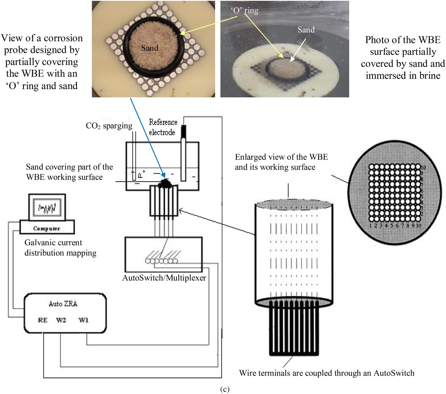
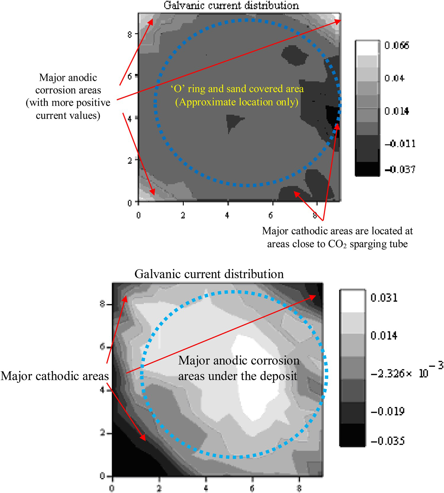
(a) Illustrating conventional metal coupons or probes for monitoring underdeposit corrosion; (b) photo showing a device designed based on a multi-electrode array by Turnbull et al. to study under-deposit corrosion [47]; (c) schematic diagrams showing a corrosion probe designed using the WBE to simulate and monitor underdeposit corrosion and its inhibition; (d) a typical galvanic current distribution (in mA cm–2) map measured over a WBE exposed to a brine-CO2 corrosion environment for 18 h without inhibitor present; (e) showing underdeposit corrosion 97 min after 30 ppm inhibitor imidazoline was added into the system [47]. Continued. Continued.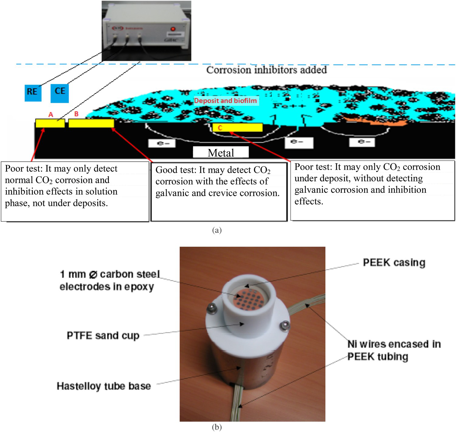
Several different test devices/probes were designed in attempts to simulate these complex environmental factors. For instance, de Reus et al. [44] used two sets of three-electrode arrays with one set covered with sand and another directly exposed to brine solution. Such device was designed to allow simultaneous electrochemical monitoring and measurements at both uncovered and covered areas for direct electrochemical comparison. Although this method should be able to detect the effects of the possible formation of a localised differential concentration cell, the possible failure of inhibitors to penetrate the deposits and the possible retention of aggressive species in the deposits on corrosion rates, it is unable to simulate galvanic corrosion activities associated with underdeposit corrosion mechanisms. Obviously failure to measure galvanic currents flowing between covered and uncovered areas would lead to underestimation of underdeposit corrosion. Pedersen et al. [45] designed a corrosion monitoring device that used three specimens with two specimens covered with sand and one directly exposed to brine solution. One of the covered specimens was coupled to the uncovered specimen. Corrosion inhibitors were assessed by detecting galvanic currents flowing between the sand-covered and uncovered specimen. This test allowed the simulation of galvanic activities between a large cathode and a small anode and the measurement of galvanic currents. Using this test device, it was found that the sand-covered specimen was anodically polarised and was under localised corrosion attack. However, this device may not work in highly resistive media such as a multi-phase fluid where a high electrolyte resistance would prevent galvanic current flowing between the far-spaced sand-covered and non-covered specimen. Another issue is that the device would not effectively simulate localised chemical changes over a partially covered metal surface due to local corrosion reactions and the retention of aggressive species in the deposits. The artificial pit electrode method [46] uses a pit electrode that is coupled through a zero resistance ammeter to a large piece of steel. In this device, galvanic current is believed to relate to the rate of pit propagation and its change before and after inhibitor addition is used as an indicator for assessing inhibitor performance. Although this method should be able to detect and monitor galvanic currents flowing between localised anodes and cathodes over a partially cover metal surface, it has similar limitations to the method by Pedersen et al. [45] in detecting galvanic current in highly resistive media and in simulating ion diffusion and chemical changes over a partially covered metal surface. Another critical issue is that this method does not measure direct underdeposit corrosion attack. For instance in the case of corrosion under a bacteria containing deposit, bacteria activities can generate oxidising substances such as acids underneath the deposits, leading to direct acid corrosion. Under this situation, no measurable galvanic corrosion could be detected by a zero resistance ammeter that couples the electrode to a piece of external steel and thus the artificial pit electrode method would be unable to evaluate this type of underdeposit corrosion or its inhibitors.
Based on a multi-electrode array, Turnbull et al. [47] designed a device to monitor and study underdeposit corrosion. They used an electrode array that consisted of 24 electrodes (each of 1 mm in diameter). The schematic representation of the device is given in Figure 2(b). However, when the sand cup is filled with sand, all the electrodes in the array would behave similar to the ‘coupon C’ in Figure 2(a). Therefore this probe would not able to simulate and monitor the galvanic effects due to a large cathode to anode surface area ratio, as experienced by underdeposit corrosion of pipelines. On the other hand, the large gaps between each individual electrode in the electrode array would prevent the simulation of the galvanic effects and chemistry interaction among neighbouring locations on a single piece metal surface.
Tan et al. designed a test method based on the WBE to avoid difficulties in the testing and monitoring underdeposit corrosion and its inhibitors [42]. Figure 2(c) shows a schematic diagram of a corrosion probe that was constructed by partially covering the WBE working surface with a rubber ‘O’ shaped ring filled with sand. This partially covered WBE probe surface was exposed to a custom-made electrochemical testing cell to simulate a localised underdeposit corrosion environment. The capability of this corrosion probe was demonstrated by mapping corrosion potentials and galvanic currents across the multi-electrode array with the effects of several inhibitors. Very different corrosion behaviour was observed from a partially covered WBE surface exposed to a CO2-saturated brine environment with and without the presence of corrosion inhibitor imidazoline. Without inhibitor, as shown in Figure 2(d), positive galvanic currents concentrated mainly on areas uncover by ‘O’ ring and sand, while cathodic currents distributed mainly over areas closer to CO2 sparging tube. This result suggests that underdeposit corrosion was not occurring in a CO2-saturated pure brine solution under ambient temperature because the area under the sand behaved as cathode. When inhibitor imidazoline was added into the brine solution, as shown in Figure 2(e), corrosion anodes and cathodes quickly switched locations with corrosion anodes shifted to areas cover by ‘O’ ring and sand, while cathodes located mainly over the four corners where no sand was present. This case illustrates the complexity of underdeposit corrosion and the effects of inhibitors, and the benefits of corrosion monitoring.
New progresses in monitoring pipeline corrosion and coating degradation
Recently extensive research has been carried out to enable the monitoring of localised corrosion attacks on steel pipelines exposed to complex environmental conditions such as in highly resistive and inhomogeneous soil media, as well as under the effect of dynamically changing environmental conditions. It is a highly challenging task to design corrosion probes, especially localised corrosion probes, which are able to effectively simulate corrosion behaviour in actual pipeline service environments and reliably evaluate the effects of various factors on corrosion processes, rates and mechanisms. A successful corrosion probe should be able to detect the effects of major corrosion controlling factors on corrosion mechanism, process and rates. The identification and understanding of major environmental factors that may control the thermodynamics, kinetics and mechanism of a corrosion process is usually the first step to successful corrosion probe design. The identification of corrosion controlling factors requires good knowledge of the nature and mechanism of a corrosion process. For instance, aeration is a critical corrosion controlling factor that could affect corrosion in complex environmental conditions such as buried pipelines. In the case of active mild steel corrosion in soil, the corrosion rate determining factor is often the diffusion of oxygen to the metal surface. When cathodic protection is applied on the steel, the corrosion control factor could be changed to high pH-induced passivity of the steel surface.
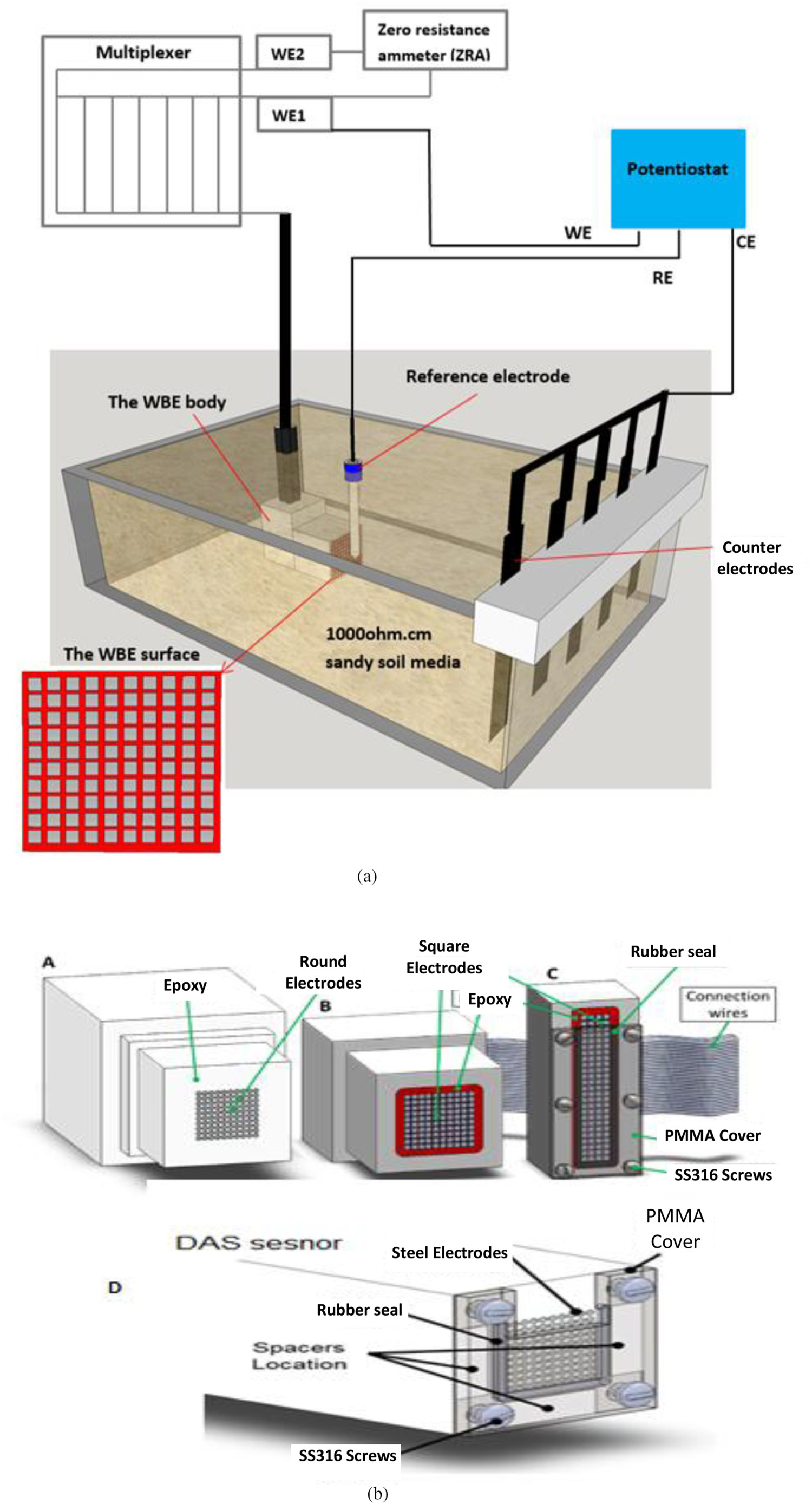
One recent progress in pipeline corrosion monitoring is the design of corrosion and coating degradation probes by innovatively applying the electrode array. The capability of the electrode array-based corrosion probes in detecting the initiation and propagation of localised corrosion and coating failure can be illustrated by several application cases [48–51]. Figure 3 illustrates a typical experimental configuration using an electrochemically integrated multi-electrode array-based probe to facilitate the in situ monitoring and visualisation of electrochemical processes occurring on buried steel surfaces under CP and anodic transient conditions [48]. The WBE probe used in this work consists of 100 closely packed but isolated square-shaped carbon steel electrodes (e.g. 2.44 mm x 2.44 mm) embedded in epoxy resin. Similar electrochemical cells and experimental set-up were used in various experiments for studying various inter-related processes such as cathodic shielding and localised corrosion [49,50], coating damage and disbondment [51]. More details on the experimental and data analysis methods can be found elsewhere [48–51].
New probe for monitoring localised corrosion under disbonded coatings [49,50]
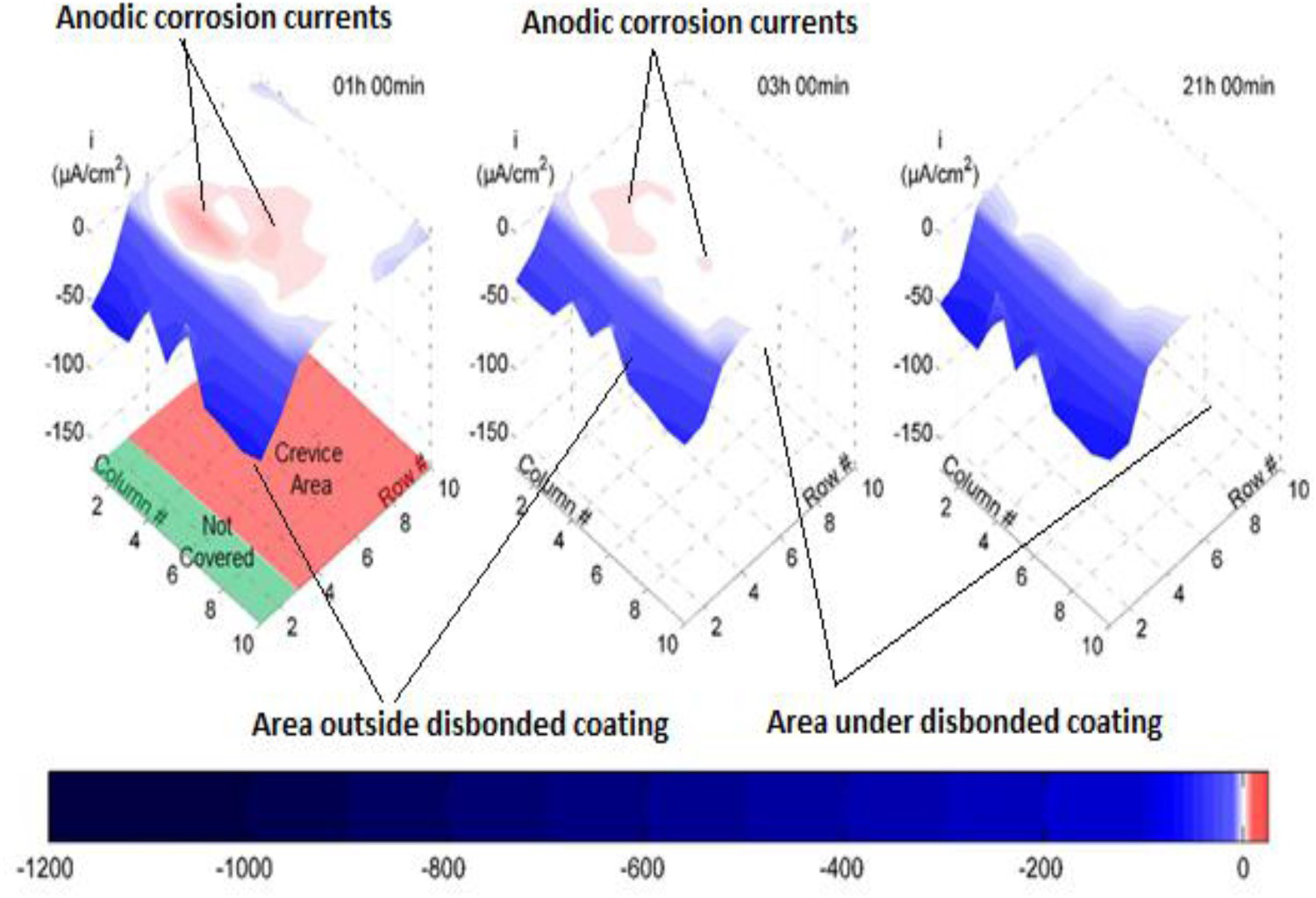
Figure 4 presents the current density maps developed from the probe's measurements at a CP potential of −850 mVCSE. Cathodic current densities are displayed in negative values while anodes in positives. The section of the electrode covered by the crevice is indicated at the base of the first current density map. The probe was able to provide generate a map every 20 min during the immersion tests, although only three maps were selected to illustrate the general trends observed in the experiment. In general, large cathodic current densities were found at the uncovered area, indicating CP protection, while current densities along the crevice were extremely low. Although the current densities registered at the uncovered area remained constant throughout the test, significant changes were observed within the crevice area. In this area, anodic current densities were found at the beginning of the test that rapidly decrease in magnitude. After this initial period, stable current densities minor to 1 µA cm–2 were recorded throughout the remaining of the test. More detailed data acquisition, visualisation and interpretation for monitoring corrosion under disbonded coatings can be found in references [49,50].
Probing dynamic corrosion under anodic stray currents [48]
Significant effort has been made to systematically categorise and quantify the level and nature of damage of pipeline as a result of CP excursions, a form of stray currents, there are still major difficulties in drawing decisive conclusions because of the complexity of the electrochemical corrosion processes occurring at the complicated soil/buried steel interface. A major difficulty is the lack of reliable and reproducible experimental methodologies that are able to systematically categorise and quantify the level and nature of damage as a result of various modes of CP excursions. Currently, potential recording is the most commonly used method for inspecting stray current activities in the pipeline industry; however, potential recording does not provide sufficient information about corrosion rates and patterns. Weight-loss coupons have been used to determine corrosion rates of steel buried in soil; however; weight-loss coupons are unable to provide in situ corrosion rate data required for quantifying the effects of relatively short duration CP potential excursions. Recently the WBE method has been applied for the first time as a new probe for detecting localised corrosion initiation under various dynamic anodic transient influences. Experiments have been carried out for measuring the effect of an anodic transient on the corrosion of a steel WBE probe in a soil corrosion cell [48]. Typical series of results are shown in Figure 5. A common phenomenon that was observed from these tests is that shortly after an anodic transient was applied to a CP protected steel surface, anodic current and corrosion activity dropped dramatically from an initial anodic current peak value. This has been explained by the passivity of steel under CP induced high pH conditions. Another phenomenon observed by inspecting the occurrence of local anodic currents in WBE maps was that localised corrosion initiation occurred after a critical duration. This critical duration could be explained by the breakdown of passivity under the effects of anodic transient-induced pH and surface chemistry changes. This work suggests that the WBE probe could be used as an effective tool for monitoring localised corrosion initiation under the effect of complex factors, as well as for the in situ monitoring of stray current corrosion of buried steel structures. More detailed data acquisition, visualisation and interpretation for monitoring stray current corrosion under the effect of anodic transients can be found in reference [48] (Figure 5).
Monitoring of currents and WBE maps over a steel WBE buried in a soil cell under three different CP and anodic transient conditions [48]. Typical maps of impedance amplitude (│Z│ at 300 mHz) and direct currents measured over a coated probe after various periods of exposure and under different CP potentials [51].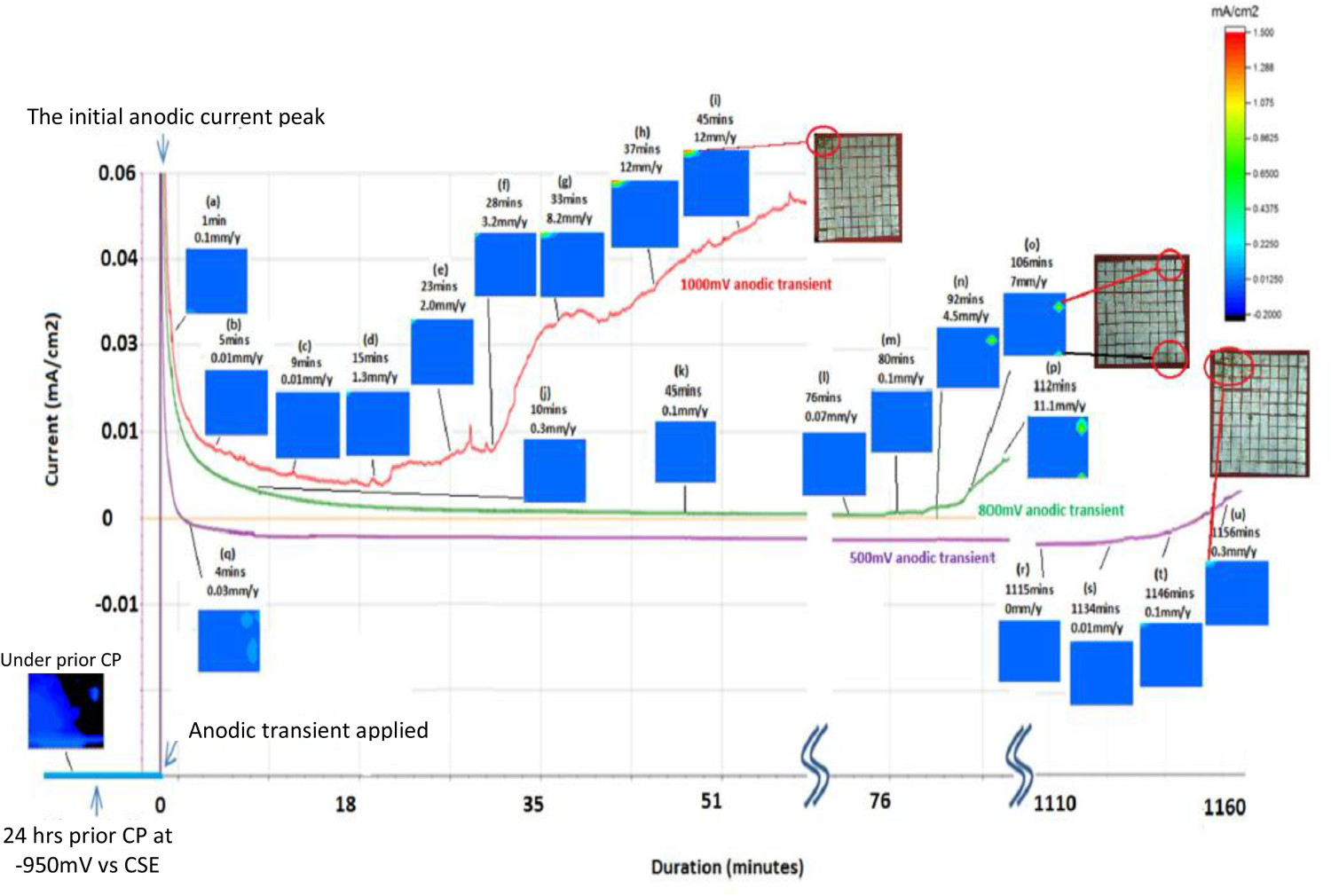
New probe for monitoring of coating cathodic disbondment under overprotection [51,52]
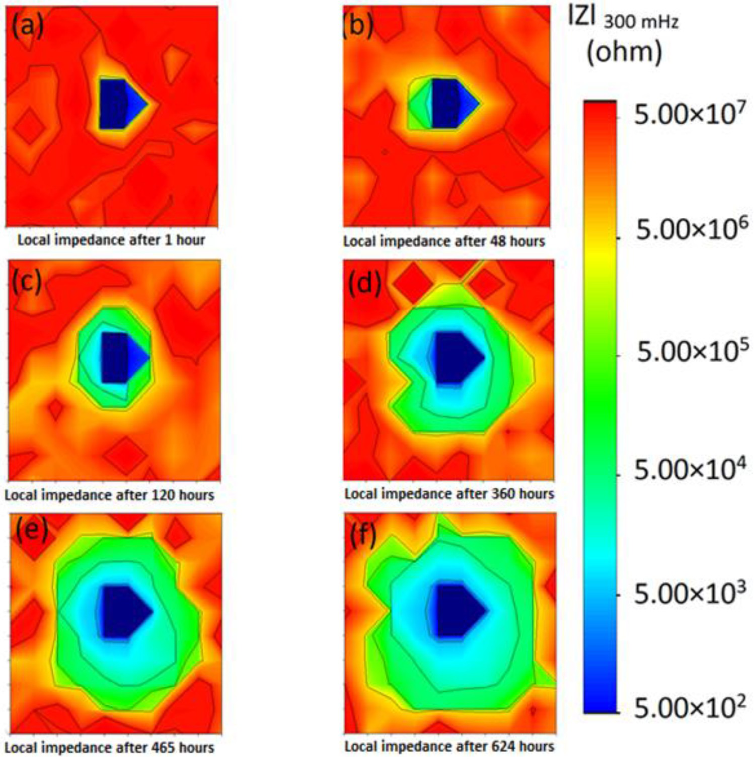
Cathodic disbondment is a major form of electrochemically induced coating failure that frequently takes place at the metal/coating interface on cathodically protected steel infrastructure such as pipelines. Extensive research over the past decades has developed a good understanding of the phenomenon; however, currently there is no technique that can be used to perform in situ monitoring of its occurrence in the field. Traditional methods of evaluating cathodic disbondment of pipeline coatings are based on ex situ visual inspection of excavated pipes. Recently a new probe has been developed by modifying the electrode array [51]. Figure 6shows typical data in the form of maps of local impedance amplitude measured after different periods of exposure of the probe to the test solution under CP potential of −1.40 V Ag/AgCl or −0.95 V Ag/AgCl. It is clearly shown in maps (a)–(f) that, under a CP potential of −1.40 V Ag/AgCl, the impedance of electrodes surrounding the defect area continuously decreased (to less than 105 ohm) over the 624 h exposure period. These low impedance areas expanded with the increasing exposure time, while electrodes located far away from the defect area maintained a high impedance of larger than 107 ohm after 624 h. These maps clearly indicate coating disbondment due to permeation of the test solution along the disbonded coating/metal interface gap rather than absorption of the solution by the coating. After 624 h, as shown in Figure 6(f), the majority of electrodes on the probe were disbonded. More detailed data acquisition, visualisation and interpretation for monitoring stray current corrosion under the effect of anodic transients can be found in reference [51,52].
Remaining issues in corrosion monitoring probes and future perspectives
Although new approaches to corrosion probe design, such as those described above, helps addressing the simulation and monitoring of some critical forms of localised corrosion, care still needs to be taken. There are still limitations in corrosion probes including those designed based on the WBE method. It should also be noted that the electrode array based probes design described in this paper is only examples showing new possibilities of corrosion probe design, without excluding any other probe design possibilities and innovatives. Several critical remaining issues will need to be made in order to significantly enhance the reliability and applicability of corrosion probes as a structural health monitoring tool.
New development needs in designing probes for complex localised corrosion mechanisms
Since successful corrosion probe application in an IHM system requires the probe surface to simulate not only the corrosion environment, but also the critical corrosion mechanisms occurring on the infrastructure, significant attention should be given to addressing challenges in understanding localised corrosion mechanisms and in correctly monitoring them. A challenge comes from situations that several corrosion mechanisms occur instantaneously. In this case, the first step of cultivating a corrosion probe for an IHM system for a particular infrastructure should be the identification of most important localised corrosion mechanisms that can cause major structural integrity, durability and reliability concerns, followed by the selection and design of probes or sensors that are able to collect data/parameters related to these concerns. An approach that could be used to simplify corrosion probe design is to design probes that simulate and detect the ‘worst-case scenario’ corrosion mechanism. Currently, understanding of these aspects has been insufficient and more advancements are needed in order to develop appropriate corrosion probes for future industry corrosion monitoring.
Development of probe application rules
A corrosion probe needs to be applied properly in order to correctly simulate and measure corrosion issues of interest. For instance, as illustrated in Figures 1 and 2, corrosion coupons can provide invalid corrosion data if not used correctly. It can become a more reliable corrosion testing, monitoring and predictive tool if it is applied carefully. In order to fully realise the advantage of corrosion probes for providing site-specific and in situ warning of unexpected structure failures, corrosion probes should be placed at strategic and ‘worst-case scenario’ high-risk locations of a infrastructure. For a buried pipeline, for instance, typical high-risk structure sites would be those with high stray current activities, low soil resistivity, high underground water level, high concentration of corrosive species, and those highly corrosion rate areas identified by pigging, field survey and historical excavations. Other examples of high-risk pipeline sections include non-piggable pipeline sections, areas between cathodic protection units, pipeline water crossings, pipeline shoreline crossings, horizontal directional drilling and pipelines in tunnels. These pipeline sections could present the ‘worst-case scenario’ conditions that are crucial to the safety and reliability of an energy pipeline. Pipeline sections of high economic and social significances may also be identified as monitoring sites. Probes embedded at these strategic sites can be used to collect real-time and site-specific data that would contain critical ‘predictor features’ and parameters needed for modelling and predicting localised corrosion, coating disbondment and degradation. Currently understanding of these aspects has been limited and more advancements are needed in order to develop rules and guidelines for future industry corrosion monitoring.
Development of measurement techniques
Another challenge is to develop or select suitable measurement techniques that are able to effectively and accurately detect data from corrosion probes. It is well known that these conventional electrochemical methods can only be used for estimating general corrosion behaviour because, in principle, they are based on the most fundamental relationship in electrochemical kinetics, i.e Butler–Volmer equation, which only describes the kinetics of uniform corrosion mechanism and thus does not apply to localised corrosion [26–28]. Over the recent decades, new methods such as galvanic current mapping using multi-electrode arrays and ENA have been developed to detect ‘predictor features’ signifying the occurrence of localised corrosion.
ENA is a technique proposed and utilised for detecting localised corrosion and for measuring corrosion rates [33–39] based on the analysis and correlation of electrode potential fluctuations and corrosion processes. The prime attraction of ENA is probably its possibility of early detection of localised corrosion by detecting ‘noise signatures’. The noise signatures were proposed to detect localised corrosion by recognising characteristic noise patterns (often referred to as noise signatures) in the time domain [33] or in the frequency domain [34]. In the time domain, Hladky and Dawson discovered that electrodes undergoing either pitting or crevice corrosion would generate quite distinct noise signatures in potential fluctuations [33]. They found that potential noise associated with pitting corrosion initiation is characterised by a series of sharp decreases of the electrode potential followed by exponential recoveries. They concluded that pitting or crevice corrosion attack can be detected within seconds of their initiation. Based on these findings, they advocated the use of characteristic noise patterns as indicators of localised corrosion [33,34,39] and suggested the possibility of a non-perturbative electrochemical corrosion monitoring technique capable of detecting localised corrosion. Having obtained potential and current noise time records, many methods can be used to analyse the data which are summarised in a comprehensive review by Cottis [39]. Although localised corrosion sensing by means of ENA has had progress over the past decades, there are still several unanswered issues that limit its practical applications. Electrochemical noise should be useful for identifying periods when the corrosion processes become unstable, and to recognise when the probability of localised corrosion is high, for instance, as a function of corrosion inhibitor addition. This is an example of need for further development of corrosion measurement techniques.
Development of data analytics systems and IT platforms
Although corrosion probes can provide useful in situ data from selected locations of an asset, there is a need to integrate data from limited monitoring sites into the whole database by suitable models in order to provide fuller coverage of a huge structure (e.g. a 1000 km underground pipeline). An information platform would enable the integration of various data inputs and allow industry to cost effectively gather information on the in-service integrity of assets/infrastructure, gain high levels of confidence in the condition of the asset, timely maintenance, safety and continuous availability/operation of the asset. A solution is an information platform for infrastructure health monitoring, failure prediction and life extension. The idea is to develop a web-based information platform that can linkup multiple industries and multi-disciplinary areas of research. This platform ‘visualises’ what's happening underground by taking and linking up different sources of corrosion and material degradation data available. It will include corrosion probes as an in situ corrosion monitoring information source. This platform will allow continued data input from various information sources such as remote corrosion monitoring, industry inspection; and the analysis and application of data for various purposes such as structural failure prediction and life extension. For instance, risk assessment models can be employed to prioritise the assets for maintenance and renewal.
It is expected that health monitoring and data analytics will become much more common with further development to enhance the reliability of monitoring probes and prediction modelling. These will enable ‘predictive maintenance’ and lead to the gradual adoption of it in the infrastructure management and maintenance industry, for early detection and diagnosis of corrosion, for providing industrial system health alarms, for forecasting maintenance requirements.
Concluding remarks
The principles, issues, advantages and disadvantages of corrosion probe technologies for corrosion monitoring have been briefly reviewed, with a particular focus on their application in the oil and gas pipeline environmental conditions. It is shown that currently the prime challenge in corrosion monitoring is difficulties in simulating localised corrosion mechanisms on corrosion probe surfaces, especially when corrosion mechanisms are complex and change with the extension of corrosion. Further developments are needed to enhance the reliability of corrosion monitoring by improving the design and application of corrosion probes. A major reason that could lead to reporting of false corrosion rates and patterns have been identified to be the inappropriate design and use of corrosion probes that overlook various corrosion mechanisms and possible changes in corrosion mechanisms with the extension of corrosion processes. As an example, electrochemically integrated multi-electrode arrays have been shown to possess potential as a basis for designing various corrosion probe suitable for monitoring complex forms of localised corrosion. It is expected that corrosion monitoring probes will become an important and widely applicable tool in IHM systems to acquire, visualise and interpret industrial system ‘health’ information, enabling early detection, warning, diagnosis and prediction of infrastructural corrosion and failure.
Footnotes
Disclosure statement
No potential conflict of interest was reported by the author.