
Abstract
Air-assisted steam injection is used as a secondary or tertiary oil recovery technology. During closing, downhole tubular goods are subject to corrosion in a mixed oxygen–steam–hot solution environment. This study investigates the influence of air injection pressure, temperature and Cl− ion concentration in the injection water on the corrosion of P110 steel. Results show that high air injection pressure for increasing oil recovery ratio leads to the highly aggressive corrosion. The trend of corrosion rate and temperature in air-saturated injection water is a reversed ‘V’ curve. However, the high Cl− concentration, which promotes the formation of large holes in the magnetite scale, greatly reduces corrosion. A suitable injection press that balances the oil recovery ratio and corrosion rate of oil tube, avoiding 170°C suitable for the highest corrosion rate, and periodic removing corrosion scales are necessary to inhibit further deterioration of downhole tubular goods.
Introduction
In air-assisted steam injection for a secondary or tertiary oil recovery technique, steam is injected into well promptly after air injection. Oil tubes are subject to corrosion from air-saturated hot steam and hot solution, especially the Cl− ion from injection water. Uniform corrosion, serious local corrosion and even cracks can occur on the surface of oil tubes, and the service life of oil tubes can be shortened [1–3].
At present, investigations on Fe in an O2–H2O corrosion system are focused on O2 penetration at the inlet of pipelines and O2 impurities in the supercritical CO2 environment [4 -16]. However, the studies refer to aqueous systems with low levels (ppm) of dissolved oxygen and temperatures below 90°C. Owing to the differences in the solubility of gas, activity of ions and chemical composition of corrosion scales, the corrosion rules and mechanisms based on room temperature and pressure are not applied to the corrosion system in environments with high temperature and pressure.
Surveys on Cl− ion in an Fe–H2O corrosion system concentrate on the Fe–CO2–H2O corrosion system. High-concentration salt decreases the CO2 corrosion rate significantly [17, 18]. However, Foley et al. found that the corrosion rate rises slightly at low chloride concentration but decreases at high chloride concentration [19,20]. In their studies, the highest corrosion rate was obtained at 25 g L−1 Cl− concentration at 20 bar CO2 pressure [20].
To date, work that investigates the corrosion rules and mechanism of Fe in an O2–Cl−–H2O system, especially at high temperature and pressure, is lacking. Previous research findings cannot offer direct guidance on ways to protect oil tubes from corrosion.
The aim of this study is to inhibit downhole O2 corrosion through the selection of suitable injection process parameters. P110 steel, a grade commonly used for oil well casings, was used to investigate the effect of injection air pressure, temperature and Cl− concentration in injection water on the corrosion behaviour of oil tube steel. The weight loss method was used to calculate the corrosion rate of specimens in high temperature and high-pressure environments. Analytical techniques, including scanning electron microscopy (SEM), energy-dispersive X-ray spectroscopy (EDS) and X-ray diffractometry (XRD), were used to study the corrosion scales.
Experimental
Materials and specimens
Chemical composition of P110 (wt-%).

Preparation of corrosion solution
Chemical composition of softened water of oil (mol L−1).
Immersion experiments
Experimental parameters in this work.
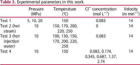
In the immersion experiment, the specimens were fixed on the holder, and 800 mL of simulated injection water was injected into the autoclaves. Artificial air was injected into autoclaves via the gas inlet. Pressure in the autoclaves was adjusted by an outlet valve. The corrosion time was 12 h.
Mass loss measurements
All specimens were removed from the autoclaves after corrosion testing. A boiling cleaning solution (20 wt-% NaOH solution + 20 wt-% zinc powder) was used to remove the corrosion product. The specimens were rinsed with distilled water, cleaned in anhydrous ethanol and dried under an N2 gas stream.
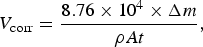
The uniform corrosion rate (mm per year) was calculated from the specific weight loss using the following equation:
Results
Effect of air injection pressure
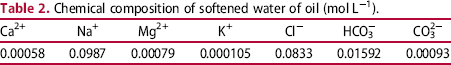
Figure 1 presents the corrosion rate of the P110 steel specimen under different air injection pressures. The corrosion rate of the specimen rapidly increased from 32.07 to 60.25 mm per year when air pressure in the autoclaves increased from 5 to 10 MPa. When air injection pressure was increased further, the corrosion rate slowly reached 72.83 mm per year at 20 MPa. In any event, increasing air injection pressure was unfavourable for the service life of the oil tubes.
Corrosion rate of the P110 steel in 5, 10 and 20 MPa air pressure system.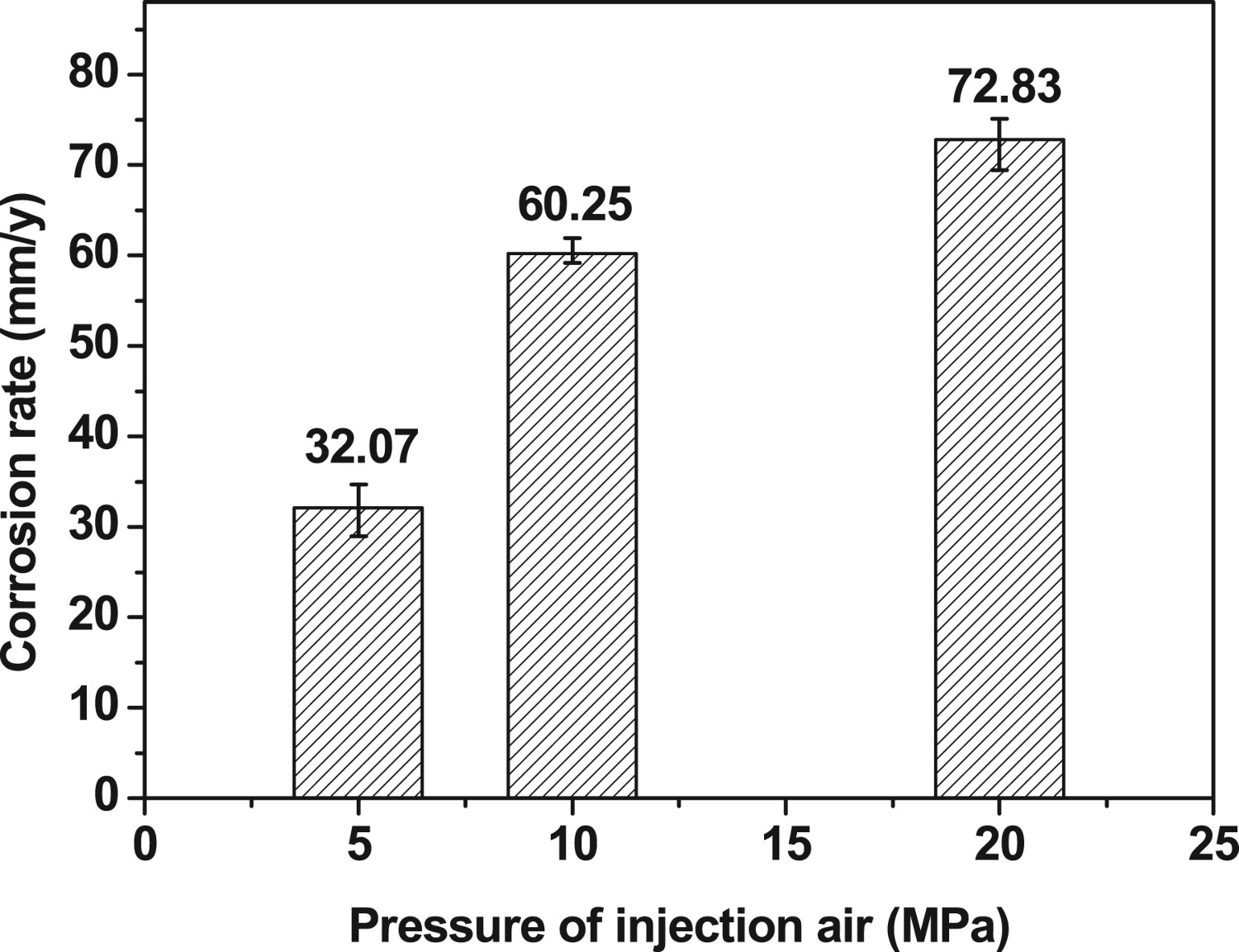
Figure 2 shows the macroscopic morphologies of corrosion scales formed under different air pressure values. Loose corrosion products were deposited on the surface of the specimen and easily stripped. Different from a CO2 environment, increasing air injection pressure had little effect on the adhesion of corrosion scales. The non-compact structure of corrosion scales was attributed to the concentration polarisation from corrosion scales, leading to the high corrosion rate for oil tubes in the downhole environment.
Morphology of corrosion scales formed in 5 MPa (a), 10 MPa (b) and 20 MPa air pressure system (c), respectively.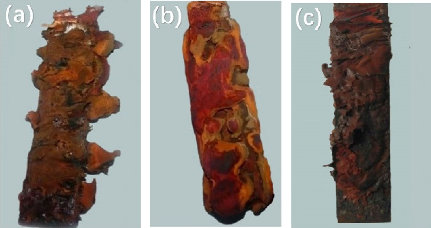
Effect of air injection temperature
In air-assisted steam injection, the upper and lower oil tubes are subjected to the corrosion from air-saturated hot steam and air-saturated hot solution, respectively.
Figure 3 shows the macroscopic morphologies in an air-saturated hot steam environment. Corrosion uniformly developed on the surface of the specimen at 170°C and was more serious than that at 150°C and 200°C, both of which occurred on the local surface of the specimen. When the temperature exceeded 200°C, as shown in Figure 3(c–e), the specimen entered the state of bluing. A thin and compact film formed on the surface of specimen and protected the specimen from further corrosion.
Corrosion morphology of P110 specimen formed in 150°C (a), 170°C (b), 200°C (c), 220°C (d), and 250°C air-saturated hot steam system (e), respectively.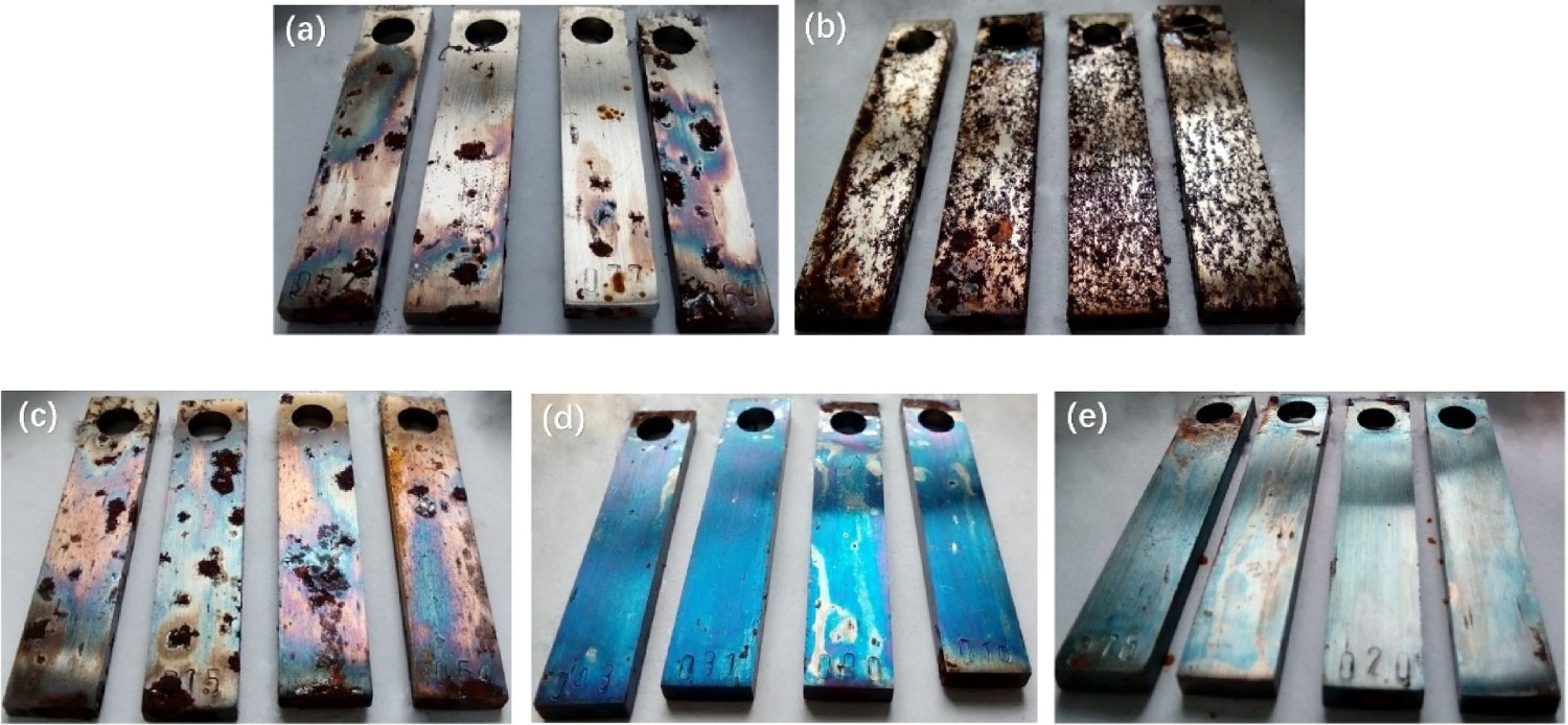
Figure 4 presents the corrosion rates of the P110 specimen in air-saturated injection water under 10 MPa pressure. The corrosion rate of the specimen increased with increasing temperature at low temperature but decreased at high temperature. The highest corrosion rate was 69.67 mm per year and occurred at 170°C. The relationship between the corrosion rate of P110 steel and temperature was a reversed ‘V’ curve. Compared with the finding in Figure 3, the corrosion of the oil tube in hot air-saturated steam can be disregarded in air-assisted steam injection.
Corrosion rate of P110 steel in air-saturated injection water system.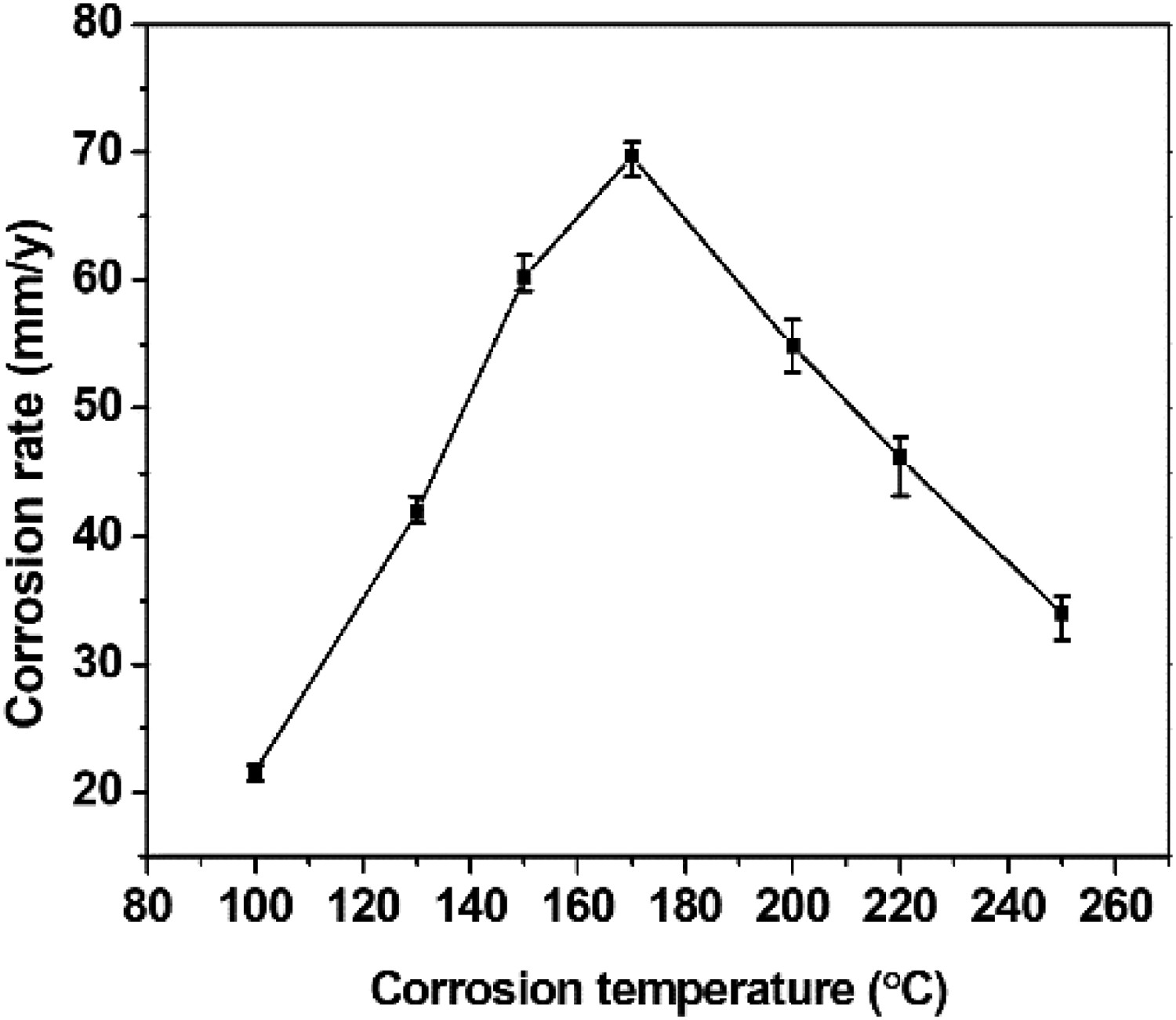
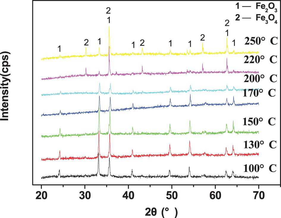
Figure 5 shows the microscopic morphology of corrosion scales formed in four types of temperature. The compactness of corrosion scales slightly increased with increasing temperature. However, the shape of the corrosion products changed substantially. At low temperatures, the surface of the specimen was covered with granular-shaped corrosion products (Figure 5a and b), while at high temperature, the surface was covered with needle-shaped and flower-shaped corrosion products (Figure 5c and d). The XRD spectrum for corrosion scale (Figure 6) indicated that the Fe2O3 phase was the single product under 200°C, and the Fe2O3 and Fe3O4 phases constituted the corrosion scale at 220°C and 250°C, respectively. The morphology shown in Figure 5 suggests that the Fe3O4 phase formed at high temperatures facilitated the compactness of corrosion scales.
SEM images of corrosion scales formed in 130°C (a), 170°C (b), 220°C (c) and 250°C air-saturated injection water (d), respectively. XRD spectrum of corrosion scales formed in air-saturated injection water.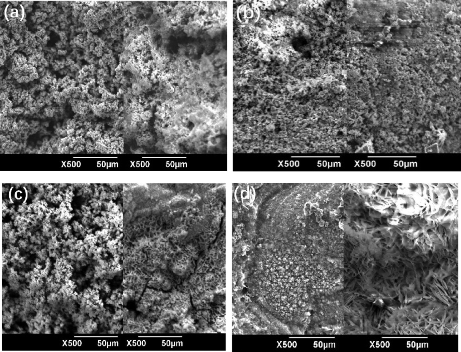
Effect of Cl− concentration in injection water
Figure 7 presents the corrosion rate of the P110 specimen in air-saturated injection water containing Cl− with different concentrations. The highest corrosion rate was 60.25 mm per year in a solution that contained 0.083 mol L−1 Cl− ion, whereas the lowest corrosion rate was 28.98 mm per year in a solution that contained 1.37 mol L−1 Cl− ion. Although some minor fluctuations were observed, the corrosion rate was distinctly diminished with increase of Cl− concentration. The presence of Cl− ions relieved the corrosion of steel in air-saturated injection water. Figure 8 shows the XRD spectrum on a corrosion product on the surface of the specimen. The Fe2O3 phase was the only corrosion product, and chloride was not detected.
Corrosion rate of P110 steel in injection water containing different Cl− concentrations. XRD spectrum of corrosion scales formed in injection water containing different Cl− concentrations.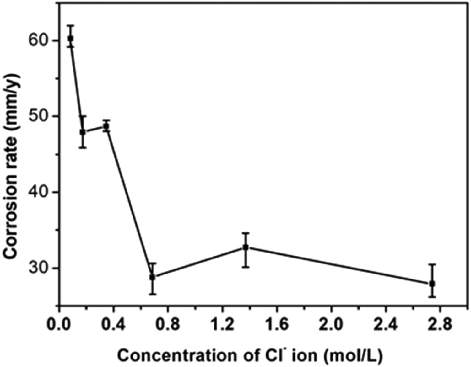
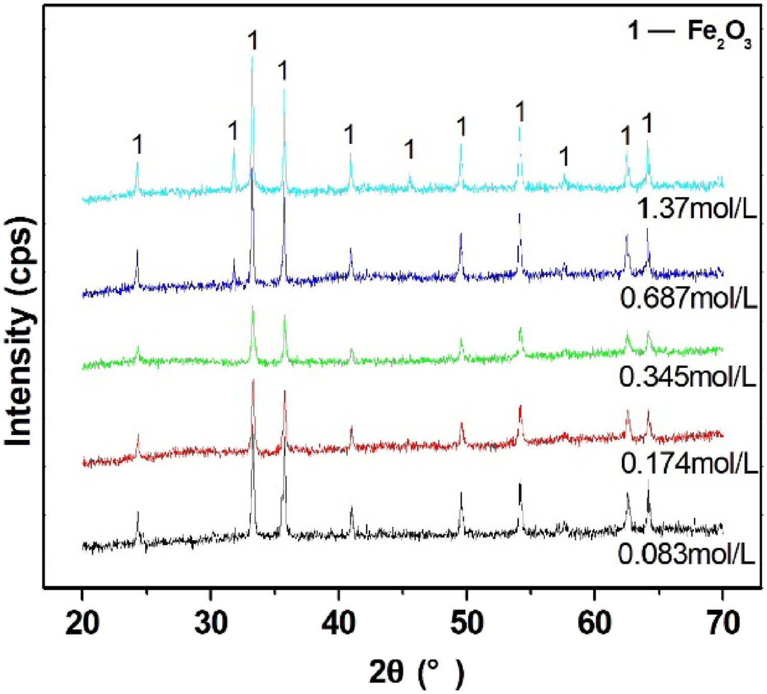
Figure 9 shows the corrosion morphology of the P110 specimen in air-saturated injection water that contained different Cl− concentrations. Many of corrosion pits were observed on the surface of the specimens in three types of Cl− ion concentration environment. As shown in Figure 9a, a large corrosion pit was developed by the interaction of small pits. Large pits reached 800-1000 µm in size, while small pits were approximately 100 µm in size. Small and shallow pits covered the surface of the specimens in the environments that contained 0.174 and 0.345 mol L−1 Cl− ion. The corrosion of the P110 specimen in solution with low Cl− concentration was more severe than that in solution with high Cl− concentration, indicating that the corrosion pits were triggered by O2 or OH− ion, not Cl− ion.
SEM images of corrosion morphology in injection water contained 0.083 (a), 0.174 (b) and 0.345 mol L−1 Cl− ion (c), respectively.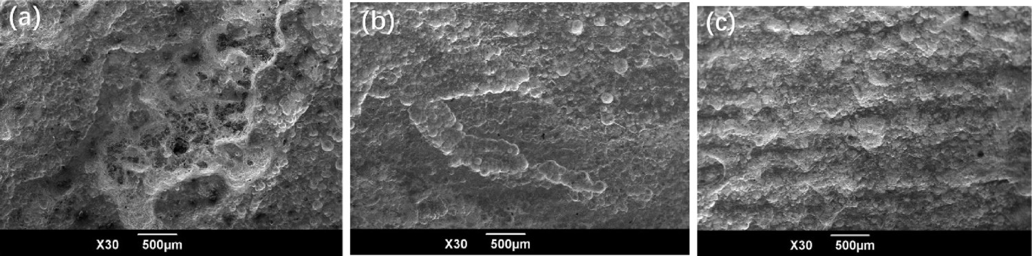
Discussion
When steel was immersed in the O2-saturated solution, the Fe atom in steel lost two electrons and entered the solution as Fe2+ ion. The dissolved O2 turned into OH− ion through reduction reaction at the cathodic area. The corrosion products, such as Fe(OH)2, were deposited on the surface of the sample. The reaction is shown in Equations (2)–(4).


Generally, the metal dissolution rate is decided by electrochemical reaction rate on the interface of metal/solution and the properties of corrosion scales. For cathodic O2 reaction, the concentration of dissolved O2 at interface zone is the key factor on metal dissolution rate.
The electrochemical reaction rate on the interface of metal/solution increased for high ionic migration rate as temperature rose. Whereas the concentration of dissolved O2 in solution decreased with increasing temperature. At low temperature (100°C–170°C), O2 diffusion was the control process of electrochemical cell. Anodic reaction rate increased with increasing temperature. At high temperatures (170°C–250°C), the low concentration of dissolved O2 in bulk solution leaded to the low reaction rate though ion migration rate was high.
Furthermore, the newly formed Fe(OH)2 was oxidised rapidly into Fe(OH)3 owing to the strong oxidation of O2(aq) at the interface zone.


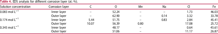
For an Fe–O2–Cl−–H2O corrosive system, corrosive ions include Cl− and OH− ions. Figure 10 shows the SEM images of corrosion scales formed in injection water containing corrosive Cl− ion and OH− ion. The Cl− concentration affected the compactness of corrosion scales. As shown in Figure 10(a–i), no hole was observed in the outer layer, while the number and size of holes in the inner layer increased with increasing Cl− concentration. In the solution with 0.687 and 1.37 mol L−1 Cl− ion, large holes were visible in the outer layer, as shown in Figure 10(j and k). The microstructure of corrosion products in the inner layer was also changed from particle shape to needle shaped (Figure 10l).
SEM images of corrosion scales in injection water contained 0.083 mol L−1 Cl− ion (a), 0.174 mol L−1 Cl− ion (d), 0.345 mol L−1 Cl− ion (g), 0.687 mol L−1 Cl− ion (j), and 1.37 mol L−1 Cl− ion (k), respectively. For comparison, the magnification of boxes in the inner and outer layers of corrosion scales (b-001, c-002, e-003, f-004, h-005, and i-007) is also shown here.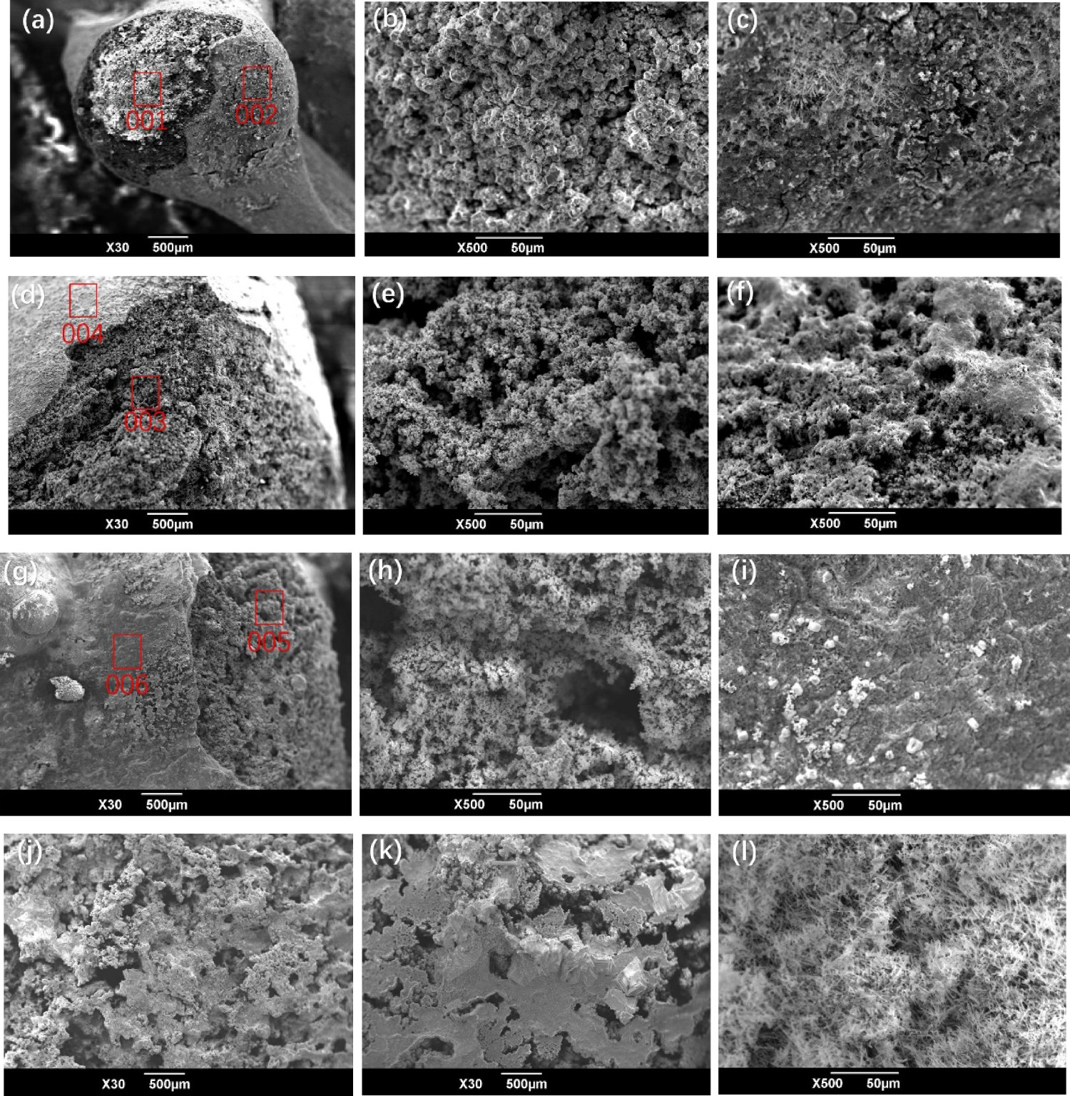
EDS analysis for different corrosion layer (at.-%).
The experimental data indicate that the role of Cl− ion in high temperature and pressure consisted of two aspects. The first was the salting-out effect. Ions from the salt attracted water molecules to ‘solvate’ the ions when an ionic salt (i.e. NaCl) was added into water. The affinity of O2 molecules with water was weakened. The concentration of dissolved O2 was eliminated in polar water, which was unfavourable for the corrosion of P110 steel. The other aspect was the increasing number and size of holes in corrosion scales because of the dissolution of product FeCl x . In an Fe–O2–H2O system with high Cl− concentration, OH− and Cl− ions adsorbed on the surface of metal when steel was immersed in a solution. The product Fe(OH)2 was formed in the region adsorbed by OH− ion, and product FeClx formed in the region adsorbed by Cl− ion. When product FeCl x was dissolved into water, many passages were left in corrosion scales composed of Fe(OH)2/Fe(OH)3. The O2(aq) easily diffused into the solution/metal interface zone vis these passages. The role of concentration polarisation was weakened, and the corrosion rate of steel decreased. Concentration polarisation was the main cause of the serious corrosion of Fe in the O2–Cl−–H2O system at high temperature and pressure.
Conclusion
In this work, the effect of air injection pressure, temperature and Cl− concentration in injection water on the corrosion behaviour of oil tube steel was analysed through a simulated air-assisted steam injection process.
The high corrosion rate for oil tubes in a downhole environment arose from the concentration polarisation due to the loose deposition structure of iron oxides. The compacted phase Fe3O4 slightly relieved the corrosion from injection water.
Air injection pressure strongly influenced the corrosion of oil tube steel. The corrosion rate of P110 steel specimen increased from 32.07 to 72.83 mm per year when air pressure increased from 5 to 20 MPa.
The trend of corrosion rate and temperature in air-saturated injection water was a reversed ‘V’ curve. The highest corrosion rate occurred at 170°C for the P110 specimen in air-saturated hot steam and injection water.
The Cl− ion in the Fe–O2–Cl−–H2O corrosion system decreased the O2 solubility through the salting-out effect, and weakened the O2 concentration polarisation via the dissolution of FeClx in corrosion products. The corrosion rate of the P110 steel decreased as Cl− concentration increased.
From an engineering perspective, air injection is an effective technique for high Cl− concentration wells. In addition, air injection pressure for increasing oil recovery ratio should balance the corrosion rate of oil tube. A temperature of 170°C should be avoided under 10 MPa injection air pressure as it is only suitable for the highest corrosion rate. Periodic removing corrosion scales are necessary to prevent downhole tubular goods from under-deposit corrosion.
Footnotes
Disclosure statement
No potential conflict of interest was reported by the authors.