
Abstract
ABSTRACT
The application of biodegradable Magnesium (Mg) alloy implants is limited due to their insufficient corrosion fatigue resistance. This work investigated the influence of double extrusion on the microstructure, mechanical properties and corrosion fatigue behaviour of Mg–Zn–Y–Nd alloy. The results showed that, after double extrusion, the texture intensity was significantly weakened and a more uniform microstructure with fine grain size was obtained. The double extruded alloy showed improved mechanical properties with a yield strength of 196.5 MPa, an ultimate tensile strength of 241.8 MPa and an elongation up to 29.7%. As compared to that of single extruded Mg–Zn–Y–Nd alloy, the fatigue tests indicated that double extrusion improved the fatigue strength of the alloy by 23% in air and 20% in simulated body fluid. Based on the results, the mechanisms of fatigue and corrosion fatigue of double extruded Mg–Zn–Y–Nd alloy were presented.
Introduction
Traditional metallic stents, made of stainless steel, cobalt–chromium, titanium alloys and other inert materials, are frequently used in clinical treatment of blockage of arteries due to their excellent mechanical properties, high corrosion resistance and good biocompatibility [1,2]. However, the endothelial dysfunction and chronic inflammatory reactions in the human body caused by these permanent implant materials influence the service properties of these traditional stents [3,4]. The ideal service duration of stents in human body should be consistent with the reconstruction time of vascular compliance, which generally takes 6-12 months [5 7]. After this period, the presence of stents becomes meaningless and even harmful. The application of biodegradable stents is proposed under this circumstance and has received considerable attention in recent decades. Mg alloys are regarded as the suitable candidate for absorbable stents because of their superior biocompatibility and biodegradability [8,9]. In addition, the released Mg2+ during the corrosion of Mg implants could be used to treat acute myocardial infarction due to its anti-arrhythmic effect [10 12]. However, Mg alloys are prone to stress corrosion and corrosion fatigue under the combined action of cyclic mechanical loading and corrosive physiological environment. It probably reduces the fracture resistance significantly and results in severe or catastrophic failure of the implants [13,14]. Consequently, it is necessary to adopt some appropriate methods to avoid such incidents.
Alloying is one of the most effective measures to improve the mechanical properties and corrosion resistance of Mg alloys. A number of Mg alloys, such as Mg–Y–RE (WE series) [15], Mg–Zn–Ca (ZX series) [16], Mg–Zn–Y–Nd [17] and Mg–Nd–Zn–Zr (JDBM) [18], have been used for biomedical implant applications. Among them, rare earth containing Mg alloys have attracted increasing attention because of their high mechanical properties, improved corrosion resistance and acceptable biocompatibility [19,20]. In addition to alloying, severe plastic deformation (SPD) techniques have also been performed to improve the service properties of Mg alloys by adjusting the microstructure. In recent years, several different SPD methods have been proposed. Zhang et al. reported that a biodegradable Mg–Nd–Zn–Zr alloy reached a high strength (ultimate tensile strength up to 300 MPa, elongation up to 32%) and enhanced corrosion resistance by double extrusion [21]. Wu et al. found that cyclic extrusion compression (CEC) treated Mg–Zn–Y–Nd alloy exhibited high strength (ultimate tensile strength up to 303 MPa, elongation up to 30.2%) and low corrosion rate [22]. Gao et al. showed that high pressure torsion (HPT) processed Mg–Zn–Ca alloy exhibited homogeneous corrosion and the corrosion current density was reduced by two orders of magnitude compared with that of the as-cast counterpart [23]. Fintova and Kunzb proposed that Equal Channel Angular Pressing (ECAP) treatment increased the tensile properties of the as-cast AZ91 alloy and significantly improved the low-cycle fatigue life [24].
The as-cast Mg alloys will not be used as implants materials in the real applications due to its poor mechanical properties and corrosion resistance. Thus, the study on their corrosion fatigue behaviour is of little significance. In recent years, a variety of published works focused on the corrosion fatigue of the extruded biodegradable Mg alloys. Gu et al. found that a fatigue strength of 110 MPa at 107 cycles was obtained in air for the extruded WE43 alloy, however, it decreased to 40 MPa at 107 cycles in simulated body fluid (SBF) [15]. Bian et al. conducted relevant studies on the extruded HP–Mg, Mg–1Ca and Mg–2Zn–0.2Ca alloy, and the results indicated that their fatigue strength was 90 MPa at 107 cycles in air compared to 52, 70 and 68 MPa at 4 × 10⁶ cycles in SBF [25]. Our previous work has investigated the corrosion fatigue behaviour of single extruded Mg–Zn–Y–Nd alloy and showed that the fatigue limit was 65 MPa at 107 cycles in air and the corrosion fatigue strength was 50 MPa at 3.5 × 10⁶ cycles [26]. Meanwhile, these investigations also demonstrated that the fatigue crack sources in air generally originated from the microstructural defects in the samples, and the fatigue crack sources initiated from the corrosion pits in SBF [15,25,26]. However, there are few studies about the investigation of the influence of SPD on corrosion fatigue properties of biodegradable Mg alloys, and the mechanism of fatigue crack initiation in SPD processed alloys is still not fully understood. In this work, the effect of double extrusion on the microstructure, mechanical properties and corrosion fatigue resistance of Mg–Zn–Y–Nd alloy was investigated. Based on the obtained results, the mechanisms of fatigue and corrosion fatigue of double extruded Mg alloys were also discussed.
Experimental procedure
Materials
The single extruded Mg–Zn–Y–Nd alloy bars were cut into billets (48 mm in diameter and 30 mm in length) for double extrusion. Before double extrusion, these billets were wrapped in tin foil and solution treated at 450°C for 72 h in a Muffle furnace (Shanghai Yongqing Experimental Apparatus Co. Ltd, YQK800-60). Table 1 lists the chemical composition of this alloy. The extrusion parameters are listed in Table 2. Figure 1 shows the schematic illustration of the mould for double extrusion. A water tank was placed under the mould in order to rapidly cool the double extruded rods.
The schematic illustration for double extruded mould. Chemical composition of Mg–Zn–Y–Nd alloy. Extrusion parameters of Mg–Zn–Y–Nd alloy.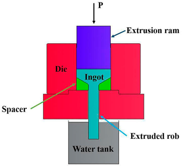

Microstructural observation
Samples for microstructural observation were cut along their longitudinal section, grounded with 100-1200 grit SiC papers and polished up to mirror-like surface with 0.25 µm diamond grinding paste. The distribution of second phases was observed using a scanning electron microscope (SEM; FEI Quanta 200). The polished samples were electrolytic polished with perchloric acid solution at −30°C. The electron backscatter diffraction (EBSD) measurements were conducted using a scanning electron microscope (Zeiss) equipped with HKL channel 5 software.
Mechanical characterisation
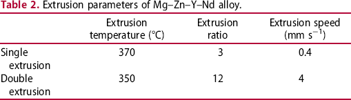
Tensile tests were conducted on an MTS machine (Bionix 370.2) with a tensile rate of 0.5 mm min−1 at ambient temperature. The dog-bone samples with the gauge length of 20 mm and the diameter of 5 mm were used in the tests (Figure 2). The stress corresponding to 0.2% plastic deformation is taken as the yield strength. After tensile tests, the fractured surfaces were observed using a scanning electron microscope (SEM; FEI Quanta 200). Vickers hardness (HV) tests were performed using a microhardness tester (HXD-1000TMSC/LCD) with a load of 200 g and a dwell time of 10 s. The bulk samples with the length of 10 mm, the width of 8 mm and the height of 8 mm were used in the tests, and the values of HV were shown using the average of ten points randomly selected on the surface of samples.
Tensile test samples (dimensions are in mm).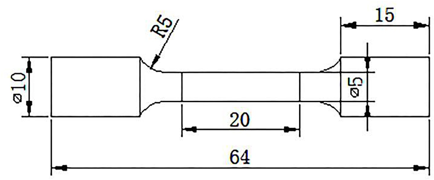
Fatigue and corrosion fatigue testing
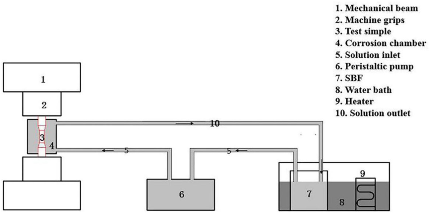
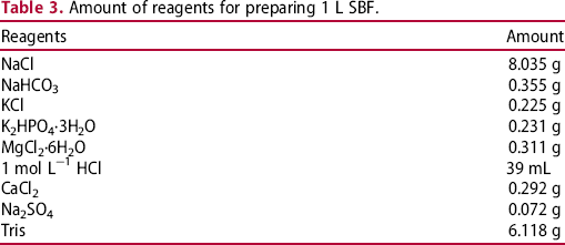
Dog-bone samples with 5 mm diameter and 20 mm gauge length were employed in fatigue tests (Figure 3). Tension-compression fatigue tests were performed on a MTS machine (Bionix 370.2) in the form of sinusoidal wave with a frequency of 5 Hz and a stress ratio (R) of −1 in air and SBF. The schematic diagram of the testing device for corrosion fatigue is shown in Figure 4. A sealed corrosion chamber was attached to the sample to ensure that the exposed surface was immersed in the SBF at a constant flow rate. In this study, the temperature of SBF (2 L in total volume) was maintained at 37 ± °C using a water bath. The flow rate of SBF was adjusted to 30 ml min−1 by a peristaltic pump, and the SBF was replaced every 24 h. Table 3 lists the composition of SBF with an initial pH = 7.40 ± 0.02.
Fatigue test samples (dimensions are in mm). Schematic diagram of the corrosion fatigue experimental setup. Amount of reagents for preparing 1 L SBF.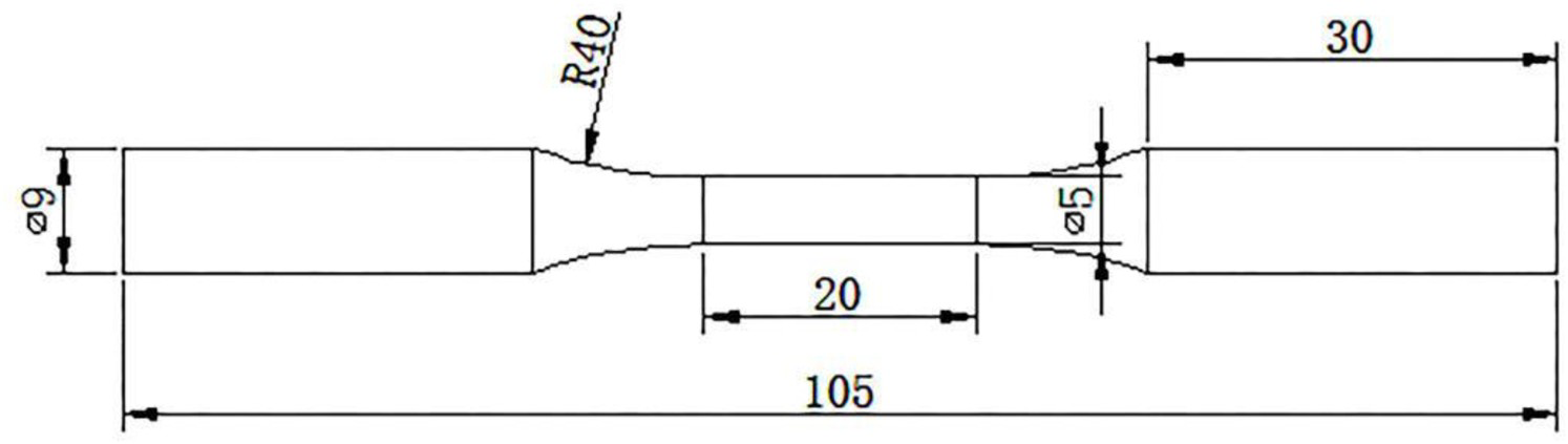
Fatigue fractography
The fractured sample surfaces of fatigue testing were examined using a scanning electron microscope (SEM; FEI Quanta 200). In order to remove the corrosion products from the fatigue fractured surfaces, samples tested in SBF were immersed in 20 wt-% CrO3 and 10 wt-% AgNO3 solution [16] for 20 s, then ultrasonically cleaned in ethanol and dried by warm flowing air.
Results
Microstructure
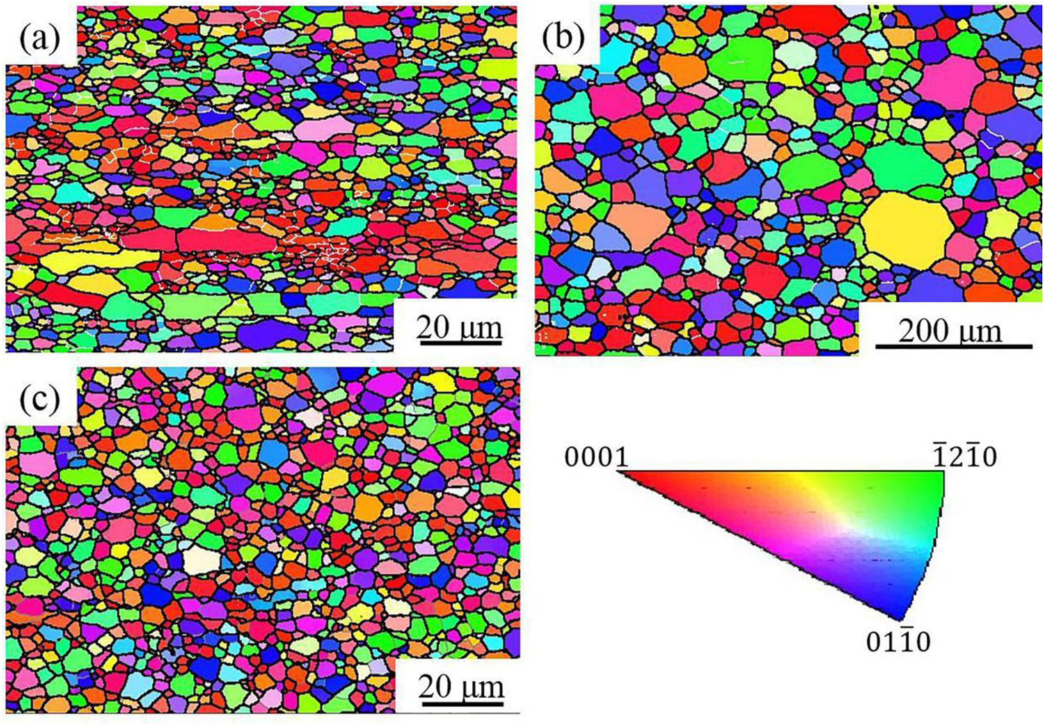
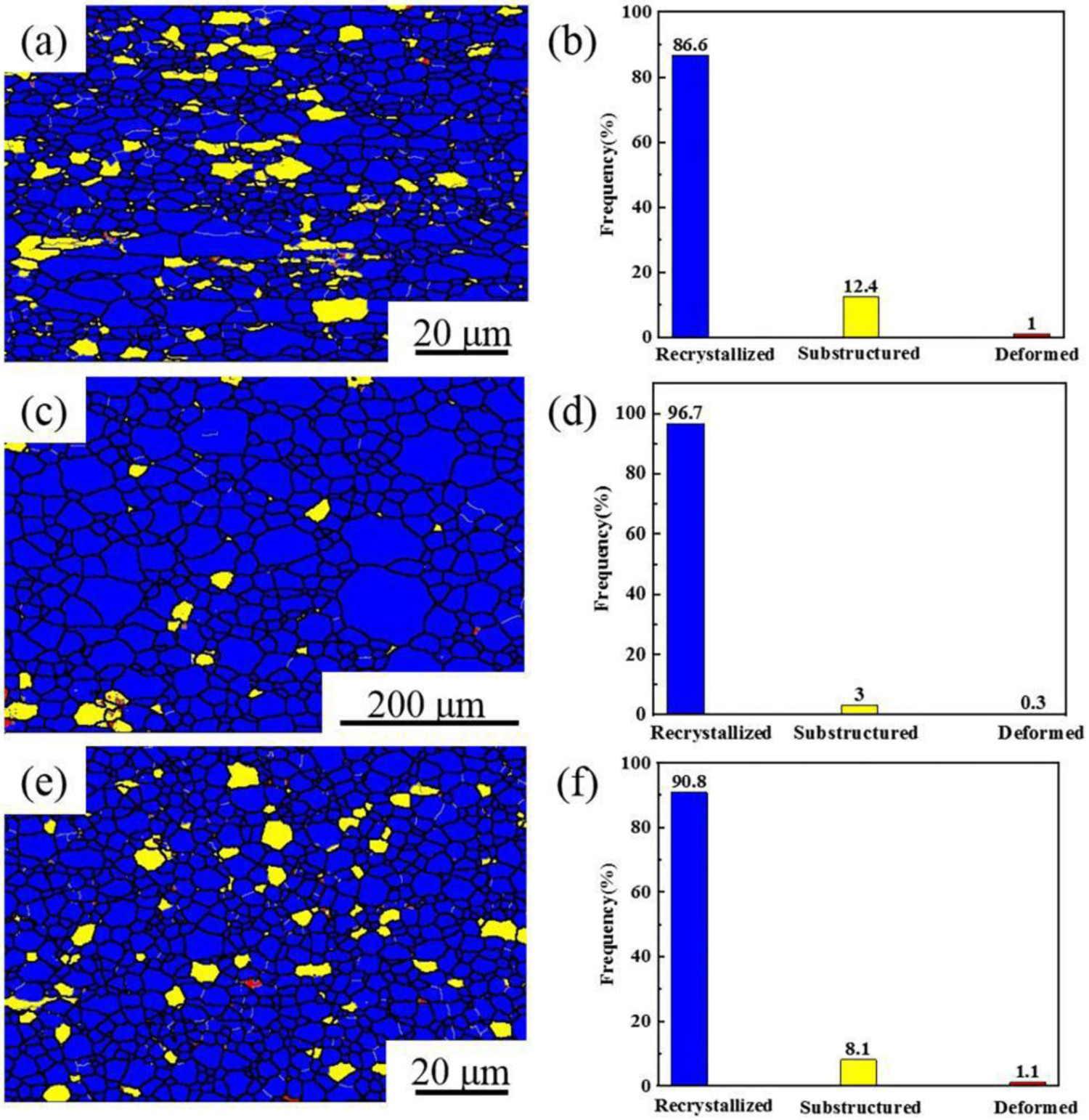
The continuously distributed second phases were parallel to extrusion direction (ED) in single extruded samples (Figure 5(a)). After solution treatment, the linear distribution of second phases was greatly reduced and most of the second phases were dissolved in Mg matrix (Figure 5(b)). While for the double extruded samples, the uniformly distributed second phases were observed (Figure 5(c)). Figure 6 shows the grain orientation maps of Mg–Zn–Y–Nd alloy. Different colours denoted different crystallographic orientations of the crystal grains corresponding to the stereographic triangle. The grain sizes of single extruded samples were not homogeneous. It could be found that the grain size was in the range of 1-25μm (Figure 6(a)). After solution treatment, the grains were completely equiaxial and the grain size varied greatly from 6 to 132 μm (Figure 6(b)). For the double extruded samples, uniform microstructures with fine grains were formed, and the average grain size reduced to 4.1 ± 2.0 μm (Figure 6(c)). Figure 7 displays the recrystallisation diagram and the different colours represent the different grain states. The blue, red and yellow colour indicated the recrystallised grains, deformed grains and the substructured grains, respectively.
The distribution of second phases of Mg–Zn–Y–Nd alloy: (a) single extrusion, (b) solution treatment, (c) double extrusion. EBSD IPF maps of Mg–Zn–Y–Nd alloy: (a) single extrusion, (b) solution treatment, (c) double extrusion. Images of recrystallised fraction of Mg–Zn–Y–Nd alloy: (a, b) single extrusion, (c, d) solution treatment, (e, f) double extrusion.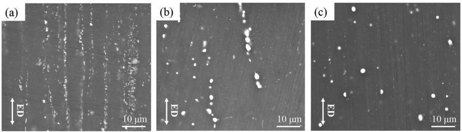
The texture evolution of Mg–Zn–Y–Nd alloy is displayed in Figure 8. The single extruded samples contained the basal texture component and the Texture evolution of Mg–Zn–Y–Nd alloy: (a, c, e) (0001) and  plane was perpendicular to ED (Figure 8(a)). After solution treatment, it was apparent that the basal texture component nearly disappeared (Figure 8(c)). As compared to that of single extruded samples, the double extruded samples contained the weaker basal texture component and the corresponding inverse pole figure exhibited a rare earth texture component
  parallel to ED (Figure 8(e,f)). The texture intensity of Mg–Zn–Y–Nd alloy after single extrusion, solution treatment and double extrusion were 4.87, 2.66 and 2.62, respectively.
 pole figures and (b, d, f) inverse pole figures parallel to ED.
Mechanical properties
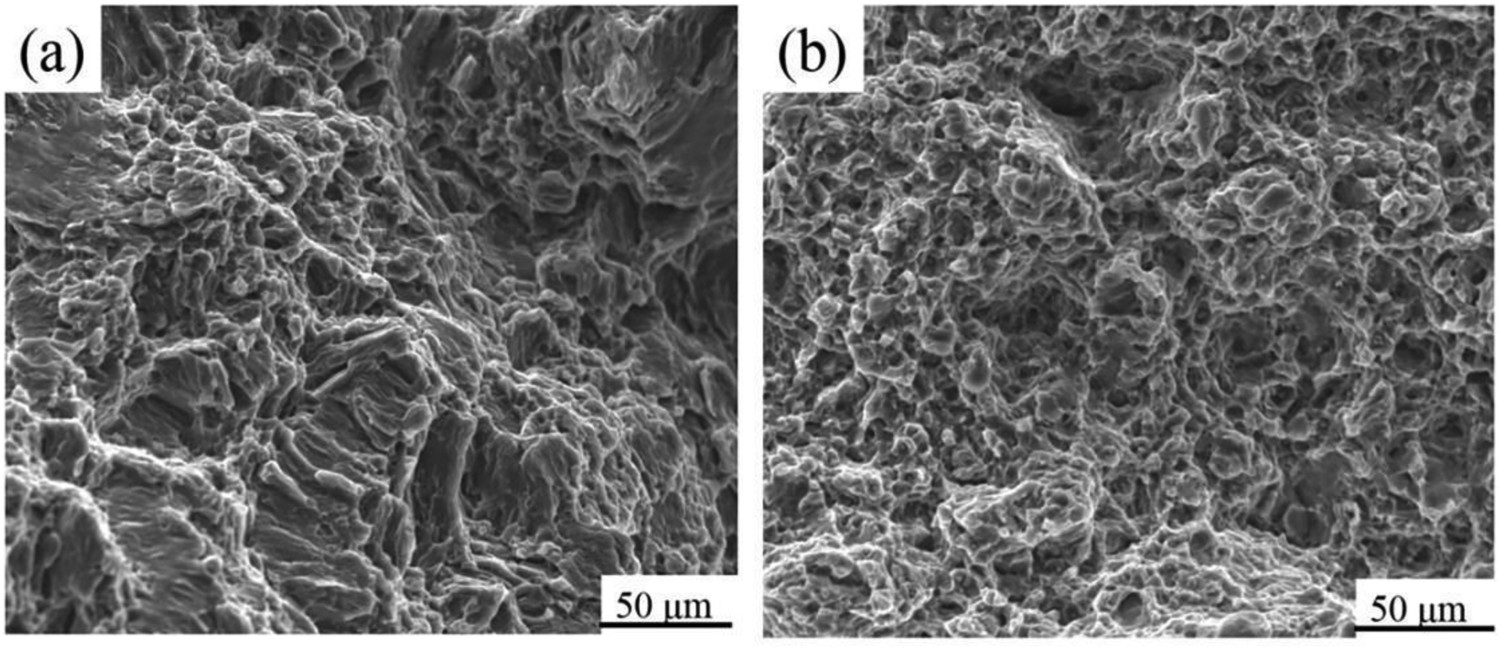
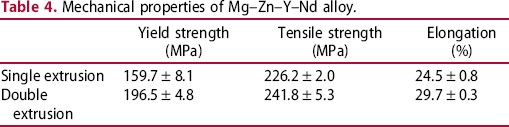
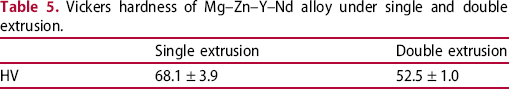
Figure 9 shows the tensile stress–strain curves of Mg–Zn–Y–Nd alloy tested at ambient temperature. The specific mechanical properties are summarised in Table 4. The yield strength, ultimate tensile strength and elongation of single extruded samples were 159.7 ± 8.1 MPa, 226.2 ± 2.0 MPa and 24.5 ± 0.8%, respectively. Compared with single extruded samples, the double extruded samples exhibited noticeable improvement in yield strength, ultimate tensile strength and elongation. The yield strength, ultimate tensile strength and elongation of double extruded samples were 196.5 ± 4.8 MPa, 241.8 ± 5.3 MPa and 29.7 ± 0.3%, respectively. Figure 10 shows the morphologies of the tensile fractured surfaces of samples. For the single extruded samples, there were plentiful cleavage planes and some dimples, as depicted in Figure 10(a), which indicated the combination of cleavage fracture and ductile fracture. This agreed well with the decreased ductility shown by the tensile tests in Figure 9 (red curve). After double extrusion, a large number of dimples could be observed in Figure 10(b), which proved that the double extruded samples presented a typical ductile fracture mode. Table 5 lists the hardness of Mg–Zn–Y–Nd alloy under two extrusion conditions. It could be found that the hardness of double extruded samples was lower than that of single extruded samples.
The stress–strain curves of extruded samples under single and double extrusion. The tensile fracture morphologies of extruded samples: (a) single extrusion, (b) double extrusion. Mechanical properties of Mg–Zn–Y–Nd alloy. Vickers hardness of Mg–Zn–Y–Nd alloy under single and double extrusion.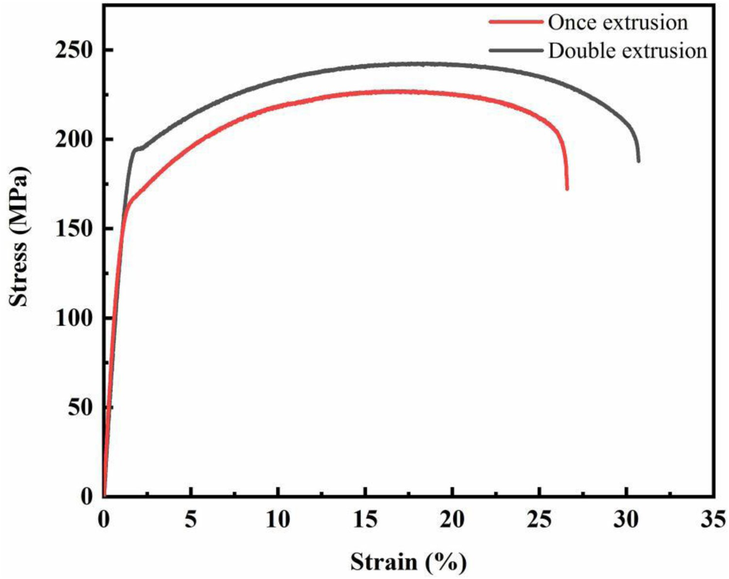
The S–N curves
The stress–life (S–N) curves of single extruded and double extruded samples tested in air and SBF at 37°C are plotted in Figure 11. It showed that the fatigue limit of double extruded samples at 107 cycles was 80 MPa in air and 60 MPa at 3.5 × 10⁶ cycles in SBF. The air fatigue strength at 107 cycles and corrosion fatigue strength at 3.5 × 10⁶ cycles of double extruded samples showed around 23% and 20% higher than those of the single extruded ones. The fatigue limit of samples in SBF was much lower than those tested in air due to the presence of corrosive medium. Moreover, the fluid flow of corrosive media also influences Mg corrosion. It was reported that Mg alloy showed different degradation behaviour in the corrosive media under static and dynamic conditions. Pits formed over the surface of samples and filiform corrosion occurred during static tests, and the surface of samples showed localised corrosion under high shear stress (caused by the liquid flow) [27].
The S–N curves for Mg–Zn–Y–Nd alloy tested in air and SBF (black arrows correspond to run-out samples) (a) single extrusion [26], (b) double extrusion.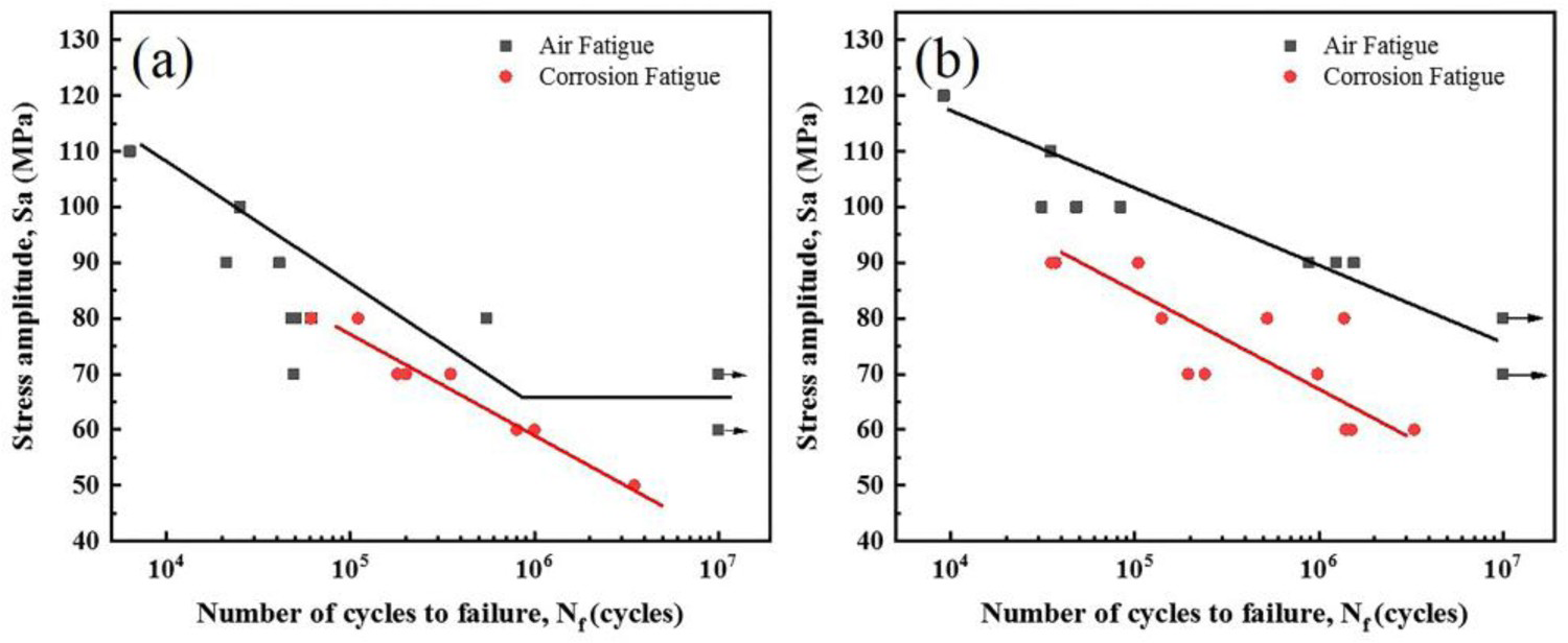
Fatigue and corrosion fatigue
The typical morphologies of fractured surfaces of double extruded alloy in air are shown in Figure 12. The second column in Figure 12 displays the overall fractured surfaces of samples that failed under different stress amplitudes, in which the white arrows show the direction of fracture extension. Three distinct zones, namely the crack initiation zone, the steady crack propagation zone and the finally overload zone, could be observed on the overall fractured surfaces. The third and fourth columns are the amplified details derived from the crack initiation zones and the crack propagation zones corresponding to the second column, respectively. It could be found that the samples generally had one fatigue crack source in air, and the fatigue cracks initiated from the microstructural defects, such as microcracks (Figure 12(a Typical fracture surfaces of Mg–Zn–Y–Nd alloy under double extrusion in air at room temperature. (a), (b) and (c) are the overall fractographic images. Column (a1, b1, c1), column (a2, b2, c2) and column (a3, b3, c3) are the amplified images derived from the crack initiation zones, the crack propagation zones and mechanical overloading zones corresponding to the second column (a, b, c), respectively.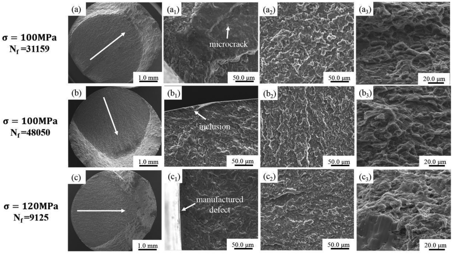
Figure 13 lists the typical morphologies of fractured surfaces of the corroded double extruded samples after removing the corrosion products. Different from the fatigue crack sources in the air, multiple fatigue crack sources were found on samples that tested in SBF. The failure of samples could be attributed to the formation of the microcracks (Figure 13(a1,c1)) and corrosion pits (Figure 13(b1)). The features of the crack propagation zones and finally overload zones on fatigue fractured surfaces in SBF were very similar to those tested in air.
Typical fractured surfaces of Mg–Zn–Y–Nd alloy under double extrusion in SBF at 37°C. (a), (b) and (c) are the overall fractographic images. Column (a1, b1, c1), column (a2, b2, c2) and column (a3, b3, c3) are the amplified images derived from the crack initiation zones, the crack propagation zones and mechanical overloading zones corresponding to the second column (a, b, c), respectively.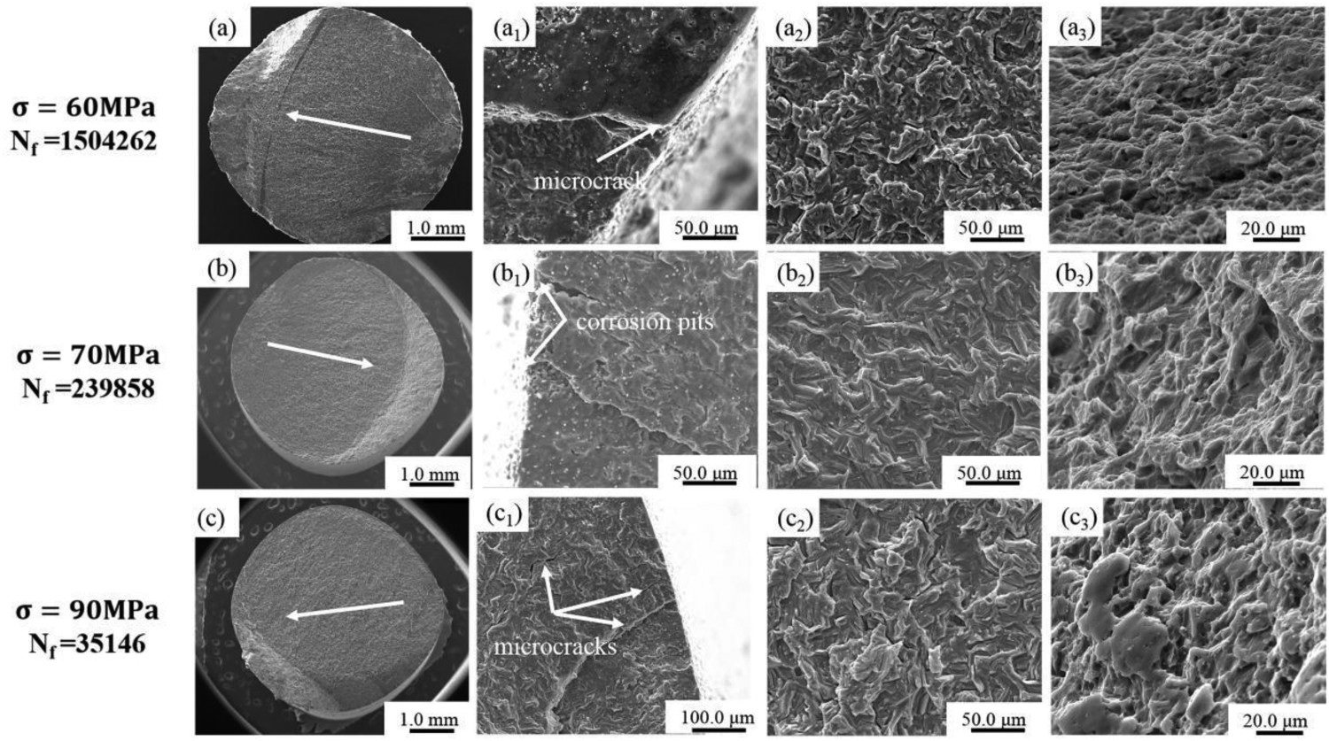
Discussion
Microstructure and mechanical properties
The microstructure of Mg–Zn–Y–Nd alloy under single extrusion is not homogeneous. Both large elongated grains and small equiaxial grains could be observed in the alloy. Previous study suggested that the formation of large elongated grains were related to the (0001)  slip system in the extruded alloys [28]. This causes the crystal grains being arranged along the
  crystal direction with their c-axis perpendicular to the ED. These grains are in a favourable orientation during extrusion deformation process, which leads to greater strain without twinning and potential hardening in the basal slip system [21]. As a result, these grains have insufficient deformation storage energy to trigger dynamic recrystallisation (DRX). The texture intensity is weakened after solution treatment due to the occurrence of static recrystallisation and grain growth during this period. The preferential growth of crystal grains results in the deviation of (0001) plane from the ED. After double extrusion, the grains are significantly refined, which is attributed mainly to the occurrence of more complete DRX (dynamic recrystallised fraction of 90.8% after double extrusion compared with 86.6% after single extrusion). Meanwhile, artificial water cooling is an effective approach to inhibit the growth of the DRXed grains of samples after double extrusion [29]. The refined grain size helps the improvement of strength since the movement of locations is hindered by increased grain boundaries. In addition, the dispersed distribution of the second phase particles after double extrusion also contributes to the increase in strength. The addition of rare earth elements in Mg alloys can effectively modify the extrusion texture and form rare earth texture under certain conditions. It was reported that the rare earth texture could enhance the isotropy and the plastic deformation ability of Mg alloys by weakening other texture components [28,30]. Compared with single extrusion, the texture intensity is significantly weakened, and the rare earth texture
  is formed parallel to ED after double extrusion. Hence, the improved ductile of Mg–Zn–Y–Nd alloy under double extrusion could be ascribed mainly to the fine grains and the occurrence of rare earth texture component. It is worth noting that the hardness of Mg–Zn–Y–Nd alloy decreases with the decrease of grain size, because the basal texture weakening plays a leading role in hardness reduction during the double extrusion process. As reported by Sahoo et al., the basal grains possessed a higher hardness value than the non-basal counterparts [31].
Fatigue and corrosion fatigue
When tested in air, fatigue samples are under axial alternating stress. The microstructural defects such as micropores, microcracks and inclusions, or the surface defects would lead to the stress concentration and then result in the initiation of fatigue crack sources [32,33]. Twin boundaries and slip bands could also be acted as crack source initiators when samples are free of defects [34]. For the smooth samples, the crack formation life accounts for about 90% of the total fatigue life, while the crack propagation life only accounts for 10% [26]. Once the fatigue crack source is formed, it would extend rapidly until the sample fails. The double extruded Mg–Zn–Y–Nd alloy has a longer fatigue life than the single extruded ones under the same stress amplitude (as depicted in Figure 11). This is related to the decrease of grain size and the disperse distribution of second phases after double extrusion, which inhibits the crack initiation and increases the number of barriers to the early propagation of cracks [35]. A similar result was obtained by Horstemeyer et al. that the fatigue life of AZ91E alloys increased with the decrease of grain size [36]. At the same time, the fine and uniform grains lead to a large number of dimples in the finally overload zones of fatigue samples.
When tested in SBF, samples are subjected to the simultaneous action under cyclic mechanical loading and corrosive medium. In addition to the intrinsic properties of the tested materials, the external environment also affects the fatigue life of samples. At high stress levels, the microstructural defects could cause significant stress concentration, where the fatigue cracks would be initiated preferentially before corrosion pits reach the critical size. As shown in Figure 13(c The side of the crack initiation of corrosion fatigue fractured samples under different stress amplitude. (a) 70 MPa stress with 239,858 cycles, (b) 60 MPa stress with 1,504,262 cycles.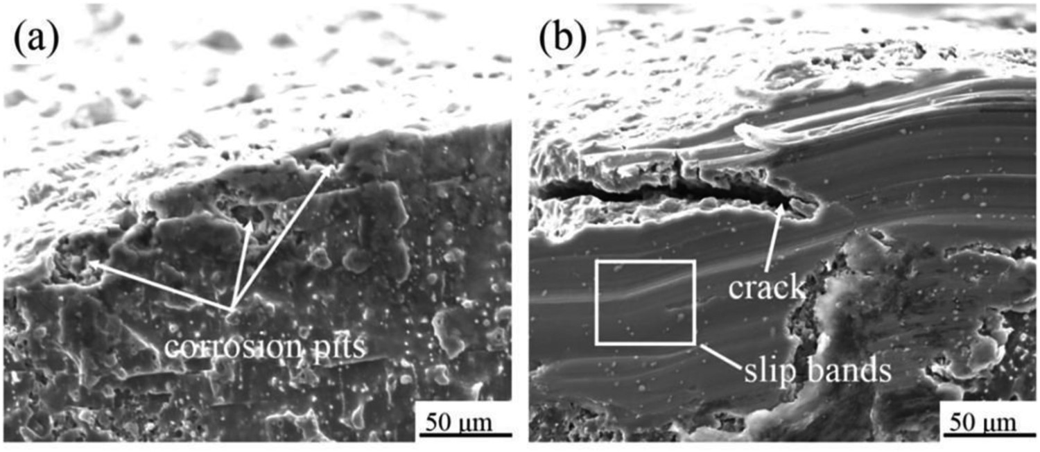
The grain orientation is an important factor in influencing the corrosion resistance of Mg alloys, and the corrosion of Mg alloys can directly affect its corrosion fatigue performance. It was reported that the corrosion resistance of AZ31 alloy increased with the decreased (0001) plane texture intensity [39]. Moreover, the corrosion product layer formed on the basal plane has a better protective effect than that on non-basal planes [40]. However, the corrosion fatigue strength of double extruded Mg–Zn–Y–Nd alloy is higher than that of the single extruded alloy. The influence of the fine and uniform microstructure on corrosion fatigue strength should be considered here. First, similar to that in the air, the resistance of corrosion fatigue crack initiation and growth increases with increasing the area of grain boundaries by grain refinement. Second, grain refinement reduces the mismatch between the corrosion product film and Mg matrix, and thus enhances the interfacial cohesive force [41]. Thirdly, the uniform microstructure reduces localised corrosion and avoids the generation of deep corrosion pits, thereby reduces the stress concentration effect and prolongs the generation of the fatigue crack sources. Hence, the positive effect of fine and uniform microstructure on corrosion fatigue strength is greater than the negative effect of texture weakening.
Mechanisms of fatigue and corrosion fatigue
Based on the obtained results, the mechanisms of fatigue and corrosion fatigue of Mg–Zn–Y–Nd alloy are generally discussed in this section. Samples after single and double extrusion are inevitably consisting of some microstructural defects (Figure 15(a1)). The microcracks preferentially forms in these sites with large defects of samples under the condition of cyclic mechanical loading due to the stress concentration (Figure 15(a The mechanisms of fatigue and corrosion fatigue for Mg–Zn–Y–Nd alloy under single and double extrusion.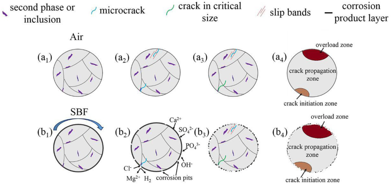
A corrosion product layer will be formed on the surfaces of Mg alloys when they are immersed in SBF (Figure 15(b1)). Local breakdown of the corrosion product film on Mg alloy surfaces could occur under cyclic mechanical loading, resulting in localised corrosion and the formation of corrosion pits (Figure 15(b2)). Meanwhile, the chloride ion in the corrosive medium is harmful to the corrosion fatigue strength, which accelerates Mg alloys corrosion and increases the sensitivity of stress corrosion [16,27,33,42]. Accelerated corrosion under cyclic mechanical loading is attributed to stress corrosion. Besides, corrosion pits could become the initiator of stress concentration. With the increase of exposure time in corrosive medium, new corrosion pits would be formed continuously, and part of them might grow to critical dimensions, resulting in the generation of fatigue crack sources (Figure 15(b
Conclusion
Compared with single extrusion, a fine and uniform microstructure was obtained and the texture intensity was significantly weakened for the Mg alloy after double extrusion. The double extruded alloy exhibited improved mechanical properties with a yield strength of 196.5 MPa, an ultimate tensile strength of 241.8 MPa and an elongation up to 29.7%. The tensile fractured surfaces of single extruded alloy displayed a combination of cleavage fracture and ductile fracture, while the double extruded alloy showed a typical ductile fracture. The fatigue strength of double extruded Mg–Zn–Y–Nd alloy was 80 MPa at 107 cycles in air compared to that of 60 MPa at 3.5 × 10⁶ cycles in SBF. The double extruded samples showed better performance on fatigue and corrosion fatigue than that of single extruded samples due to the homogenisation and refinement of microstructure. The formation mechanisms of the fatigue crack source in single extruded and double extruded samples were similar, namely the fatigue crack sources of samples tested in air and SBF generally originated from the microstructural defects and corrosion pits, respectively.
Footnotes
This work was supported by the Key Projects of the Joint Fund of the National Natural Science Foundation of China under Grant No: U1804251 and the National Key Research and Development Program of China under Grant No: 2018YFC1106703 and 2017YFB0702504.
Disclosure statement
No potential conflict of interest was reported by the author(s).