
Abstract
The corrosion behavior and mechanism of CoCrFeNi HEA under AC application were systematically studied in 3.5 wt.% NaCl solution containing different concentrations of NaHSO3. The results showed that the existence of HSO3 − increased the defect density within the passivation film on the surface of the HEA. With the increase of HSO3 − concentration, the passivation zone became narrow, Ep shifted negatively, and ip increased, which indicated that the corrosion resistance of the HEA was weakened. When the HSO3 − concentration increased to 0.1 M, a clear transition zone appeared, indicating that the increase in concentration reduced the passivity of the HEA, and its corrosion behavior changed from the typical passivation characteristic to the activation state with increasing iAC. The imposed AC promoted the nucleation of metastable pitting, which was indicated by a remarkable increase in the average pitting number density (Navg) from 5 to 17 mm−2 with the enhancement of iAC.
GRAPHICAL ABSTRACT
Highlights
Corrosion behaviour of CoCrFeNi HEA with imposed AC was studied in a SO2-polluted marine environment. Metastable pitting behaviour was investigated in NaCl solution containing With increased The HEA changed from passivation characteristic to activation state with the increase of applied iAC. The initiation of pitting was due to the selective dissolution of Ni element, and the selective dissolution of Cr, Fe, Co and Ni elements occurred inside the oxide.
 at different iAC.
 concentration, the stability and protective ability of passive film were weakened.
Introduction
Traditional alloys are generally designed based on one main metal component plus a small number of other metal elements to improve or obtain the desired properties, which can not satisfy the application requirements of some complex industrial environments [1,2]. In addition, the drawback of this design method is that some complex compounds or unpredictable phase compositions can be generated. Nowadays, Ye et al. [3] proposed a new concept of alloy design, that is, the alloy containing multiple primary elements has simple structures with fewer phase compositions. These alloys, known as entropy-based alloys, have attracted a lot of attention from researchers because of their superior mechanical properties [4], thermal stability [5] and wear resistance [6,7]. Among them, the equiatomic CoCrFeNi high-entropy alloy (HEA) is one of the most representative HEAs and has achieved some research results. Salishchev et al. [8] investigated the metallographic structure and mechanical properties of CoCrFeNi alloy under solidification and annealing conditions. The results showed that the HEA had a single-phase face-centered cubic (FCC) structure, and the addition of the V element caused significant strengthening accompanied by plasticity deficiency. Sathiyamoorthi et al. [9] compared the change in thermal stability of the CoCrFeNi HEA under milling and sintering conditions, demonstrating its excellent high-temperature properties. Huo et al. [10] showed the advantage of CoCrFeNi HEA in replacing conventional alloys in critical loading applications, and the results demonstrated that the HEA exhibited a good combination of high strength and plasticity under tensile deformation at high strain rates.
Based on the outstanding mechanical performances of CoCrFeNi HEA, it can be used in practical engineering structures. In engineering applications, the anti-corrosion property of materials is also an important index to evaluate the service life of equipments, and the current studies on the corrosion behaviour of CoCrFeNi HEA are very limited [11,12]. Liu et al. [13] reported that the addition of Ge element inhibited pitting nucleation and enhanced anti-corrosive performance. Hsu et al. [14] investigated that FeCoNiCr HEA with FCC structure was easy to passivate in NaCl solution, and even exhibited better anti-corrosion performance than 304L stainless steel. Zhu et al. [15] explained the effect of microstructure and chemical composition of CoCrFeNi HEA on the electrochemical properties in NaCl solution and proposed that the high content of Cr in the HEA promoted the formation of the passivation layer. Wu et al. [16] explored that a non-equiatomic FeNiCoCr possessed higher corrosion resistance than 316L SS in 0.1 M H2SO4 solution. The as-homogenised HEA possessed a very low passivation current density (ip) of 4.7224 × 10⁻⁶ A/cm2.
In recent years, researchers have extensively studied the corrosion behaviour of various alloys in the simulated marine environment [17,18], and the results show that Cl− can adsorb in the weak position of the passivating film on the surface of the materials, destroying the stability and integrity of the film and inducing pitting nucleation. With the extensive development of marine resources, in some regions, due to industrial pollution, the marine atmosphere contains a certain amount of SO2 and SO2 dissolves in seawater to form  , so the alloys applied in the offshore platforms and marine construction in the splashing environment of seawater are susceptible to more serious corrosion [19,20]. On the one hand,
  can also be adsorbed in the active sites of the passivation film and combined with Cl− to accelerate the corrosion process; on the other hand, the ionisation effect of
  is greater than the hydrolysis effect, producing more H+ and increasing the local acidity, which is destructive to the metals [21]. However, there is no research report on the corrosion behaviour of CoCrFeNi HEA in SO2-pollution seawater solution. Therefore, the study of the corrosion behaviour of the HEA in the industrial pollution environment is an important guiding value for its application in engineering. Moreover, some coastal areas and offshore platforms are disturbed by alternating current (AC) due to the surrounding high-voltage transmission lines or electric equipments [22,23], which may promote the corrosion of CoCrFeNi HEA employed in these cases. Thus, it is necessary to study the corrosion behaviour of the HEA with AC interference in NaCl solution polluted by various levels of SO2.
In the current paper, the effect of  and AC on the passivation film and corrosion behaviour of CoCrFeNi alloy in a simulated marine environment was investigated by electrochemical tests, surface analysis techniques and immersion corrosion test. In addition, the effect of AC on the initiation and development of metastable pitting was statistically analysed.
Experimental
Materials and test solution
The material used for the tests was an equiatomic CoCrFeNi HEA ingot prepared from elements with purity above 99.9% wt.% by vacuum arc melting. It was machined into 10 × 10 × 3 mm specimens for the study of the electrochemical behaviour, and the remaining surfaces were sealed with epoxy resin except for a 10 × 10 mm2 surface. After sanding from 180 to 2000 grit using SiC sandpaper, they were cleaned sequentially with anhydrous ethanol and deionised water in turn, dried and set aside. However, for the study of metastable pitting, the specimen was filamentary with a cross-sectional area of 0.1 mm2 to avoid the inability to induce metastable pitting due to the current superposition.
In this work, the test solution was 3.5 wt.% NaCl solution with different concentrations of NaHSO3 for simulating SO2-polluted marine environment. All measurements were carried out at a constant temperature of 30°C.
Microstructure analysis
The CoCrFeNi specimens were etched with the reagent solution of aqua regia (HCl:HNO3 = 3:1) for 10 s. Afterward, the microstructure of the HEA was characterised using scanning electron microscopy (SEM) equipped with energy dispersive spectroscopy (EDS).
Electrochemical tests
The electrochemical workstation (CHI660E) was employed to perform electrochemical tests using the classical three-electrode system: the saturated calomel electrode (SCE) as the reference electrode (RE), the platinum sheet as the counter electrode (CE) and the HEA sample as the working electrode (WE). Before the potentiodynamic polarisation curves tests, to maintain a steady state, the samples were immersed in 3.5 wt.% NaCl solution with various concentrations of NaHSO3 (0, 0.01, 0.05, 0.1 M) for 1 h, and then the open-circuit potential (OCP) was recorded for 30 min. The potential range of the polarisation curve was scanned from −1 V to 0.5 V (vs SCE) and the scanning rate was 1 mV/s.
The Mott–Schottky test was performed by polarising the sample at a constant potential of 0 V for 1.5 h to form a stable passivating film on the HEA surface, and then soaking it in the solution until the OCP was stabilised. The test was carried out at a frequency of 1 kHz, with a potential range of −0.4∼0.8 V (vs. SCE) and a step voltage of 50 mV. Similarly, the electrochemical impedance spectroscopy (EIS) of the surface film was measured at a sinusoidal potential amplitude of 10 mV in the frequency range of 100 kHz ∼10 mHz. The impedance data were processed by ZSimpWin software to obtain the corresponding electrochemical parameters.
To investigate the effect of applied AC on passive film covering the HEA, the potentiodynamic polarisation curves were conducted under various alternating current densities (iAC) of 0, 30, 50 and 100 A/m2 in 3.5 wt.% NaCl solution with 0.01 M NaHSO3. The arrangement of the electrochemical experiment under AC interference was consistent with our previous studies [24,25]. The cyclic polarisation curve was scanned from −1 to the anodic direction with a scan rate of 0.5 mV/s. When the potential reached 0.4 V, it was scanned back to the initial potential. During the progress, the potential corresponding to the sudden increase of current density was the pitting potential (Ep). Then the potential at the first intersection of the reverse scan towards the cathodic direction and the forward scan was regarded as the protection potential (Eprot).
Metastable pitting analysis
To understand the dynamic change process of metastable pitting and stable pitting under AC interference from the perspective of kinetics, the potentiostatic polarisation tests were performed in 3.5 wt.% NaCl solution with 0.01 M NaHSO3 for 1800 s. The metastable pitting potential was 0 VSCE according to the cyclic polarisation curve. Since the metastable pitting current was small, the applied AC was also appropriately reduced to obtain the obvious experimental phenomenon. Therefore, the applied iAC was 0, 3, 5 and 10 A/m2.
Immersion test
The electrochemical specimens polished with 0.5 μm diamond paste were immersed in 3.5 wt.% NaCl solution with various concentrations of NaHSO3 for 8 d. Moreover, the samples were weighed before and after the immersion test, and the corrosion rate was calculated by the weight loss method. The pitting morphologies were observed by SEM and the elemental changes were analysed by EDS.
Results and discussion
Microstructure analysis
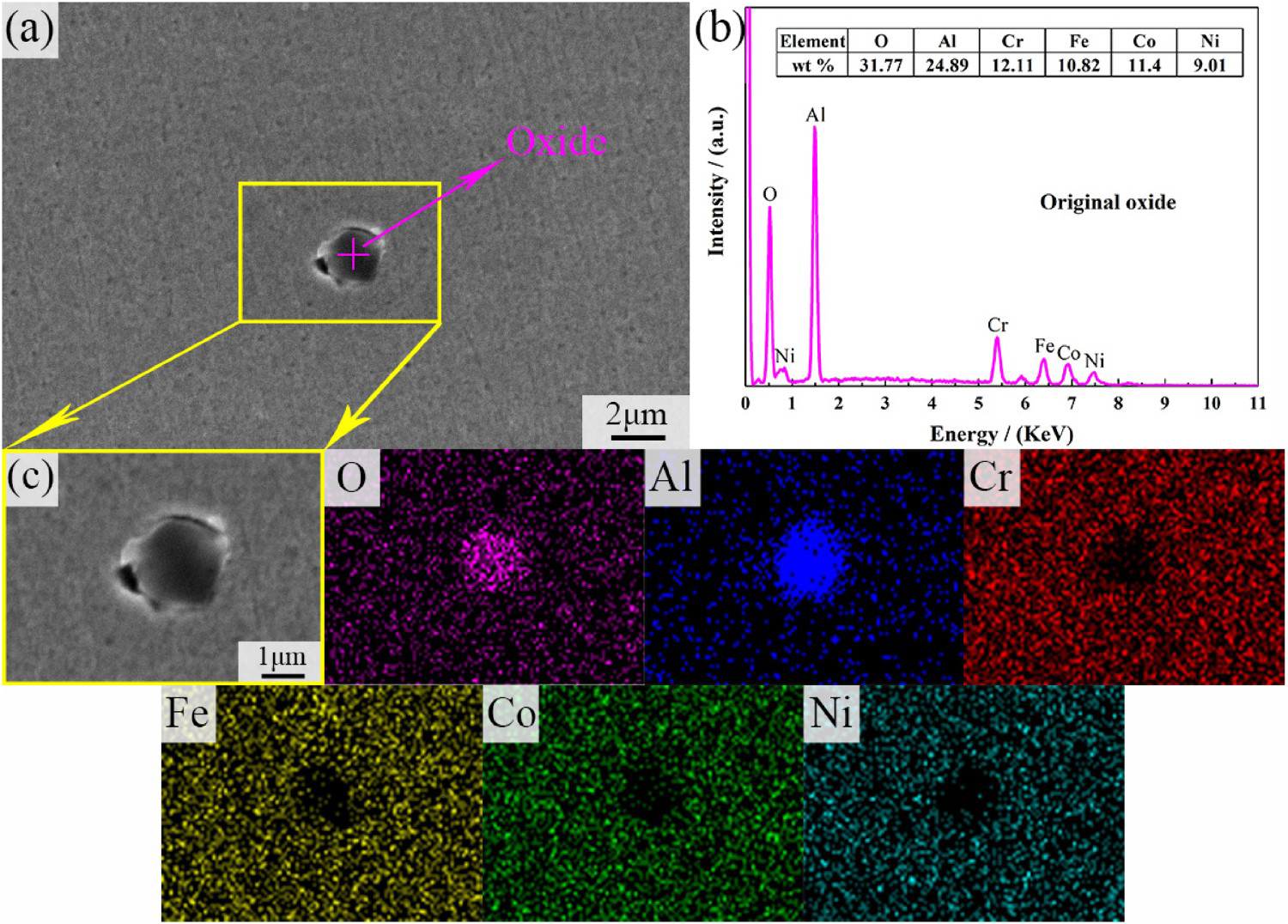
Figure 1 displays the SEM morphology of CoCrFeNi HEA after etching by aqua regia. The alloy exhibits a single-phase FCC structure, which avoids the micro-galvanic corrosion effect between different phases [26,27]. Moreover, some fine gray-white particles are sporadically distributed on the alloy surface, considered inclusions. Among them, in the process of metallographic preparation, a part of the inclusions are dislodged from the matrix due to mechanical polishing, and pores are left behind [28]. The morphology and EDS results of the inclusion at high magnification are given in Figure 2. Based on EDS analysis, the inclusion contains higher contents of O, Al and lower contents of alloy elements (i.e. Cr, Fe, Co and Ni) compared to the matrix, and the corresponding EDS mapping confirms this in Figure 2(c). Also, it can be observed that the inclusion is approximately spherical and surrounded by a hole and micro-gap in Figure 2(a,c). As widely believed, the inclusion enriched in Al and O is brittle and hard, whose thermal expansion coefficient is different from the alloy matrix, which is prone to lattice distortion nearby the inclusion [29,30]. Consequently, micro-gaps and holes are easily formed at the interface between the inclusion and the HEA. Numerous studies have reported the effect of inclusions within microstructure on corrosion resistance [31,32]. Villavicencio et al [33] investigated that alumina inclusions had little effect on the overall corrosion rate but promoted the sprouting of pitting corrosion.
Microstructure of CoCrFeNi HEA. Original morphology (a) and EDS results (b, c) of oxide in CoCrFeNi HEA.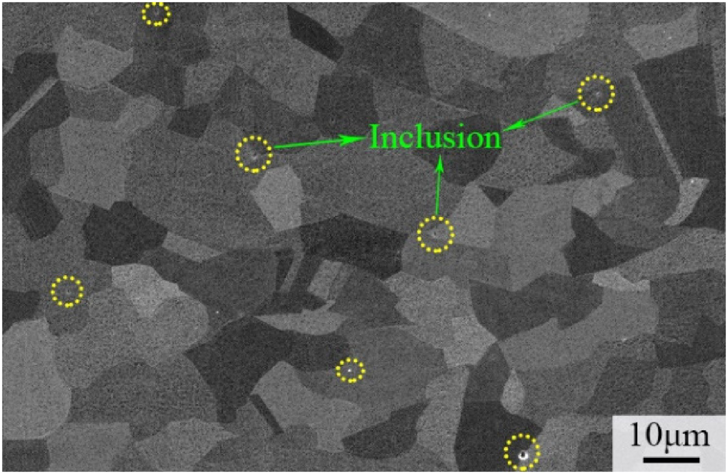
In summary, the single-phase structure of CoCrFeNi HEA avoids the galvanic reaction between different phases and enhances the corrosion resistance, compared to the conventional alloy [27]. The presence of inclusions increases the local corrosion activity. Besides, in the early corrosion development stage, the micro-galvanic corrosion cell is also formed at the oxide/matrix interface, preferentially sprouting pitting corrosion around the oxides, so that the original micro-gaps gradually expand.
Electrochemical measurements
The evolution of the OCP as a function of time can reveal the thermodynamic corrosion trend of the HEA, reflecting the corrosion activity [34]. Figure 3 presents the OCP curves of CoCrFeNi HEA acquired from 3.5 wt.% NaCl solution with different NaHSO3 concentrations over 1800 s. There is no significant fluctuation in the OCP values since the samples are pre-passivated for 1 h before testing. It can be seen that as the NaHSO3 concentration increases, the corresponding OCP value shifts negatively. Therefore, the corrosion tendency of CoCrFeNi HEA enhances with the increase of NaHSO3 concentration.
OCP curves of CoCrFeNi HEA in 3.5 wt.% NaCl solution with different concentrations of NaHSO3.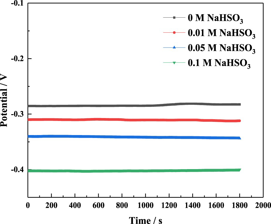
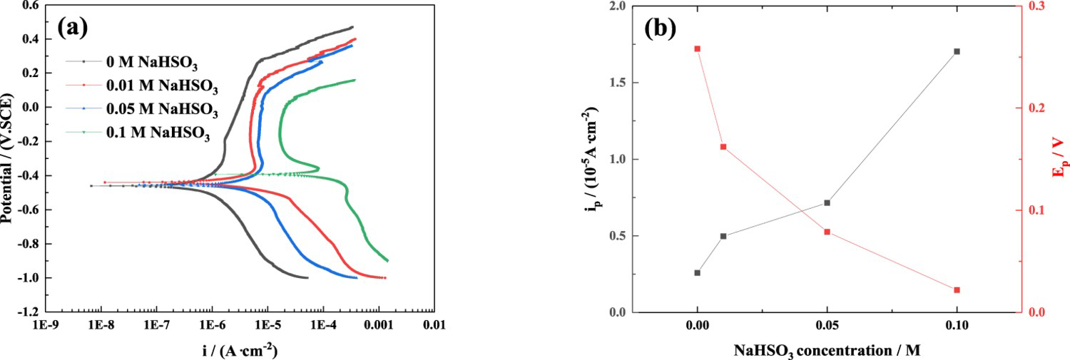
Figure 4(a) exhibits the potentiodynamic polarisation curves of the HEA measured in 3.5 wt.% NaCl solution with various NaHSO3 concentrations. The anodic branches of the curves are roughly similar, forming a typical passivation zone, which indicates that the dissolution and passivation rates of the surface passive film are in a dynamic balance state. On the other hand, the characteristics of the plots are significantly affected by the change in NaHSO3 concentration. The passivation region gradually shifts to the right and becomes narrow with increasing NaHSO3 concentration, so that the passivation current density (ip) also gradually increases. In addition, the relevant electrochemical characteristic parameters are listed in Table 1. It can be visualised that the smallest ip is observed for the specimen tested at 0 M NaHSO3, indicating that the HEA possesses the lowest dissolution rate of the film and the best corrosion resistance. Moreover, the sample displays stable passivation without NaHSO3, while it appears an active–passive transition phenomenon with the addition of NaHSO3, especially in 0.1 M NaHSO3. Thus, the critical passive current density (ipp) increases with the increase of NaHSO3 concentration, indicating that Potentiodynamic polarisation curves (a), ip and Ep values (b) of the HEA in 3.5 wt.% NaCl solution with different concentrations of NaHSO3. The fitted results for potentiodynamic polarisation curves of CoCrFeNi HEA in 3.5 wt.% NaCl solution with different concentrations of NaHSO3. may hinder the passivation of the HEA [35]. As shown in Figure 4(b), the ip value gradually increases with the increasing NaHSO3 concentration, indicating that the corrosion resistance gradually becomes worse, while the pitting potential (Ep) has exactly the opposite change pattern. These results indicate that the sensitivity to pitting corrosion increases.
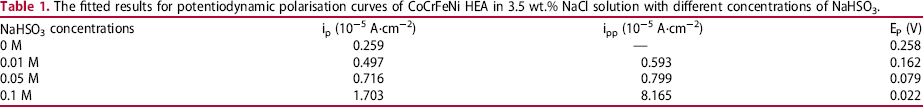
The Nyquist and Bode plots of the HEA measured with various NaHSO3 concentrations are presented in Figure 5. The Nyquist curves with incomplete capacitive impedance arcs are in Figure 5(a). These curves progressively decrease in radii with increasing NaHSO3 concentration, and the corresponding corrosion resistance becomes weaker [36]. The value of impedance modulus at 0.01 Hz in the Bode plot also reflects the change in the anti-corrosion property of the HEA [37]. In Figure 5(b), the |Z| value is maximum at 0.01 Hz in NaCl solution with 0 M NaHSO3, which reveals the strongest corrosion resistance, while the |Z| value is minimum in 0.1 M NaHSO3 solution. Also, it can be seen from Figure 5(c) that the maximum phase angles of the samples in different concentrations are between 70° and 80°, suggesting that a uniform and stable passivating film is formed on the samples [38], which is conducive to the formation of a barrier to prevent the penetration of corrosive ions.
EIS curves of the HEA at the film formation potential of 0 VSCE in 3.5 wt.% NaCl solution with different concentrations of NaHSO3: (a) Nyquist plots; (b, c) Bode plots.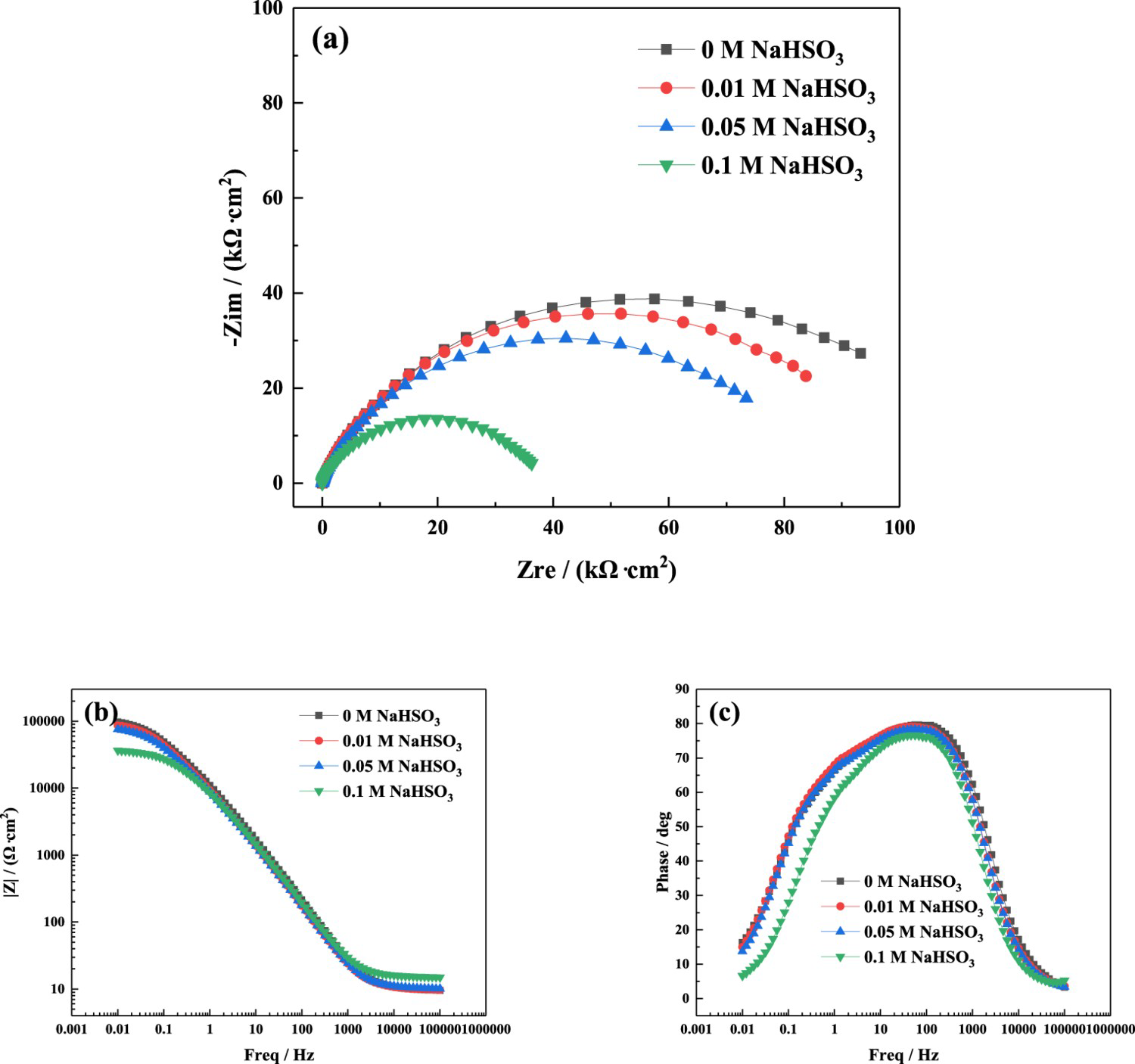
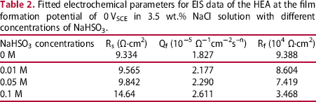
To determine the electrochemical parameters reflected by the impedance spectrum, the EIS curves for different conditions are fitted using the equivalent circuit model shown in Figure 6. Table 2 displays the relevant characteristic parameters: Rs represents the solution resistance, Rf is the resistance of the passive film covering the HEA, and Qf as the film capacitance reflects the denseness and porosity of the film, respectively. The results demonstrate that the Rf value decreases with the increase of NaHSO3 concentration, which implies that the protective performance of the film is weakened. In addition, the Qf value increases with increasing NaHSO3 concentration, indicating that the film is less dense and more porous, increasing the risk of ion reaction with the HEA matrix.
Equivalent circuit model used for fitting EIS data. Fitted electrochemical parameters for EIS data of the HEA at the film formation potential of 0 VSCE in 3.5 wt.% NaCl solution with different concentrations of NaHSO3.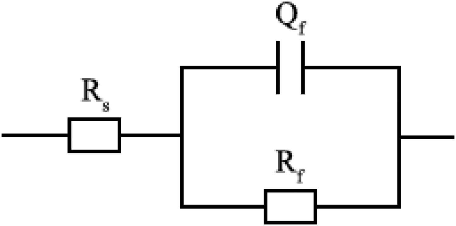
Numerous studies have shown that the semiconductor properties of the passivating film formed on the alloy surface are highly correlated with corrosion behaviour [39,40]. The Mott–Schottky theory is widely applied to study the semiconductor behaviour of the film [41]. Based on the theory, the semiconductor behaviour and carrier density of the film formed on CoCrFeNi HEA in 3.5 wt.% NaCl solution with different NaHSO3 concentrations are investigated. The space charge layer capacitance followed by external electrode potential is calculated by the following Equation (1).
Mott–Schottky plots (a), carrier densities and thickness (b) of the passive films formed on the HEA at the film formation potential of 0 VSCE in 3.5 wt.% NaCl solution with different concentrations of NaHSO3.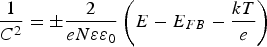

 concentrations on the passivation film, the following Equation (3) is adopted to calculate the film thickness [43].
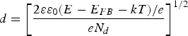
 concentration, the protection performance gradually drops. And when the HEA specimen is in the concentration of 0.1 M NaHSO3, the defects within the film are the most abundant and the corrosion resistance of the HEA is the worst.
Furthermore, the blue curve in Figure 7(b) depicts the thickness of the passivation films on the HEA surface in 3.5 wt.% NaCl solution with different  concentrations. The thicker the film is, the better its protection is. Therefore, in the 0 M NaHSO3 solution, the film is the thickest and its protective performance is the best. The results of the Mott–Schottky curve are consistent with those of the EIS tests, and the pattern of carrier density is in accord with that of Qf value above in Table 2.
AC interference analysis
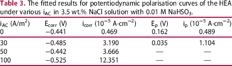
Figure 8 displays potentiodynamic polarisation curves and fitted corrosion current density (icorr) values of CoCrFeNi HEA in 3.5 wt.% NaCl solution with 0.01 M NaHSO3 under different iAC. It can be observed that the shapes of polarisation curves measured at 0 and 30 A/m2 are similar and both show apparent passivation region, which indicates the formation of a passivating film on the HEA surface. However, the curves tested at 50 and 100 A/m2 present the obvious activation behaviour. Comparing the fitted icorr values for polarisation curves exhibited in Figure 8(b) and Table 3 demonstrates that the increase in NaHSO3 concentration significantly enhances the occurrence of corrosion, especially at high iAC of 50 and 100 A/m2. This may be due to the fact that more H+ ions are generated with an increased hydrogen evolution reaction under AC application [25], which promotes the corrosion reaction rate. Moreover, when the iAC increases from 0 A/m2 to 100 A/m2, the corrosion potential (Ecorr) generally tends negative shift, indicating a gradual increase in corrosion tendency. As listed in Table 3, the HEA without AC has a lower passive current density (ip) and nobler pitting potential (Ep), compared with those tested at 30 A/m2, revealing that the passivity of the HEA is dropped even at a low iAC of 30 A/m2, that is, the formation of pits is facilitated.
Potentiodynamic polarisation curves (a), icorr values (b) of the HEA interfered at different iAC in 3.5 wt.% NaCl solution with 0.01 M NaHSO3. The fitted results for potentiodynamic polarisation curves of the HEA under various iAC in 3.5 wt.% NaCl solution with 0.01 M NaHSO3.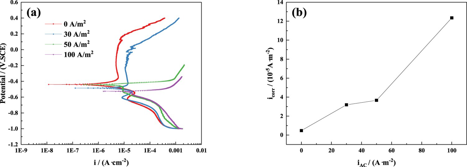
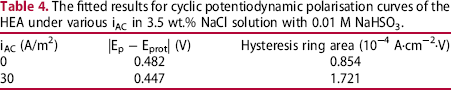
The development process of pitting is generally as follows: pitting initiation, metastable pitting growth and stable pitting formation. Generally, Ep reflects the generation of stable pitting, and the potentials of pitting initiation and metastable pitting development are usually between Ep and Eprot [45,46]. Figure 9(a) compares the cyclic polarisation curves of CoCrFeNi HEA with or without AC in 3.5 wt.% NaCl solution containing 0.01 M NaHSO3. Several current peaks between Ep and Eprot can also be observed, which implies the production of metastable pitting [47]. Moreover, as shown in Figure 9(b), the value of |Ep−Eprot| at 0 A/m2 is close to that at 30 A/m2, while the hysteresis loop area at 30 A/m2 is much larger than that at 0 A/m2. Table 4 lists the specific values of the above two index data. As known to all, the hysteresis loop area can be used to evaluate the resistance to pitting corrosion of metals, i.e. the smaller the hysteresis loop area, the less susceptible to pitting corrosion [48]. Thus, the imposed AC weakens the pitting resistance of the HEA.
Cyclic potentiodynamic polarisation curves (a), the values of |Epit − Eprot| and hysteresis ring area (b) of the HEA at different iAC. The fitted results for cyclic potentiodynamic polarisation curves of the HEA under various iAC in 3.5 wt.% NaCl solution with 0.01 M NaHSO3.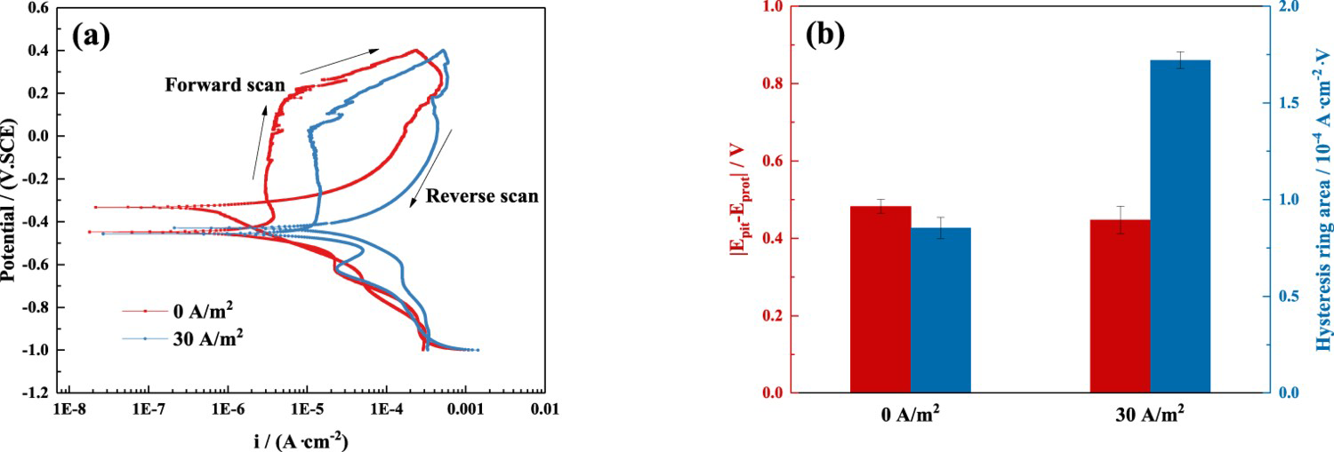
To further investigate the effect of different applied iAC on the formation and development process of metastable pitting, various low iAC (0, 3, 5 and 10 A/m2) are selected and applied to the HEA electrode. The influence of AC interference on the pitting process of the HEA is statistically analysed by the potentiostatic polarisation test.
Metastable pitting analysis
Figure 10 depicts the current–time transient curves obtained for CoCrFeNi HEA under different iAC in 3.5 wt.% NaCl solution with 0.01 M NaHSO3. Clearly, the number and amplitude of the current density peaks increase with increasing iAC, which demonstrates that AC promotes the development degree of metastable pitting corrosion. Since the applied AC generates more active sites on the HEA surface, resulting in high pitting sensitivity. Zhu et al. [24] reported that a large number of H atoms produced by imposed AC accumulate at the weak position and defects within the passivating film, promoting pitting nucleation. To quantitatively analyse the effect of AC interference on metastable pitting behaviour, the statistical method was adopted. The background current density (ibg) in Figure 10 is determined to be 1.2 nA/cm2 by potentiostatic polarisation test of CoCrFeNi HEA tested in Na2SO4 solution. When the peak value of the current transient (ipeak value) is greater than the ibg, the peak is counted. Besides, for overlapping current density peaks, the current densities of adjacent two peaks differ by less than 50%, which can be viewed as the same metastable pitting peak, as shown in Figure 12 (b).
Current-time transient curves of CoCrFeNi HEA at different iAC in 3.5 wt.% NaCl solution with 0.01 M NaHSO3.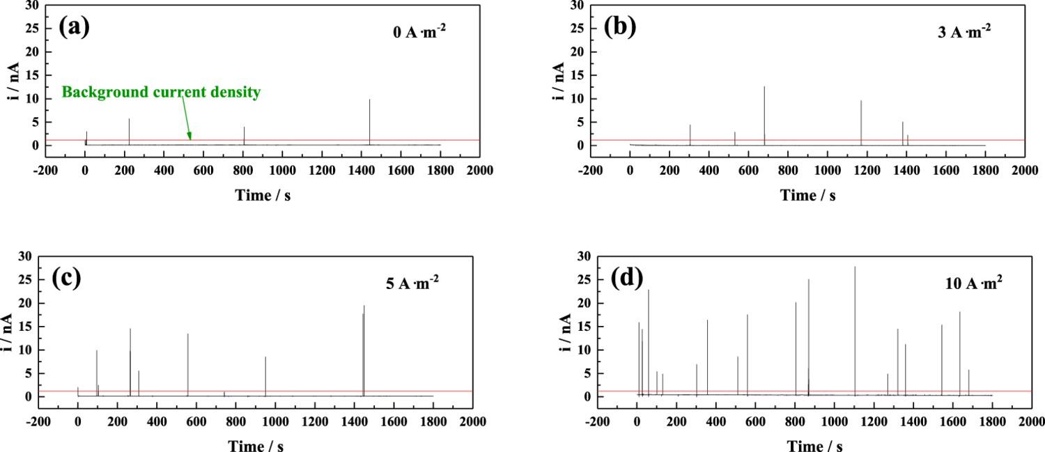
Figure 11(a) exhibits the variation trend of the average pitting number density (Navg), and average ipeak value of metastable pitting on the HEA at different iAC in 3.5 wt.% NaCl solution with 0.01 M NaHSO3. The values of Navg and average ipeak value increase significantly with the increase of applied iAC. This indicates that the metastable pitting is easily excited to nucleation as iAC rises. Figure 11(b) displays the average and maximum lifetime of the metastable pit at different iAC, reflecting the growth and repassivation rates of metastable pitting. It can be seen that the average and maximum lifetime become longer with increasing iAC. The application of AC extends the life of metastable pitting, stimulates its full nucleation and growth, and inhibits the repassivation process. Therefore, metastable pitting is easier to evolve into stable pitting, which is difficult to repair from repassivation. The related literatures [49,50] indicate that AC promotes the migration and ionisation of ions. As a result, metastable pitting gradually expands to stable pitting as metal elements dissolve.
Average pit number density, average peak value of current transient (a), lifetime of metastable pit (b) on CoCrFeNi HEA at different iAC.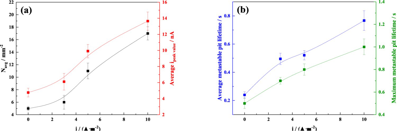
Figure 12 presents the single peak transient and overlapped peaks transient of the metastable pitting. The current peak in Figure 12(a) goes through three stages of development: increases slowly, rises rapidly and decreases sharply, which corresponds to the initiation, growth propagation and repassivation of the metastable pitting [51]. Where ipeak represents the peak current density; tgrow and trep are the growth time and repassivation time of metastable pitting, and tLifetime denotes the whole development process of metastable pitting. The overlapping peak transient is shown in Figure 12(b), which can be explained by the fact that metastable pitting occurs when structural defects exist in the vicinity of the pitting, leading to multiple pitting nucleations [52]. On the other hand, metastable pitting is an unstable process, causing overlapping peaks and current fluctuations.
Single peak transient (a) and overlapped peaks transient (b) of metastable pitting of the HEA.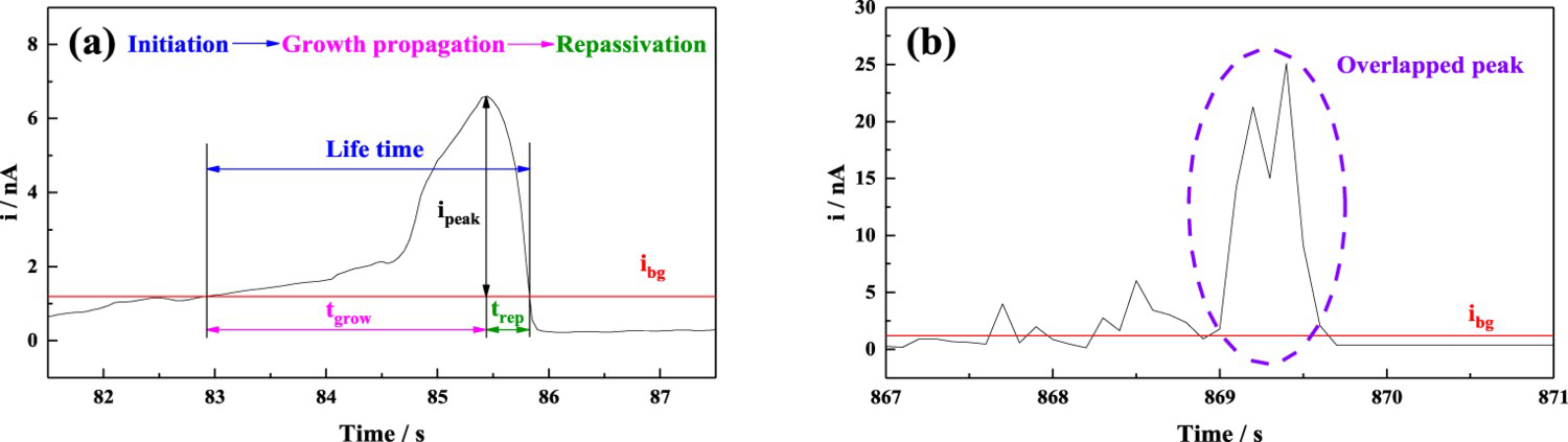
Immersion test
Figure 13 shows the average corrosion rate of CoCrFeNi HEA in 3.5 wt.% NaCl solution with different NaHSO3 concentrations. The corrosion rate of the HEA rapidly increases with increasing NaHSO3 concentration. Combined with the above analysis results, it can be concluded that the corrosion resistance of the HEA is weakened with the increase of NaHSO3 concentration. The corrosion morphologies of the HEA immersed in NaCl solution with different concentrations of NaHSO3 for 8 d are exhibited in Figure 14. It can be observed that the number of pits produced on the HEA surface increases with an improved NaHSO3 concentration. For 0.1 M NaHSO3, some pits fuse and expand in the local region of the matrix. Therefore, the corrosion characteristics also confirm that the presence of The average corrosion rates of CoCrFeNi HEA in 3.5 wt.% NaCl solution with different concentrations of NaHSO3. Corrosion morphologies of the HEA immersed in 3.5 wt.% NaCl solution with different concentrations of NaHSO3 for 8 d: (a,b) 0 M, (c,d) 0.05 M, (e,f) 0.1 M. reduces the anti-corrosion performance of the HEA.
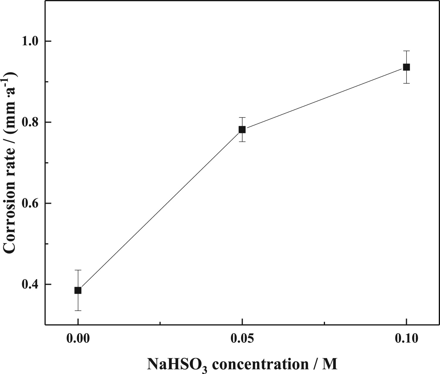
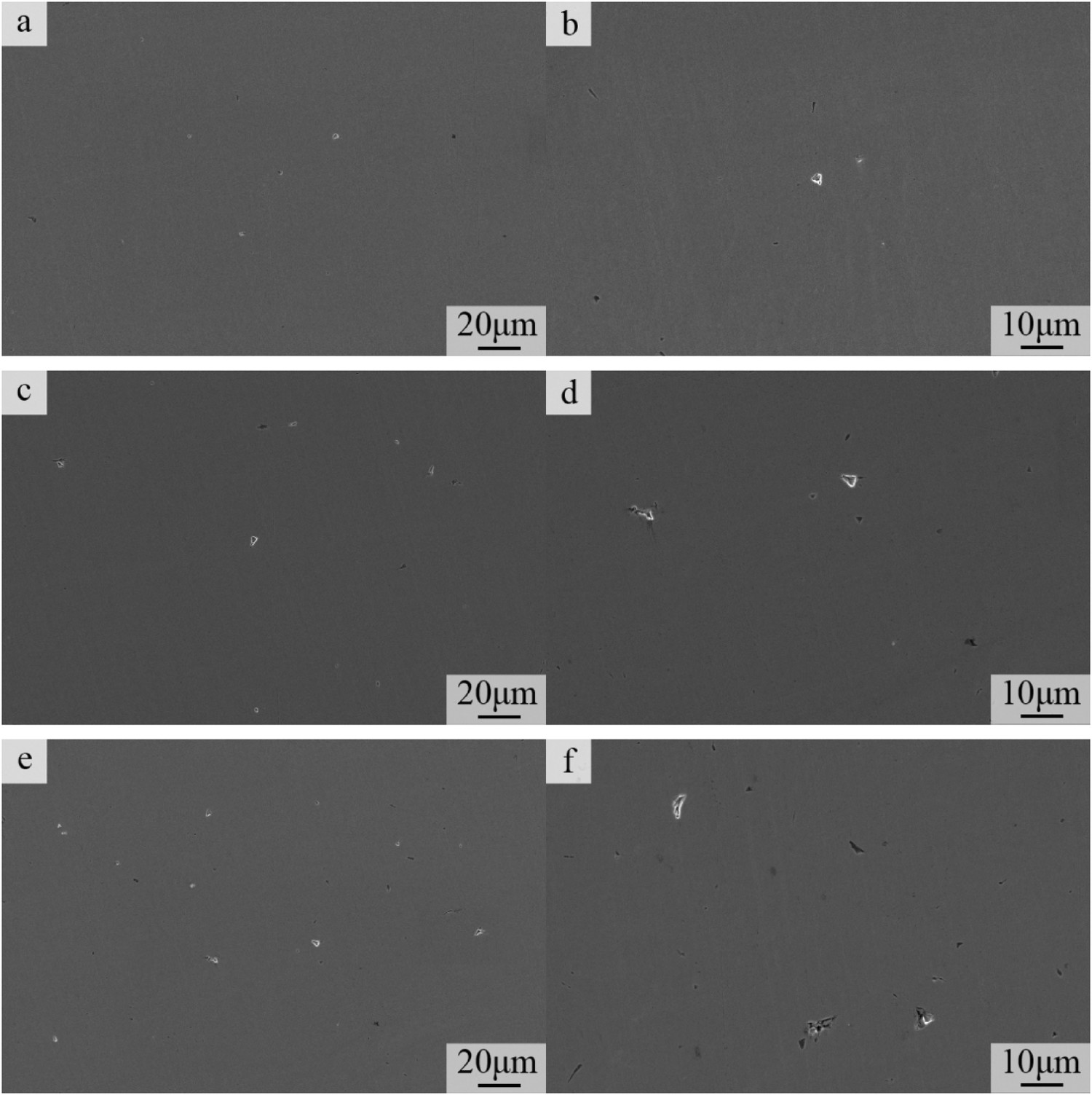
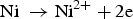
Figure 15 depicts the morphologies and EDS results of pitting on the HEA immersed in 3.5 wt.% NaCl solution with 0.1 M NaHSO3 for 8 d. Through the semiquantitative analysis result (Figure 15b), it can be found that the content of Ni element inside the pitting is significantly reduced compared with the matrix, and the percentage of Fe element is almost unchanged, whereas the contents of Cr and Co increase, which reveals that the occurrence of pitting may be induced by the selective dissolution of Ni element. The mapping result in Figure 15(c) also further proves this. The dissolution behaviour can also reduce the compactness and stability of the passive film covering the HEA, and its protection will be weakened.
Morphologies and EDS results of pits on the HEA immersed in 3.5 wt.% NaCl solution with 0.1 M NaHSO3 for 8 d.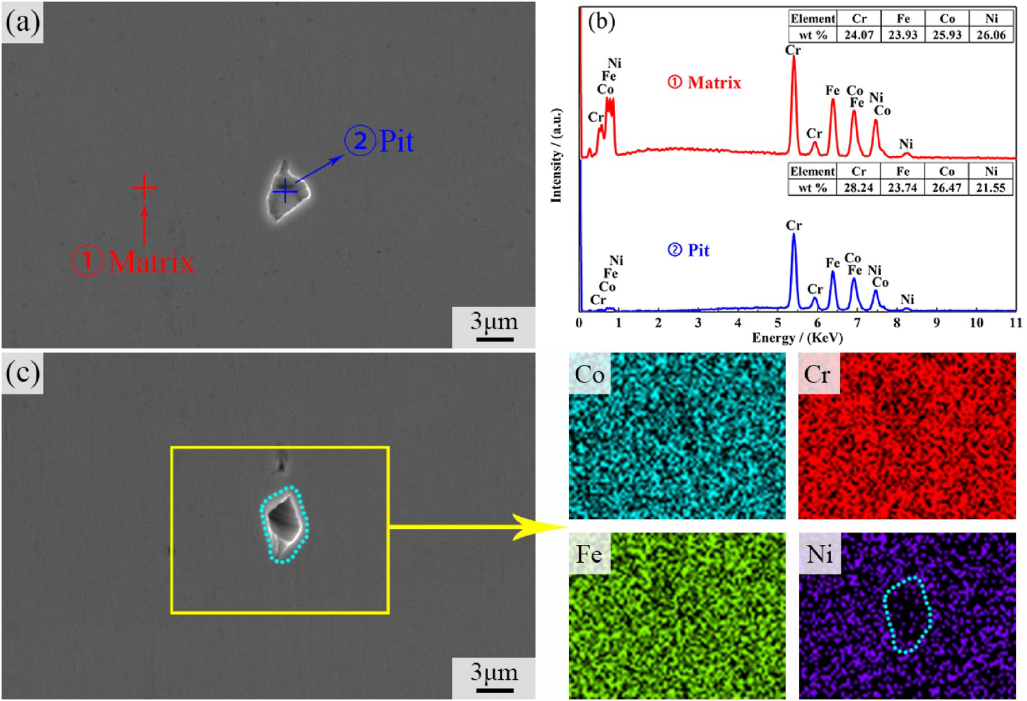
Moreover, the composition of dissolved oxide inclusion after the immersion test is detected in Figure 16. Compared with the original oxide inclusion in Figure 2, the contents of Cr, Fe, Co and Ni elements markedly decrease. Obviously, pitting occurs at its surrounding oxide, which may be caused by the effect of micro-galvanic corrosion cell formed between oxide and matrix. This phenomenon also exists in our previous study [53], which is detrimental to the corrosion resistance of the alloy.
EDS results of oxide inclusion within the HEA immersed in 3.5 wt.% NaCl solution with 0.1 M NaHSO3 for 8 d.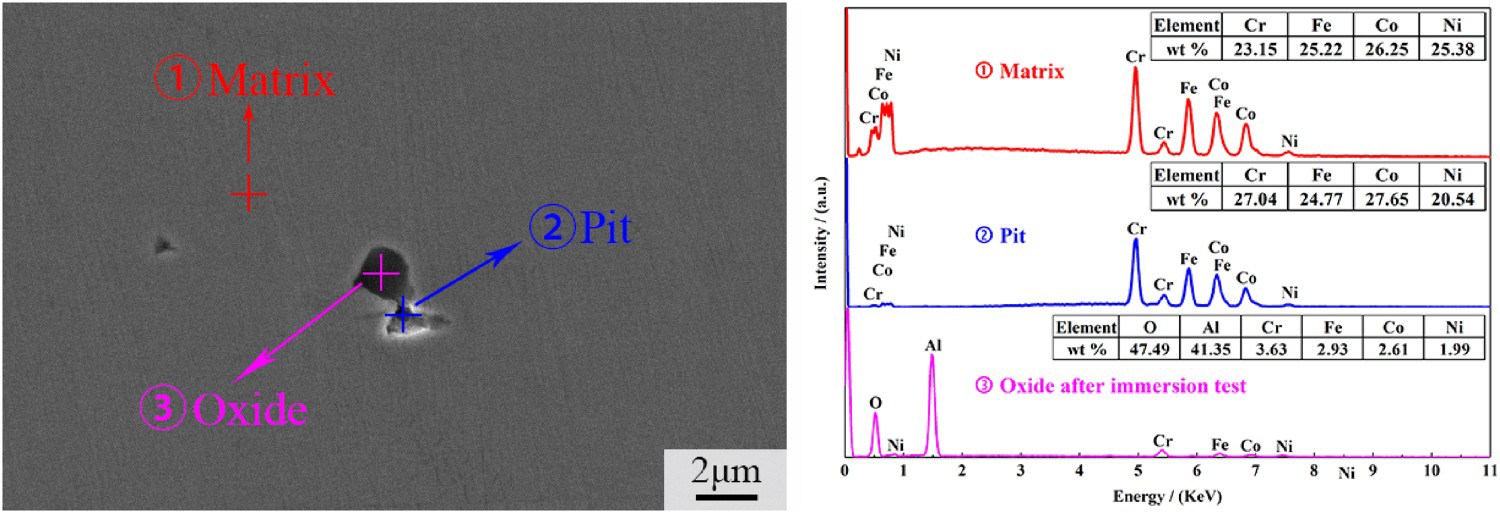
Corrosion mechanism
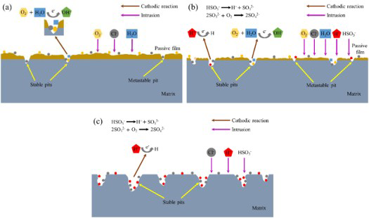
According to all the above-mentioned results, the corrosion mechanism of CoCrFeNi HEA under different conditions is shown in Figure 17. A large number of studies have reported that Cl− has a significant negative effect on the corrosion sensitivity of alloys in NaCl environment [54 56]. As displayed in Figure 17(a), the corrosion of HEA is mainly affected by Cl− in 3.5 wt.% NaCl solution and the main cathode reaction is the oxygen reduction reaction (Reaction 4). During the corrosion process, Cl− ions are adsorbed on the active sites and defects of the passivating film, promoting the anodic dissolution (Reaction 5), which is the main reason for the pitting initiation on the HEA surface [11].
Corrosion mechanism diagram of the HEA under different conditions (a) in 3.5 wt.% NaCl solution, (b) in 3.5 wt.% NaCl solution with NaHSO3, (c) interfered by AC in 3.5 wt.% NaCl solution with NaHSO3.
 (Figure 17(b)), the thickness of the passive film thins and its integrity becomes worse, compared with that without the addition of
  . Moreover, the cathodic reaction is an oxygen-consumption reaction in the initial corrosion stage. The presence of
  has a certain effect on the cathode reaction process [57]. With the ionisation of
  (Reaction 6), a large amount of H+ enters the solution system, increasing H+ concentration in the local region of the bulk solution. That is, hydrogen evolution may occur as part of cathode reactions (Reaction 7). Thus, many H atoms penetrate into the defect sites within the passive film, which increases film instability [58]. Therefore, more pits are produced as NaHSO3 concentration increases. It is well known that SO3 2- is unstable in solution and tends to oxidise (Reactions 8), leading to the formation of FeSO4 (Reaction 9). Where Fe2+ comes from the chemical dissolution of oxides presented in Figure 16. The FeSO4 continuously oxidises and forms H2SO4 through the cyclic acidification mechanism (Reactions 10,11) [59], resulting in further acidification of the solution. Therefore, SO4 2- plays a catalytic role in the reaction process, accelerating the corrosion of the HEA. In addition, Cl− ion increases the conductivity of the matrix/solution interface and promotes the electrochemical reaction. Hence, the combined effect of Cl− and
  promotes the anodic dissolution of the HEA (Figure 13).


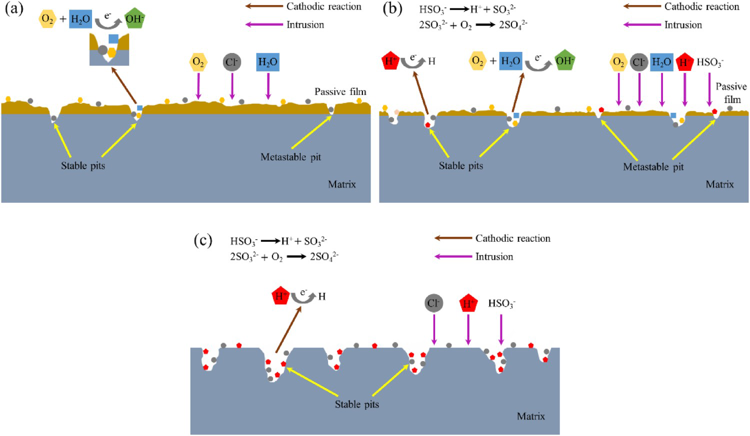
As expressed in Figure 17(c), the hydrogen evolution reaction (Reaction. 7) is the dominant cathode reaction due to the influence of an external AC. The role of the applied AC is generally reflected in two aspects [22]. On the one hand, in the positive half cycle of AC, the electrolysis of water is motivated (Reaction. 12), and the continuous production of oxygen accelerates the oxidation process of SO3 2- and the cyclic acidification, thus generating a large amount of H+. Additionally, under AC application, with the increase in the migration rate [60] and adsorption [25,61] of ions, the reaction between harmful ions and oxides/hydroxides in the passivating film is intensified, which makes the corrosion of the HEA more serious and even difficult to form a passive film. On the other hand, in the negative half cycle of AC, the hydrogen evolution reaction is accelerated (Reaction. 13) [60]. Hydrogen ions produced by electrolysis of water and ionisation of  participate in the cathodic reaction process, thus stably generating hydrogen atoms. Some parts of H atoms combine together to form H2, as confirmed by bubbles on the counter electrode surface. The produced H2 diminishes the bonding force between the passivated film and the matrix, inducing a certain internal pressure. As a result, the defects within the film increase, and its thickness thins, which facilitates the rupture of the film [25,62,63].


Conclusions
The corrosion behaviour and mechanism of CoCrFeNi HEA with imposed AC in a simulated marine environment containing different concentrations of NaHSO3 were systematically investigated, and the main conclusions were as below:
With the increase of NaHSO3 concentration, the passivation region became narrow, and the ip value increased, suggesting that the corrosion of the HEA was facilitated. In 0.1 M NaHSO3 solution, the polarisation curve exhibited a visible transition zone, indicating that the increase in NaHSO3 concentration decreased the passivity of the HEA. As the concentration of NaHSO3 increased, the defect densities within the passivation film increased and its protection performance became weaker, thus diminishing the anti-corrosion property of the HEA. Moreover, the corrosion rate of the HEA in NaCl solution with 0.1 M NaHSO3 was about 2.4 times that without the addition of NaHSO3. Due to the influence of an external AC, the corrosion behaviour of the HEA was evolved from passivation characteristic at low iAC to active state at high iAC. In addition, the application of AC prolonged the life of metastable pitting, stimulated its full nucleation and growth, and inhibited the repassivation process. With the increase of iAC, the Navg value significantly increased from 5 to 17 mm−2. The formation of pitting on the HEA surface was related to the selective dissolution of Ni element. And the selective dissolution of Cr, Fe, Co and Ni elements occurred inside the oxide inclusion.
Footnotes
Disclosure statement
No potential conflict of interest was reported by the author(s).