
Abstract
Quasi-static multilayer piezoelectric actuators are finding more and more applications, for example, in the field of aerospace; however, their properties are still not fully characterised, in particular at a high temperature. The present study targets the full characterisation of both soft-doped and hard-doped lead zirconate titanate (PZT) up to 200°C. A simple set of tests and test results are presented, focusing particularly on dielectric losses and creep effect. Dielectric losses were found to decrease with the increasing field for soft-doped PZT, while they tend to increase for hard-doped PZT. The interpretation is that soft-doped PZT has less hysteresis at high field. The creep behaviour is also significantly different. While soft-doped PZT follows a logarithmic model with low and stable creep rates, hard-doped PZT exhibits non-logarithmic creep with increasing or decreasing rates depending on the temperature. This behaviour is attributed to the generation of additional poling in the material.
Introduction
Over the years, quasi-static piezoelectric actuators, in particular multilayer actuators, have gained maturity, finding numerous applications, for example, in aerospace applications. However, although some literature is available on large signal stress-strain behaviour,1-4 in many cases, the designer still misses essential parameters for describing the behaviour of these actuators, in particular for high-temperature applications. The present work is performed within the project AeroPZT, specifically funded under the Clean Sky Joint Technology Initiative (EU FP7). The project partners, Plant Integrity Ltd (UK), Cedrat Technologies (France), Noliac (Denmark) and Politecnico di Torino (Italy), are targeting the development of materials and processes for the application of piezoelectric materials in aero engine controls, which implies harsh environmental conditions, particularly elevated temperature. Applications of such actuators could include valve control for fuel staging or clearance control. For such non-resonant applications that require high strain and optimised mass, multilayer piezoelectric actuators are well adapted. For these actuators, the material parameters deviate significantly from catalogue values due to the high field, hence the need for specific characterisation.
The target of the present work is to provide a set of curves (allowable reverse field, apparent capacitance, apparent losses, free stroke, blocking force and height according to the temperature) for two different materials, one hard-doped and one soft-doped lead zirconate titanate (PZT) ceramic, leading to a complete characterisation of the actuator. The hard-doped PZT is based on Noliac's NCE46 while the soft-doped PZT is using NCE51. The samples used for this characterisation are either single multilayer elements (10×10×2 mm3) or small stacks of multilayer elements (5×5×14 mm3), rated for low voltage (between 100 and 200 V at a nominal field of 3 kV mm−1). Except for the measurement of coercive field, all samples were poled using standard parameters (application of 2–3 kV mm−1 at 130–150°C for several minutes).
Test data are valuable to designers who have to ensure functionality over a wide temperature range and provide more accurate results than small signal characterisation.
The present paper describes a relatively simple method for the complete characterisation of low-loss PZT actuators at an elevated temperature, providing the designer with the data required for a fast and effective design process. Results on dielectric losses and creep are presented in detail while other results will be presented in further publications.
Experiment design
It would be tempting to design an experimental set-up capable of measuring all parameters in a single experiment. However, the very specific equipment needed for the characterisation makes the integration difficult; therefore, a multi-experiment approach was adopted.
In the first series of test, the coercive field can be measured on unpoled samples. This is achieved by applying a low-frequency sinusoidal signal of increasing amplitude while monitoring charge through a Sawyer-Tower circuit.
Large signal capacitance and losses can be measured in a second stage. The procedure for this measurement is described in detail in the following paragraph.
Coefficient of thermal expansion (CTE), free stroke and creep rate can be measured in the same experiment, driving the actuator with a trapezoidal signal. The procedure for this measurement is also detailed below.
Finally, stiffness (for the evaluation of blocking force) is the most difficult parameter to evaluate as it requires simultaneous force and displacement measurement. In the frame of this study, a concession was made that stiffness would only be evaluated for small signal through the analysis of frequency constants; however, methods reported in the literature 5 could also be applied.
Only the procedures for the measurement of dielectric losses and creep are described in detail below, as these two parameters are the main focus of the present publication.
Dielectric losses
Dielectric losses are measured in the same experiment as capacitance. The sample under test is submitted to a unipolar 1 kHz sine voltage. This frequency was selected in order to obtain results comparable to standard measurements according to EN50324. The effect of frequency on dielectric properties is not considered in this study; however, the mechanisms seem to be well understood,6,7 so the effects of frequency could be included.
The excitation voltage is generated by a signal generator (Agilent 33250A) coupled to a high-power (300 V, 10 A peak) amplifier (Noliac NDR6880) as depicted in Fig. 1. In order to obtain data for different levels of excitation, the signal generator is programmed to generate sinewaves of increasing amplitude. For each amplitude, 20 sinewaves are applied, allowing a good averaging. The duration of each measurement is 0.2 s, which is short in comparison to the thermal inertia of the sample. Therefore, the influence of self-heating is minimised.
Schematic of the test arrangement for the measurement of large signal capacitance and dielectric losses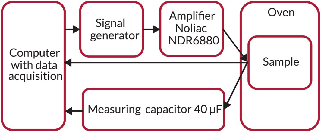
The dielectric charge absorbed by the sample is measured through a simple Sawyer-Tower circuit including a capacitor significantly larger than the sample under test (factor 20).
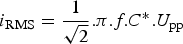
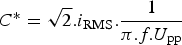
Using a computer with data acquisition, both voltage across the sample and dielectric charge can be monitored simultaneously. The usual equations for current [equation (1)] and dielectric losses [equation (2)] can be re-arranged to express large signal capacitance C* and dielectric losses tan δ* as a function of measured parameters. The large signal capacitance (or apparent capacitance) is calculated from equation (3). It should be noted that due to the non-linear behaviour of the PZT, peak current can be different from √2 times the root mean square (RMS) current.
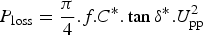
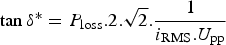
The large signal dielectric loss factor (or apparent loss factor) is then calculated from equation (4).
This test method is adapted to automated post-processing and provides for each measurement a set of data points between 0.3 and 3 kV mm−1 peak field in unipolar driving conditions, which is in accordance with the recommendations of most suppliers of multilayer piezoelectric actuators.
Creep
Creep is measured in the same experiment as thermal expansion and stroke. Thermal expansion is a very difficult parameter to measure, as it requires the measurement of very small displacements with an extreme stability over time and temperature. For this task, a thermo-mechanical analyser (TMA CX04R, company RMI) was used. This piece of equipment allows measurement at a rate of 4 s. Therefore, it was not possible in our tests to measure stroke in a dynamic way (for example, 1 Hz) as it is usually done. Instead, stroke is measured in quasi-static conditions after application of a positive voltage step.
After a temperature stabilisation time, the sample is submitted to a positive voltage step corresponding to the maximum recommended field of 3 kV mm−1. In order to account for the creep effect, this voltage is maintained for two minutes. The sample is then discharged and allowed to recover the accumulated creep for 5 min. Temperature is subsequently increased to the next step at a rate of 1°C min−1 (Fig. 2). Charge and discharge of the sample are realised through a set of resistors providing a time constant of approximately 0.5 s. This is to avoid noise on the voltage signal that could lead to unwanted movement of the sample.
Timing of the measurement performed for each temperature test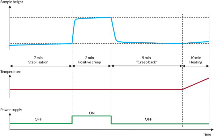
This measurement method was selected because it can provide several parameters such as free displacement, creep and CTE using readily available resources.
Test results
The study provided significant amounts of test results. In the present paper, we chose to focus on the evolution of dielectric losses and of the creep effect.
Dielectric losses
The loss mechanisms in PZT have been largely studied. However, most studies focus on transducer applications operating at resonance. 8
As reported in the literature,
6
apparent dielectric losses increase significantly for a large signal. This was confirmed in our measurements as can be seen in Fig. 3.
Apparent dielectric loss factor for a soft-doped and b hard-doped multilayer PZT actuators at given temperatures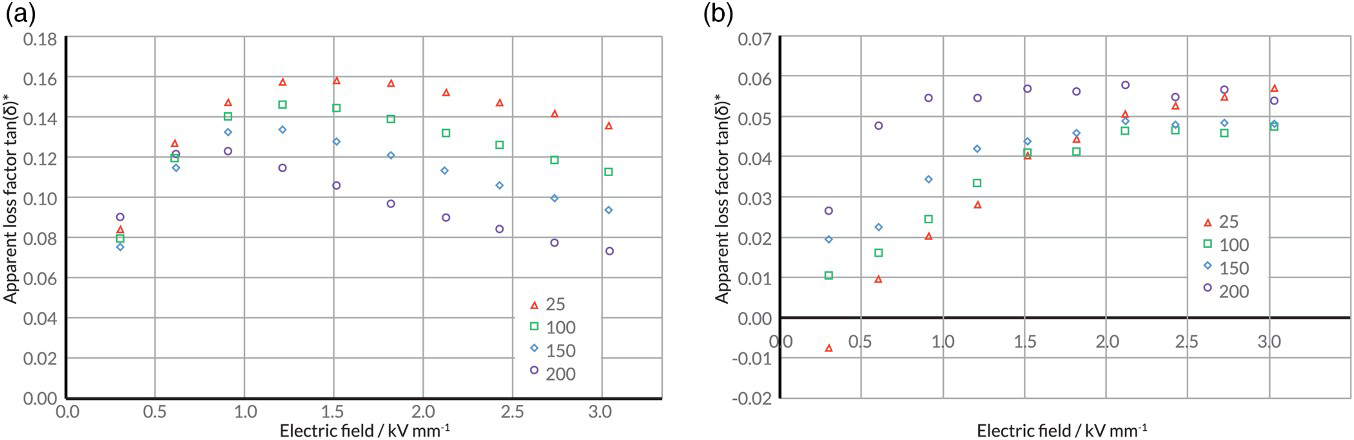
For soft-doped PZT, after the initial increase, dielectric losses tend to level and decrease above a certain field. This effect can be related to the shape of the hysteresis curve. For soft-doped ceramics, the P-E curve tends to become thinner at high field, with a point of maximum hysteresis around 1 kV mm−1. When generating incursions of increasing field amplitude, the area within the P-E curve tends to increase more slowly at a very high field, leading to a relative decrease in the losses. In other words, for soft-doped PZT, the hysteretic losses appear to saturate above a certain level.
This saturation threshold changes with the temperature. At elevated temperature, the dielectric losses decrease overall. The point of maximum losses occurs at a lower field.
Figure 4 depicts dielectric charge Q versus electric field at three different peak fields and for two temperatures: 25 and 200°C. In order to be able to compare the curves, the dielectric charge (Q) is divided by the apparent capacitance (C*). For soft-doped PZT (Fig. 4a), while the curves at low field are very similar, it is clear that, at higher field, the P-E curve measured at 200°C presents a narrower hysteresis loop than that measured at 25°C. In addition, the curves tend to be more elongated at a high field, highlighting the levelling of hysteretic losses.
Comparison of normalised P-E curves for a soft-doped and b hard-doped multilayer PZT actuators at 25 and 200°C for different peak electric fields Curves are offset for legibility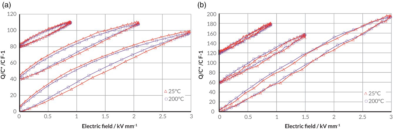
On the other hand, for hard-doped PZT, the decrease in dielectric losses at a high field was not observed. At room temperature, the apparent loss factor follows an increasing trend. As temperature increases, the curve seems to shift to the left, so losses reach a maximum at lower field and maintain this value up to the maximum tested field of 3 kV mm−1.
As illustrated in Fig. 4b, for hard-doped PZT, the shape of the P-E loops is very similar at 25 and 200°C, particularly at a high field. At a low field, P-E hysteresis at room temperature is slightly lower than that at 200°C. In addition and contrary to soft-doped ceramics, the elongation of the curves at a high field cannot be observed, supporting the fact that hysteretic losses do not decrease with the field.
Hard-doped PZT is the preferred material family for high-power applications due to its lower dielectric losses. This is in particular true at room temperature, for low-field applications. For high-field applications, hard-doped PZT maintains an advantage. However, the gain in dielectric losses becomes less and less significant as temperature increases. These test results mean that the material choice for high-temperature applications is less clear cut.
Creep effect
The analysis of creep has drawn some attention recently. Many studies focused on creep during the initial poling process.9,10 Although this is interesting from a material development perspective, this is of little interest for end-users who receive pre-poled actuators. Also, in these studies, the effect of temperature is rarely considered.
Traditionally, creep in pre-poled PZT is described by an equation of the type:
11
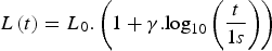
with L(t) the elongation over time, L0 the elongation after 1 s and γ the creep rate. This model has been widely used for model-based creep compensation, 12 although more recent studies indicate that, under constant electric field, the material experiences a poling state change with a non-monotonic creep strain. 13
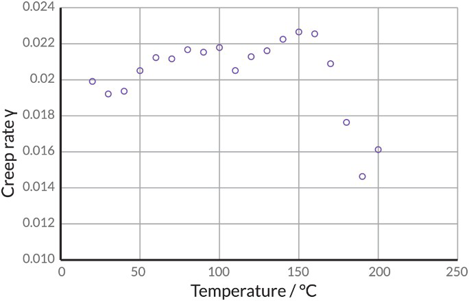
Nevertheless, our measurements on soft-doped PZT are in good accordance with the logarithmic model in the whole temperature range up to 200°C, as can be seen in Fig. 5a, which is a plot of the sample elongation L normalised against its instantaneous elongation L0 versus time on a logarithmic scale. The instantaneous elongation L0 is identified by extrapolation. The creep rate was found to be low and relatively stable, approximately 2.3% per decade, decreasing to 1.4 above 150°C (Fig. 6).
Creep response for a soft-doped and b hard-doped multilayer PZT actuators at given temperatures Logarithmic creep rate of soft-doped multilayer PZT actuator according to temperatures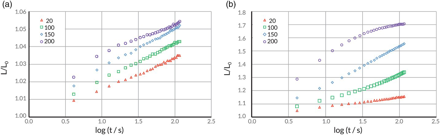
For hard-doped PZT, the logarithmic model gives good results at room temperature where a rate of 7.5% per decade can be identified (refer to Fig. 5b). At 100–150°C, the creep rate increases with time by up to 30% per decade. At 200°C, creep starts at a high rate then levels out to under 10% per decade. A similar behaviour has been observed during initial poling process 10 with the difference that the main parameter in the study was the poling field rather than the temperature. However, in the present case, the samples are fully poled at the start of the test. This was even confirmed by reproducing the test using the same samples, leading to identical results. It appears that the elevated temperature enables the generation of additional poling in the material through a slow process. This additional poling is however reversible and disappears over time at zero field.
This effect could be a concern for positioning application that typically employ very-low-frequency signals and require stable position over time.
Conclusions
Mechanical and electrical designers generally have limited knowledge about piezoelectric devices. There is a need for a simple description of the main properties of PZT actuators from a practical point of view, in order to allow the integration of PZT actuator in more complex systems, for example, in the field of aeronautics. Furthermore, this characterisation must take into account temperature which is the main parameter influencing performance.
A set of essential characteristics have been defined: allowable reverse field, apparent capacitance, apparent dielectric losses, free stroke, blocking force and height. Secondary parameters such as creep are also considered. In order to release the requirements on test equipment, a four-step measurement sequence is presented. Two of these steps, the measurement of dielectric properties and of thermal expansion, are presented in more detail here.
Test results on soft-doped PZT indicate that dielectric losses decrease above 1.5 kV mm−1. This effect is even more pronounced at a high temperature; for example, at 200°C, dielectric losses peak at 0.75 kV mm−1. The interpretation is that the material has a less hysteretic behaviour at a high field and at a high temperature, so the losses decrease in proportion. On the other hand for hard-doped PZT, a peak cannot be seen in the tested range up to 3 kV mm−1. Furthermore, the increasing trend is accelerating with the temperature. As a result, although hard-doped PZT maintains an advantage in terms of power dissipation for high-frequency applications, the choice between hard- and soft-doped materials is challenged at a high temperature.
Creep measurements on soft-doped PZT follow the traditional logarithmic model at elevated temperatures. Also, the creep rate was found to be relatively stable at approximately 2% per decade. Hard-doped PZT has a more complex behaviour. Although it follows the logarithmic model at room temperature, at an elevated temperature, the creep rate increases over time. This phenomenon has been observed previously during the initial poling process. The suggested explanation is that some additional poling with high activation energy is achieved in the material. However, this poling is reversible.
Footnotes
Acknowledgements
The research leading to these results has received funding from the European Union's Seventh Framework Programme (FP7/2007–2013) for the Clean Sky Joint Technology Initiative under grant agreement no. 632604.